 EN
 IT Italiano
 ES Español
 FR Français
 DE Deutsch
Description
Technical Description
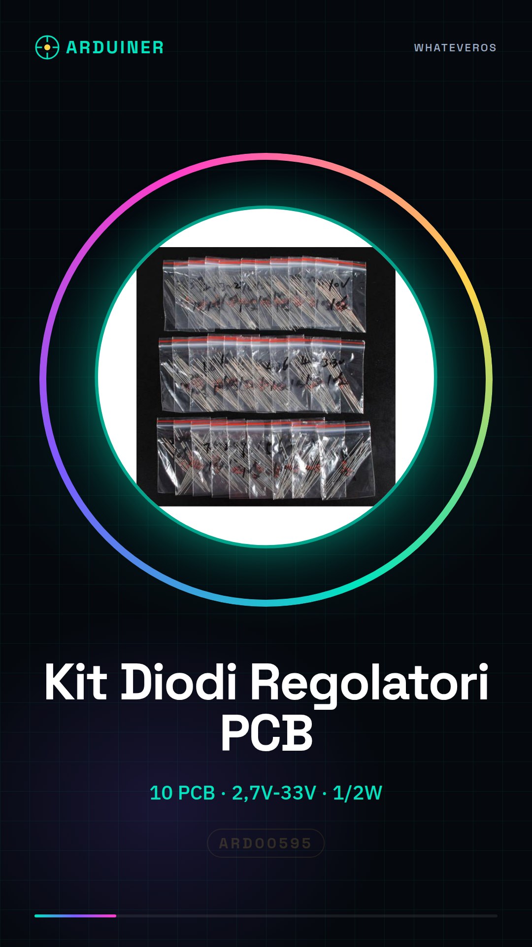
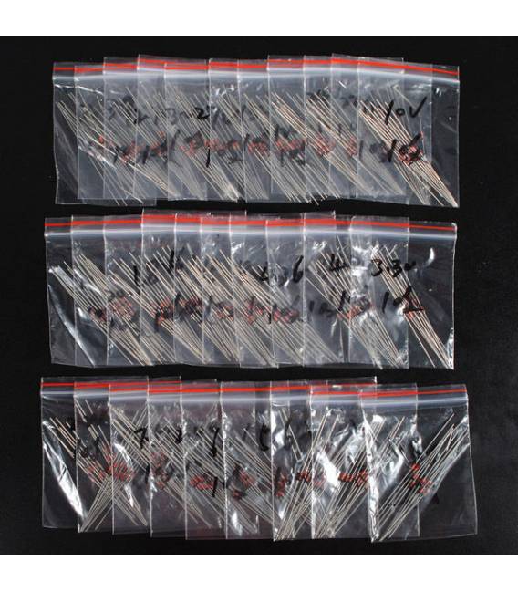
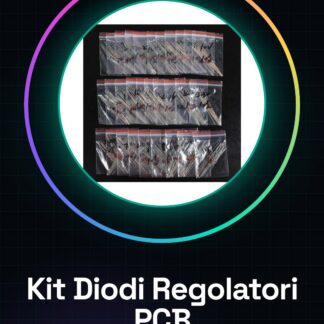
The Regulator Diodes PCB Kit 1/2W includes 10 printed circuit boards with 23 voltage regulation values ranging from 2.7V to 33V. These circuits are designed to regulate electrical voltage in various electronic projects, providing a flexible solution for managing output voltage.
Each printed circuit board in the kit includes a regulator diode that allows for establishing a constant output voltage regardless of fluctuations in the supply voltage. These components are useful for projects that require a stable and adjustable voltage.
The kit is suitable for applications requiring regulated and stable power supply, such as prototypes and laboratory projects.
Key Specifications
| Parameter | Value |
| Model | Regulator Diodes PCB Kit 1/2W |
| Quantity | 10 pieces |
| Voltage Values | 23 values from 2.7V to 33V |
| Power | 1/2W |
| Dimensions | N/D (see manufacturer’s datasheet) |
| Interface | VCC and GND pins |
| Container | N/D (see manufacturer’s datasheet) |
Installation and Usage
- Install the PCB on your circuit.
- Connect the power input to the VCC pin of the PCB.
- Connect the ground (GND) between Arduino and PCB.
- Select the desired output value from the datasheet.
- Verify that the output voltage is stable with a multimeter.
Compatibility and Requirements
- The kit is compatible with Arduino Uno and other microcontrollers.
- A multimeter is required for voltage verification.
- A JST connector is required for connection.
- A connection cable is required for connecting the PCB to the microcontroller.
Limitations and Important Notes
- Does not provide power for high-power devices.
- Requires proper selection of output value.
- Requires proper power supply to function correctly.
- Not designed for high-frequency applications.
Troubleshooting
Output voltage is unstable.
Possible cause: Incorrect connection between VCC and GND.
Solution: Check and correct the connection between VCC and GND.
Output voltage does not reach the desired value.
Possible cause: Output value not selected correctly.
Solution: Select the desired output value from the datasheet.
The PCB does not respond.
Possible cause: Insufficient or excessive power supply.
Solution: Check that the power supply is correct and sufficient.
The PCB produces excessive heat.
Possible cause: Excessive power supply or excessive load.
Solution: Check that the power supply and load are adequate.
Use cases
Voltage regulator for RGB LED power supply
Objective: Regulate voltage to power RGB LEDs.
What’s needed: Voltage Regulator Diodes Kit PCB 1/2W, Arduino Uno, RGB LEDs, Multimeter.
Steps: 1) Install the PCB on the circuit. 2) Connect the power input to the VCC pin of the PCB. 3) Connect the ground (GND) between Arduino and PCB. 4) Select the desired output value from the datasheet. 5) Verify that the output voltage is stable with a multimeter.
Expected result: The RGB LED is powered with a stable voltage.
Voltage Regulator for Sensor Power Supply
Objective: Regulate voltage to power sensors.
What’s needed: Voltage Regulator Diodes Kit PCB 1/2W, Arduino Uno, Sensors, Multimeter.
Steps: 1) Install the PCB on the circuit. 2) Connect the power input to the VCC pin of the PCB. 3) Connect the ground (GND) between Arduino and PCB. 4) Select the desired output value from the datasheet. 5) Verify that the output voltage is stable with a multimeter.
Expected result: The sensors are powered with a stable voltage.
Voltage regulator for relay power supply
Objective: Regulate the voltage to power the relay.
What is needed: Kit Regulator Diodes PCB 1/2W, Arduino Uno, Relay, Multimeter.
Steps: 1) Install the PCB on the circuit. 2) Connect the power input to the VCC pin of the PCB. 3) Connect the ground (GND) between Arduino and PCB. 4) Select the desired output value from the datasheet. 5) Verify that the output voltage is stable with a multimeter.
Expected result: The relay is powered with a stable voltage.
Voltage Regulator for Motor Power Supply
Objective: Regulate the voltage to power motors.
What’s needed: Kit of Regulator Diodes PCB 1/2W, Arduino Uno, Motors, Multimeter.
Steps: 1) Install the PCB on the circuit. 2) Connect the power input to the VCC pin of the PCB. 3) Connect the ground (GND) between Arduino and PCB. 4) Select the desired output value from the datasheet. 5) Verify that the output voltage is stable with a multimeter.
Expected Result: The motors are powered with a stable voltage.
Voltage Regulator for LCD Display Power Supply
Objective: Regulate the voltage to power LCD displays.
What’s needed: Kit of Regulator Diodes PCB 1/2W, Arduino Uno, LCD Display, Multimeter.
Steps: 1) Install the PCB on the circuit. 2) Connect the power input to the VCC pin of the PCB. 3) Connect the ground (GND) between Arduino and PCB. 4) Select the desired output value from the datasheet. 5) Verify that the output voltage is stable with a multimeter.
Expected result: The LCD display is powered with a stable voltage.
Voltage regulator for low voltage relay power supply
Objective: Regulate the voltage to power low voltage relays.
What you need: Kit of 1/2W Regulator Diodes PCB, Arduino Uno, Low Voltage Relay, Multimeter.
Steps: 1) Install the PCB on the circuit. 2) Connect the power input to the VCC pin of the PCB. 3) Connect the ground (GND) between Arduino and PCB. 4) Select the desired output value from the datasheet. 5) Verify that the output voltage is stable with a multimeter.
Expected result: The low voltage relay is powered with a stable voltage.
Voltage regulator for temperature sensor power supply
Objective: To regulate the voltage to power temperature sensors.
What you need: Kit of Regulator Diodes PCB 1/2W, Arduino Uno, Temperature Sensors, Multimeter.
Steps: 1) Install the PCB on the circuit. 2) Connect the power input to the VCC pin of the PCB. 3) Connect the ground (GND) between Arduino and PCB. 4) Select the desired output value from the datasheet. 5) Verify that the output voltage is stable with a multimeter.
Expected result: The temperature sensors are powered with a stable voltage.
Voltage regulator for LED display power supply
Objective: To regulate the voltage to power LED displays.
What you need: Kit of Regulator Diodes PCB 1/2W, Arduino Uno, LED Display, Multimeter.
Steps: 1) Install the PCB on the circuit. 2) Connect the power input to the VCC pin of the PCB. 3) Connect the ground (GND) between Arduino and PCB. 4) Select the desired output value from the datasheet. 5) Verify that the output voltage is stable with a multimeter.
Expected result: The LED display is powered with a stable voltage.
In the package
- 10 pieces of Regulator Diode Kit PCB 1/2W for 23 values from 2.7V to 33V
Complete the project
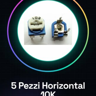
- Kit Adjustable Potentiometers PCB Breadboard 3296W 5 Pieces for 9 Values: 200R, 500R, 1K, 2K, 5K, 10K, 25K, 100K, 200K: Used to regulate the power supply voltage in various electronic projects.
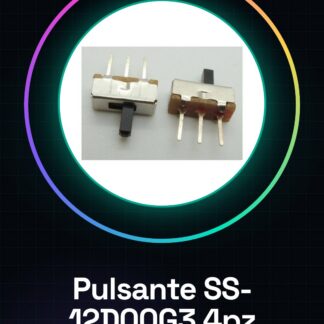
- 4 Pieces SS-12D00G3 2 positions SPDT 1P2T Panel for PCB vertical 3 pin Switch for breadboard: Used for the connection between the PCB and the microcontroller.
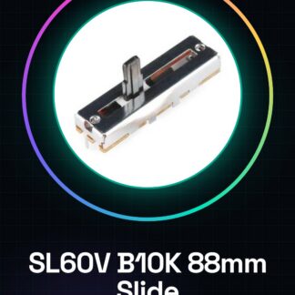
- Linear potentiometer single turn B 50K with Zigrinato shaft 20mm for Arduino Breadboard PCB: Used for output voltage verification.
Technical FAQ
What is the maximum power?
Check the datasheet.
Can I use these PCBs with other microcontrollers?
Yes, just connect them correctly to VCC and GND.
Why is the output voltage not stable?
Incorrect connection between VCC and GND. Check and correct the connection.
Why does the output voltage not reach the desired value?
Output value not correctly selected. Select the desired output value from the datasheet.
Tutorial: How to use the Voltage Regulator PCB Kit
Kit of 10 pieces for regulating electrical voltage. Ideal for Arduino projects and prototypes.
What you need
- Arduino Uno
- JST Connectors
- Connection Cables
Steps
- Install the PCB on your own circuit.
- Connect the power input to the VCC pin of the PCB.
- Connect the ground (GND) between Arduino and PCB.
- Select the desired output value from the datasheet.
- Check that the output voltage is stable with a multimeter.
Mini project
Voltage regulator for RGB LED power supply.
Common mistakes
- Incorrect connection between VCC and GND
- Output value not selected correctly.
- Insufficient or excessive power supply.
Recommended accessories
- Arduino Uno
- RGB LED
- Multimeter
Frequently asked questions
What is the maximum power?
Check the datasheet.
Can I use these PCBs with other microcontrollers?
Yes, just connect them correctly to VCC and GND.
Reviews
There are no reviews yet.