 EN
 IT Italiano
 ES Español
 FR Français
 DE Deutsch
Description
Technical Specifications
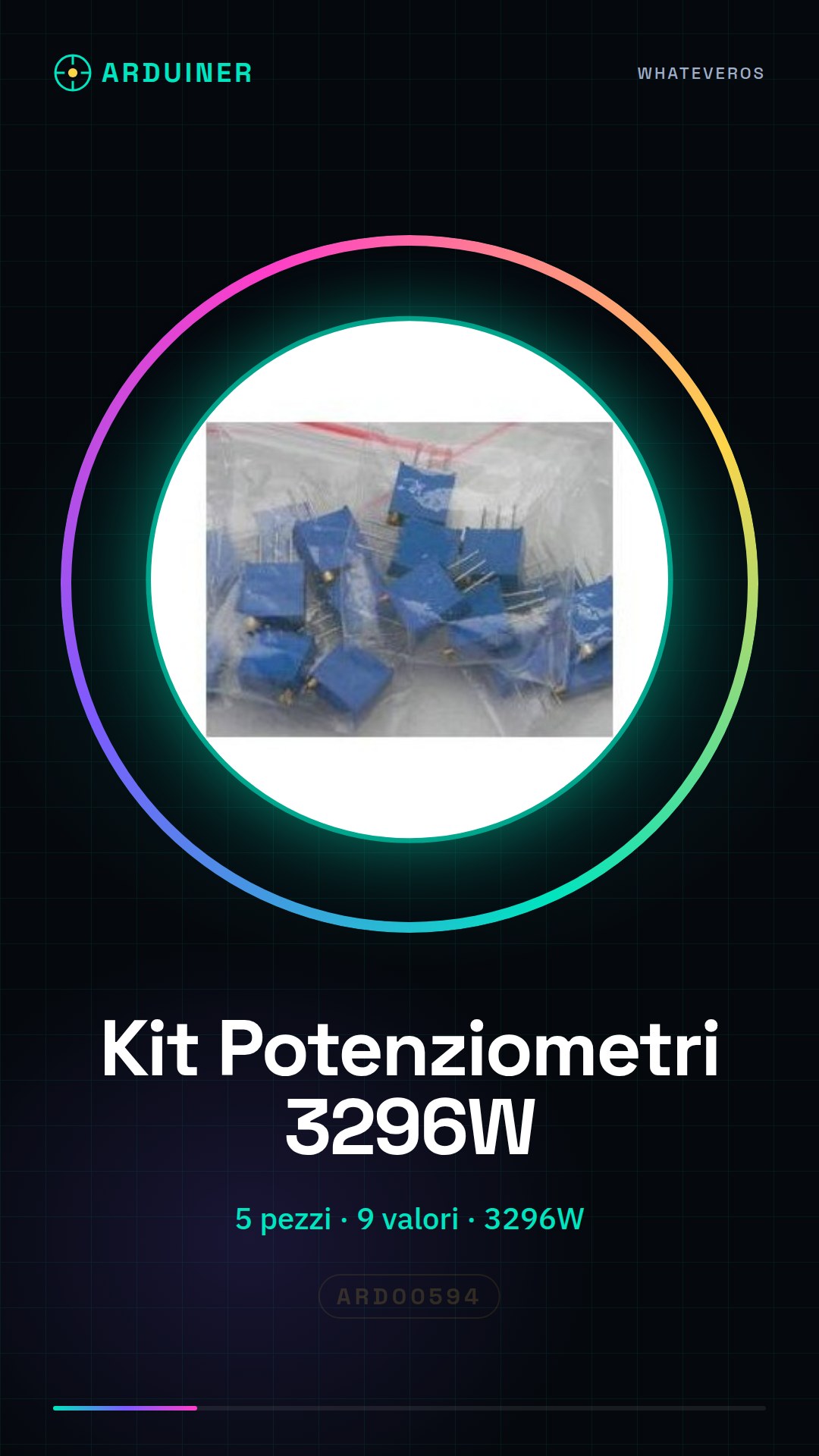
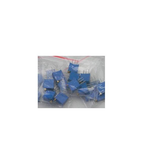
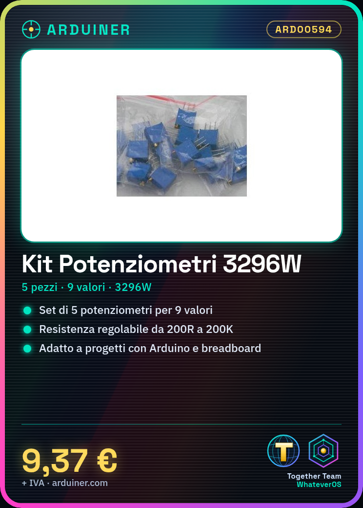
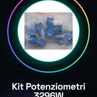
The Adjustable Potentiometer PCB Breadboard Kit 3296W includes five potentiometers with nine different resistance values. These potentiometers are designed to be used on a breadboard and are suitable for electronic projects and Arduino prototypes. Each potentiometer has a variable resistance that can be manually adjusted, allowing control over the flow of electrical current in a circuit.
The potentiometers in the kit can be used to vary the voltage level in a circuit, for example to adjust the volume of an audio amplifier or to control the brightness of a lamp. Their application is widely varied, from controlling electronic devices to testing and calibrating circuits.
To install these potentiometers, it is necessary to connect them to a breadboard and a microcontroller such as Arduino. The variable resistance can be read by the microcontroller through an analog interface, allowing the read values to be used to control other devices or to perform calculations and tests.
Key Specifications
| Parameter | Value |
| Model | 3296W |
| Quantity | 5 pieces |
| Resistance Values | 200R, 500R, 1K, 2K, 5K, 10K, 25K, 100K, 200K |
| Interface | Breadboard |
| Dimensions | N/D (see manufacturer’s datasheet) |
| Container | N/D (see manufacturer’s datasheet) |
Installation and Usage
- Install the kit on a breadboard.
- Connect the potentiometers to the Arduino using jumper cables.
- Check the datasheet for the desired resistance value for each potentiometer.
- Write an Arduino sketch to read the values from potentiometers.
- Use the serial monitor to display the data read from the potentiometers.
Compatibility and Requirements
- The kit is compatible with Arduino and other microcontrollers with analog interface.
- A breadboard is required for installation.
- Jumper cables are required for connections.
- A datasheet is needed to verify resistance values.
Limitations and Important Notes
- Potentiometers cannot be used as fixed resistors.
- It is necessary to check the correct resistance value on the datasheet before using the potentiometers.
- The kit does not include a datasheet, but it is available upon request.
- Make sure to connect the potentiometers correctly to avoid damage.
Troubleshooting
The values read from the potentiometers are incorrect.
Probable cause: The potentiometers are incorrectly connected.
Solution: Check connections and correct resistance value on the datasheet.
Potentiometers do not change resistance value.
Probable cause: Potentiometers are stuck or damaged.
Solution: Physically check potentiometers to ensure they can move freely.
The serial monitor does not display data read from potentiometers.
Probable cause: The Arduino code is incorrect.
Solution: Check the code and ensure it is correctly written to read values from potentiometers.
The kit does not contain a datasheet.
Probable cause: The datasheet is not included in the kit.
Solution: Request the datasheet from the supplier or the manufacturer’s website.
Use cases
Light sensor
Objective: Adjust the brightness of a lamp.
What is needed: Potentiometer kit, Arduino, breadboard, jumper wires, lamp.
Steps: 1) Install potentiometers on the breadboard. 2) Connect the potentiometers to the Arduino. 3) Write an Arduino sketch that reads the values of the potentiometers. 4) Use the read values to adjust the brightness of the lamp.
Expected result: The brightness of the lamp can be manually adjusted using the potentiometers.
Volume Control
Objective: Adjust the volume of an amplifier.
What you need: Potentiometer kit, Arduino, breadboard, jumper cables, amplifier.
Steps: 1) Install potentiometers on the breadboard. 2) Connect the potentiometers to the Arduino. 3) Write an Arduino sketch that reads the values of the potentiometers. 4) Use the read values to adjust the volume of the amplifier.
Expected result: The volume of the amplifier can be manually adjusted using the potentiometers.
LED Dimmer
Objective: Adjust the intensity of an LED.
Required: Potentiometer kit, Arduino, breadboard, jumper wires, LED.
Steps: 1) Install the potentiometers on the breadboard. 2) Connect the potentiometers to the Arduino. 3) Write an Arduino sketch that reads the values of the potentiometers. 4) Use the read values to adjust the LED brightness.
Expected result: The LED brightness can be manually adjusted using the potentiometers.
Temperature Regulator
Objective: Regulate the temperature of a system.
Required: Potentiometer kit, Arduino, breadboard, jumper wires, temperature sensor.
Steps: 1) Install the potentiometers on the breadboard. 2) Connect the potentiometers to the Arduino. 3) Write an Arduino sketch that reads the values of the potentiometers. 4) Use the read values to adjust the system temperature.
Expected result: The system temperature can be manually adjusted using the potentiometers.
Brightness Regulator
Objective: Adjust the brightness of a screen.
What you need: Potentiometer kit, Arduino, breadboard, jumper wires, LCD screen.
Steps: 1) Install the potentiometers on the breadboard. 2) Connect the potentiometers to the Arduino. 3) Write an Arduino sketch that reads the values of the potentiometers. 4) Use the read values to adjust the brightness of the screen.
Expected result: The brightness of the screen can be manually adjusted using the potentiometers.
Speed Regulator
Objective: Adjust the speed of a motor.
What you need: Potentiometer kit, Arduino, breadboard, jumper wires, motor.
Steps: 1) Install the potentiometers on the breadboard. 2) Connect the potentiometers to the Arduino. 3) Write an Arduino sketch that reads the values of the potentiometers. 4) Use the read values to adjust the speed of the motor.
Expected result: The motor speed can be manually adjusted using the potentiometers.
Voltage Regulator
Objective: Regulate the voltage of a circuit.
What’s needed: Potentiometer kit, Arduino, breadboard, jumper cables, circuit.
Steps: 1) Install the potentiometers on the breadboard. 2) Connect the potentiometers to the Arduino. 3) Write an Arduino sketch that reads the values of the potentiometers. 4) Use the read values to regulate the voltage of the circuit.
Expected result: The voltage of the circuit can be manually adjusted using the potentiometers.
Headphone Volume Regulator
Objective: Regulate the volume of headphones.
What’s needed: Potentiometer kit, Arduino, breadboard, jumper cables, headphones.
Steps: 1) Install potentiometers on the breadboard. 2) Connect potentiometers to the Arduino. 3) Write an Arduino sketch that reads the values of the potentiometers. 4) Use the read values to adjust the volume of the headphones.
Expected result: The volume of the headphones can be manually adjusted using the potentiometers.
In the package
- 5 pieces
Complete the project
- 4 Pieces SS-12D00G3 2 positions SPDT 1P2T Vertical PCB panel 3 pin Push button for breadboard: Used to connect the potentiometers to the breadboard.
Technical FAQs
What are the resistance values in the kit?
The kit contains potentiometers with resistance values of 200R, 500R, 1K, 2K, 5K, 10K, 25K, 100K, 200K.
How to connect potentiometers to the breadboard?
Each pin of the potentiometer must be connected to the breadboard using jumper wires.
Why are the values read from the potentiometers incorrect?
The potentiometers may be incorrectly connected or the resistance may be wrong.
Why does the serial monitor not show the data read from the potentiometers?
The Arduino code may be incorrect or the potentiometers may be incorrectly connected.
Tutorial: How to use Potentiometer PCB Kit Breadboard
Adjustable potentiometer PCB kit for Arduino and electronic projects. For beginners and makers.
What you need
- Arduino
- Breadboard
- Jumper wires
Steps
- Install the kit on a breadboard
- Connect the potentiometers to the Arduino using jumper wires
- Check the datasheet for the desired resistance value for each potentiometer
- Write an Arduino sketch that reads the values of the potentiometers
- Use the serial monitor to display the data read from the potentiometers
Example code
void setup() {
  Serial.begin(9600);
}

void loop() {
  int sensorValue = analogRead(A0);
  Serial.println(sensorValue);
}
Mini project
Build an LED dimmer using one of the potentiometers
Common mistakes
- Connect the potentiometers to the breadboard incorrectly
- Do not verify resistance value on datasheet
- Write code without first testing with serial monitor
Recommended accessories
- RGB LED Kit for Arduino
- Large breadboard
- Set of colored jumper wires
- Arduino Uno R3
Frequently asked questions
What resistance values does the kit have?
200R, 500R, 1K, 2K, 5K, 10K, 25K, 100K, 200K
How to connect potentiometers to the breadboard?
Each pin of the potentiometer must be connected to a bus on the breadboard

Reviews
There are no reviews yet.