 EN
 IT Italiano
 ES Español
 FR Français
 DE Deutsch
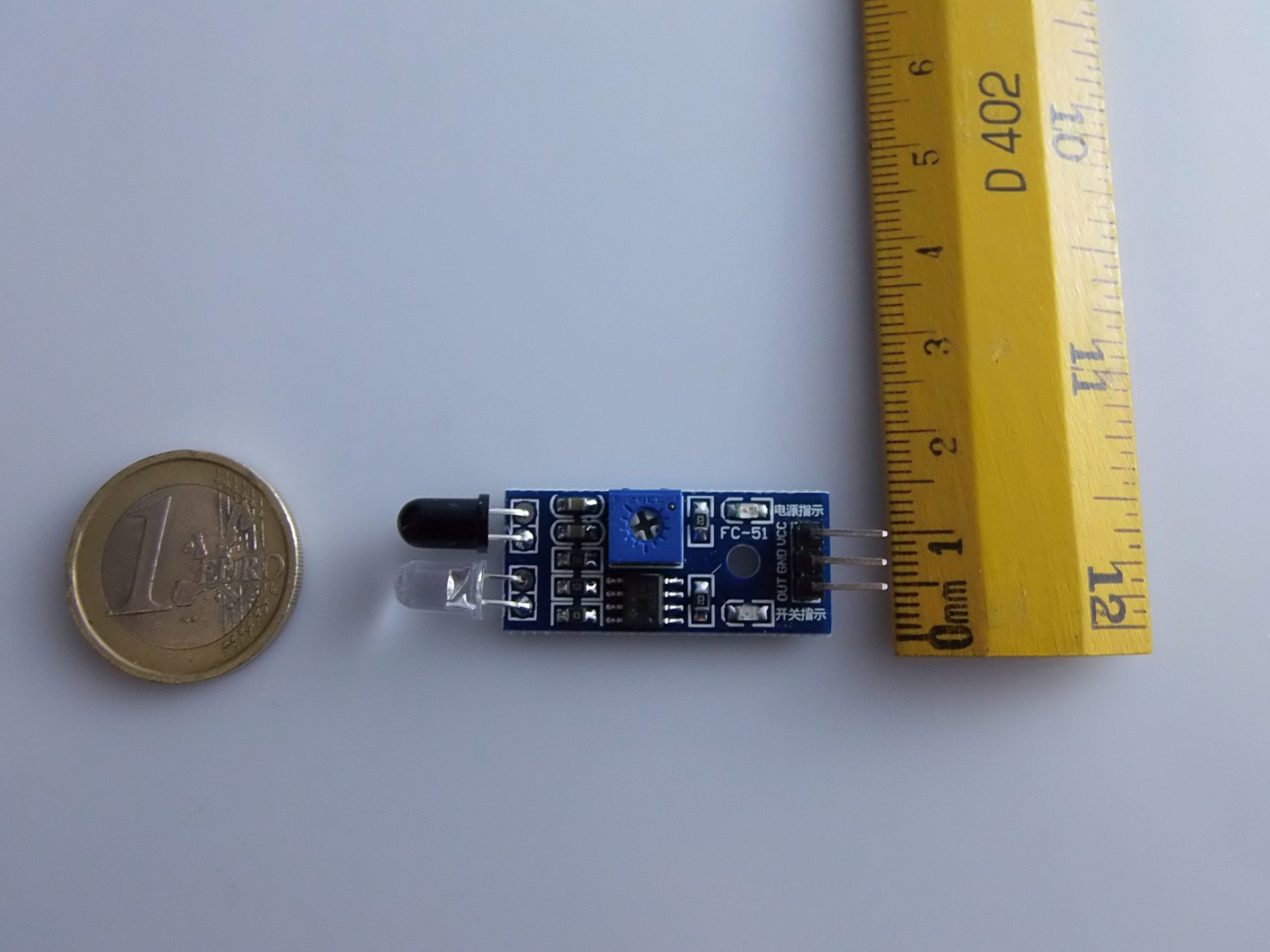
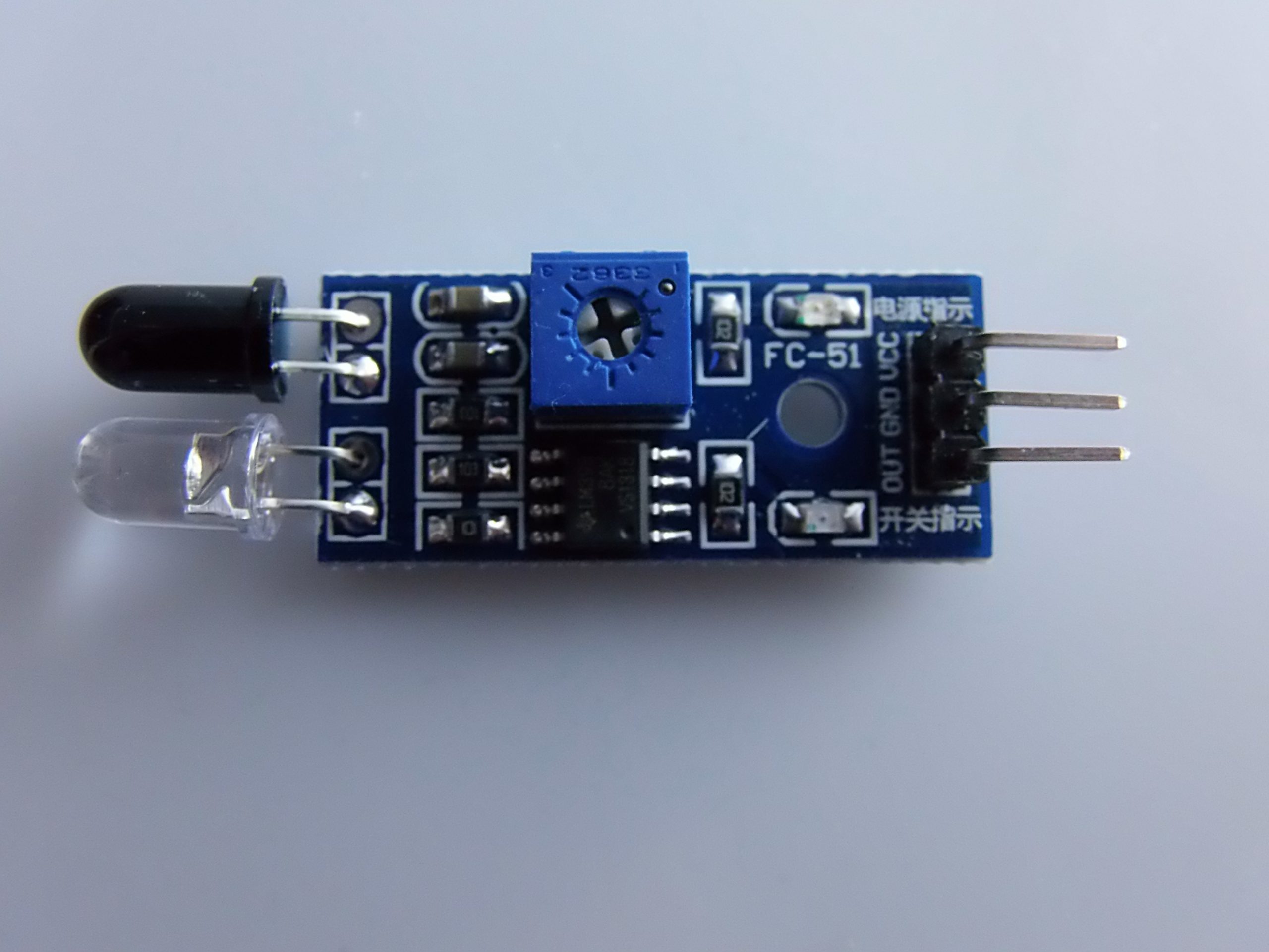
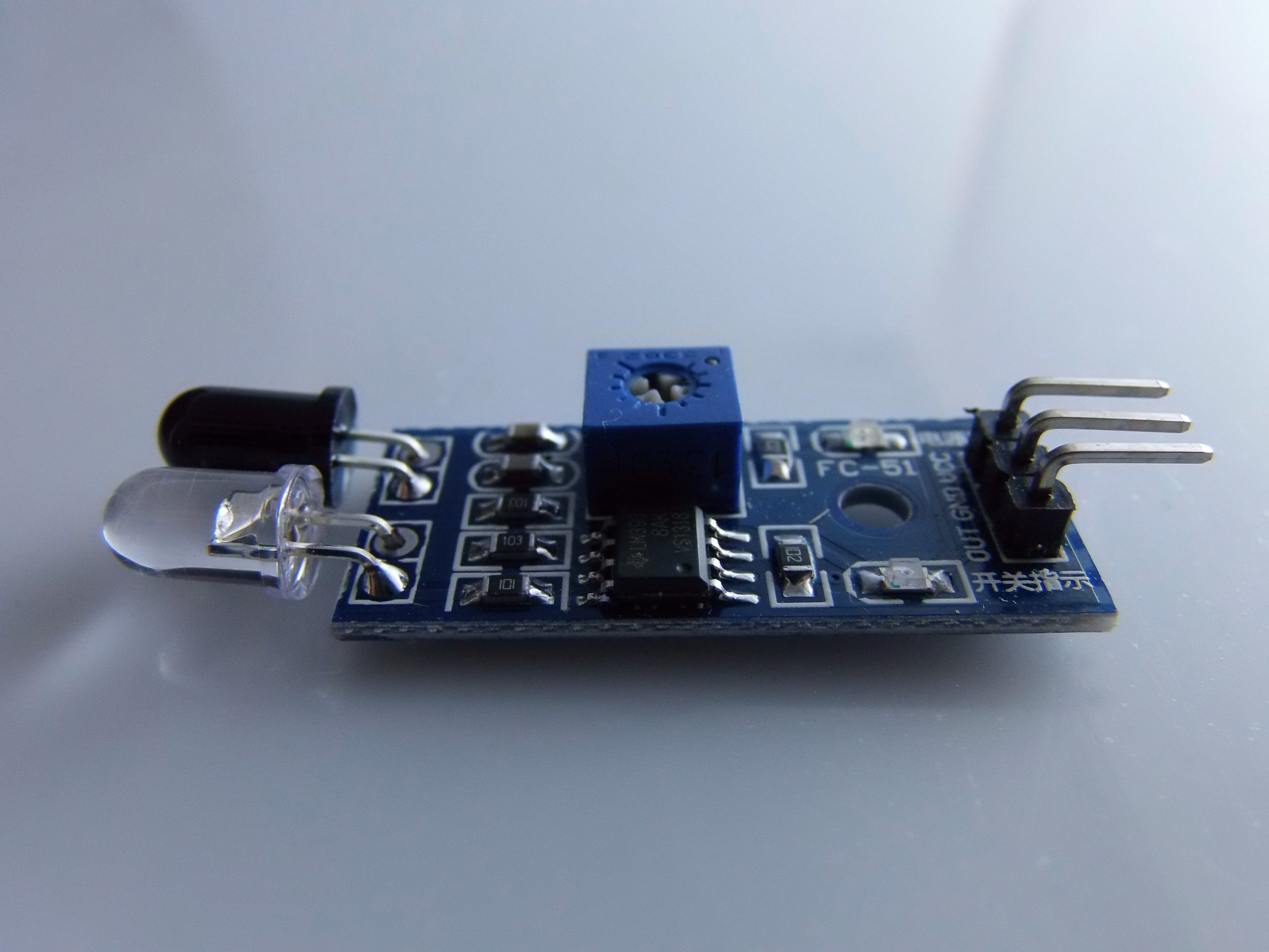
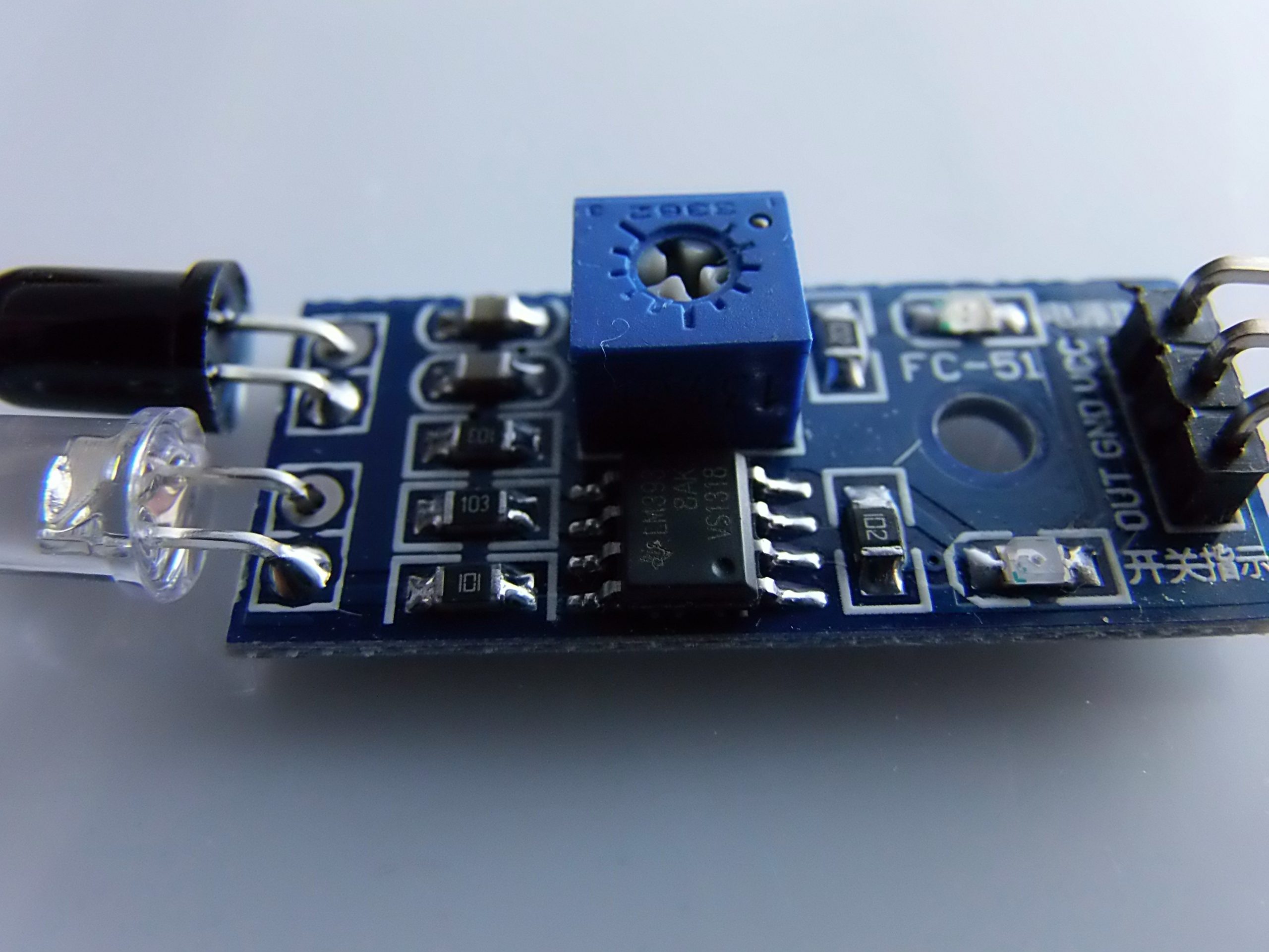
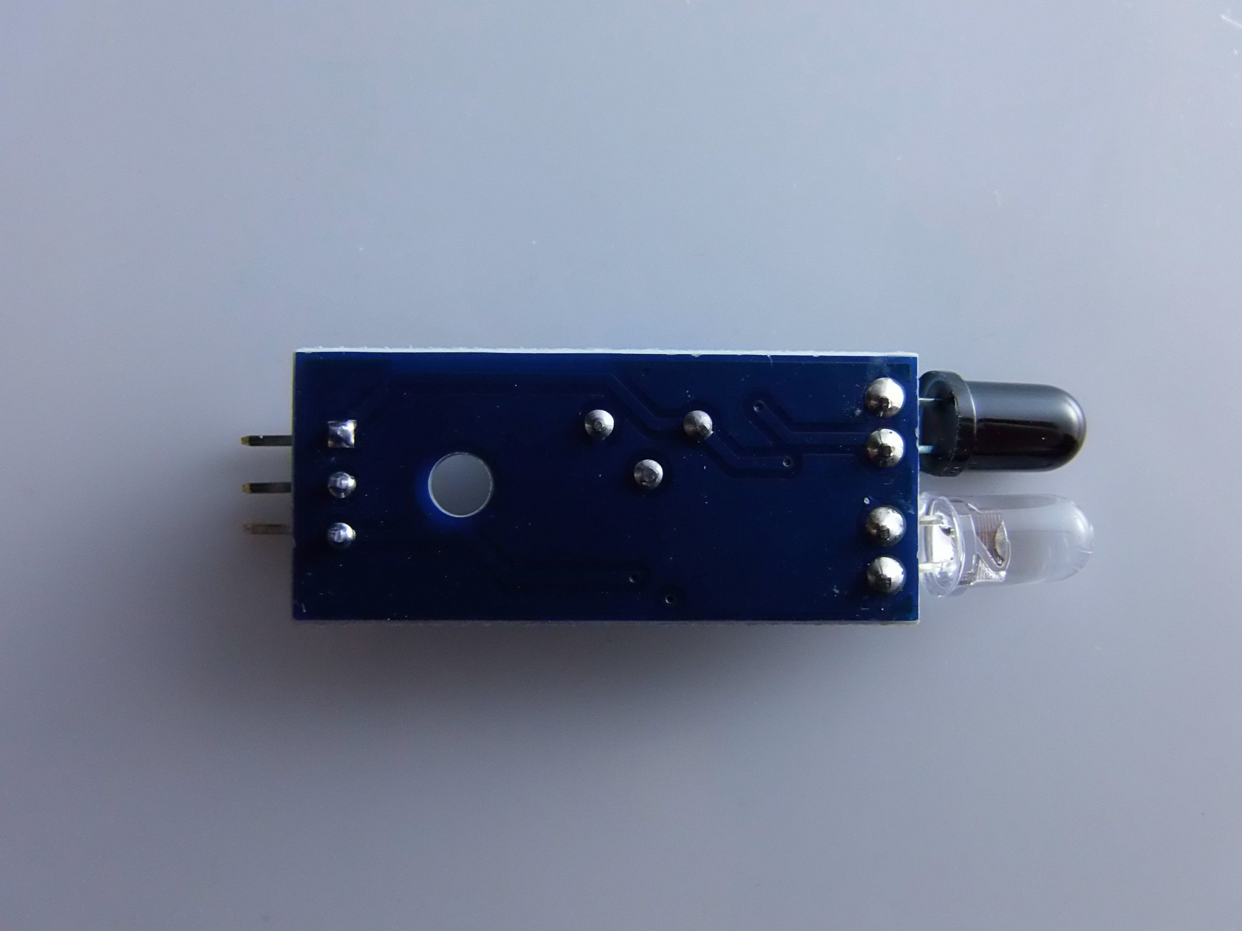
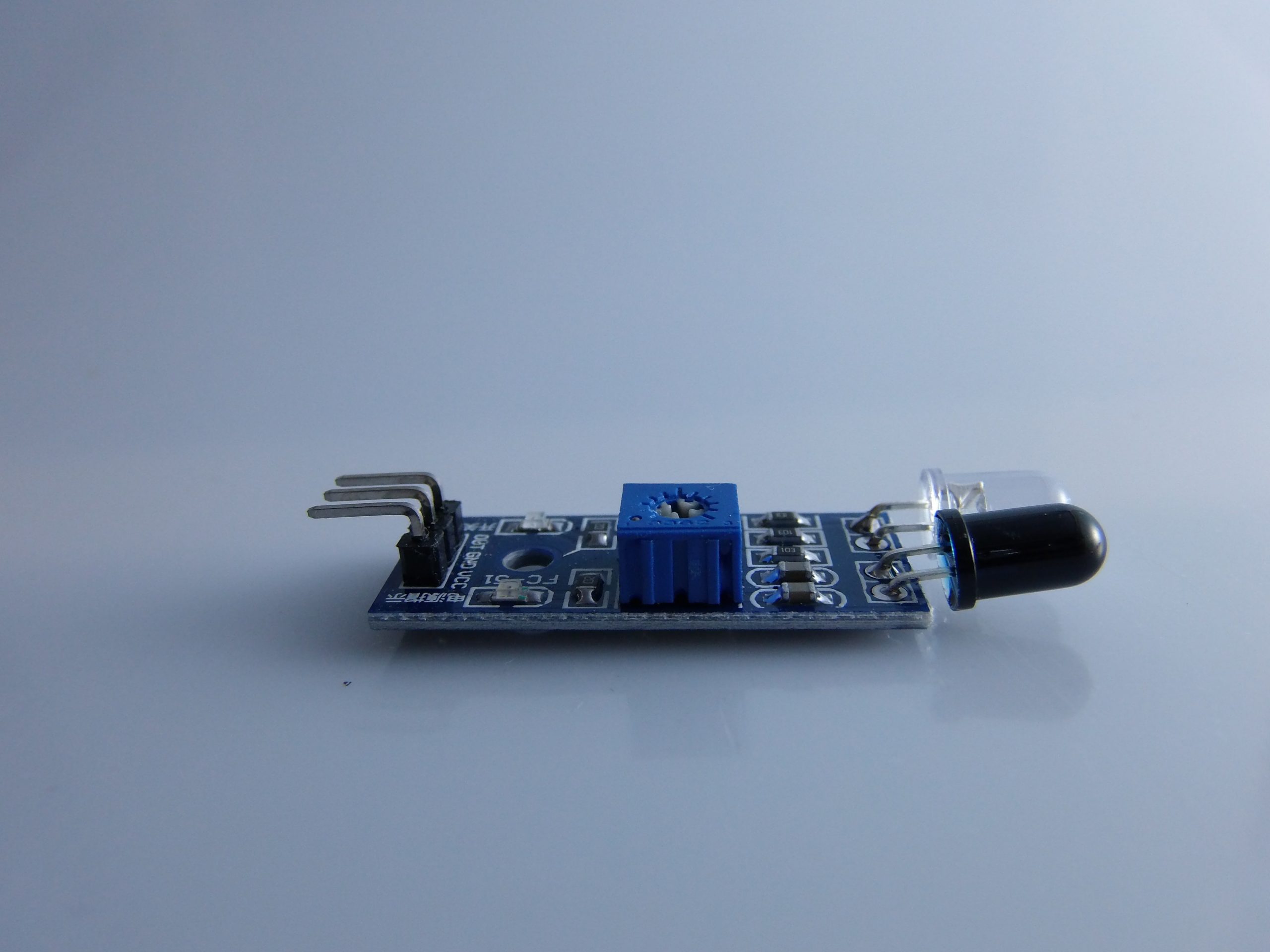
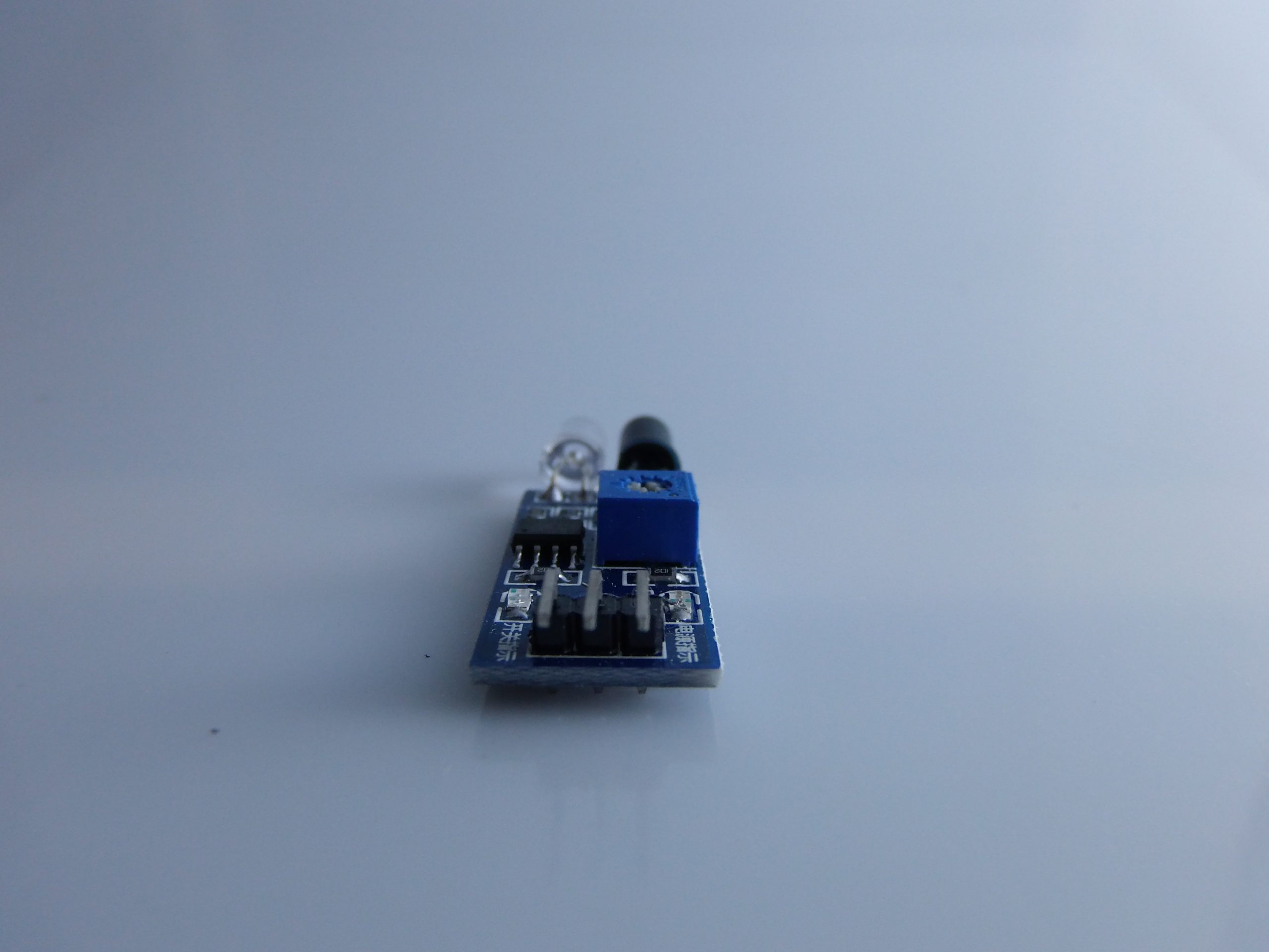
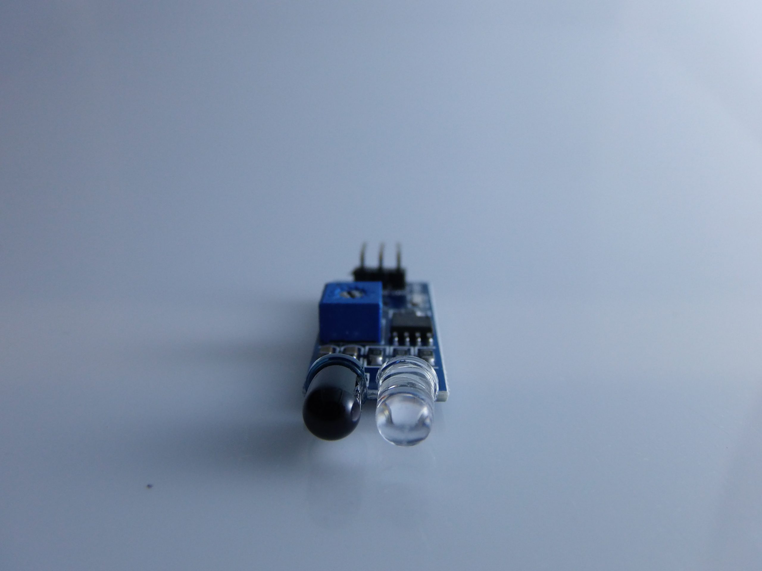
Description
🚗 Infrared Obstacle Avoidance Sensor Module – Complete Description
✅ What is it?
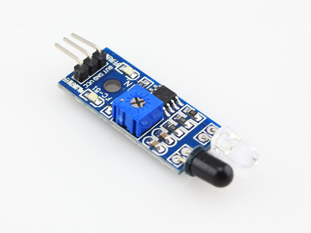
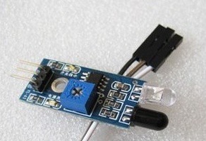
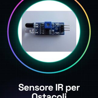
The Infrared Obstacle Avoidance Module is an infrared sensor that detects the presence of objects or obstacles in front of it, based on the reflection of infrared light. It is commonly used in mobile robots, autonomous vehicles, counting devices, and generally in projects that require object detection without physical contact.
🔍 Technical Specifications
| Specification | Value |
|---|---|
| Operating Voltage | 3.3V – 5V DC |
| Detection Range | 2 – 30 cm (adjustable) |
| Output Type | Digital (HIGH/LOW) |
| Detection Angle | Approximately 35° |
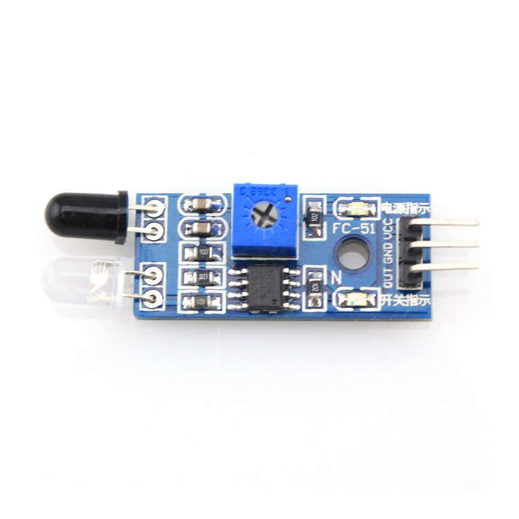
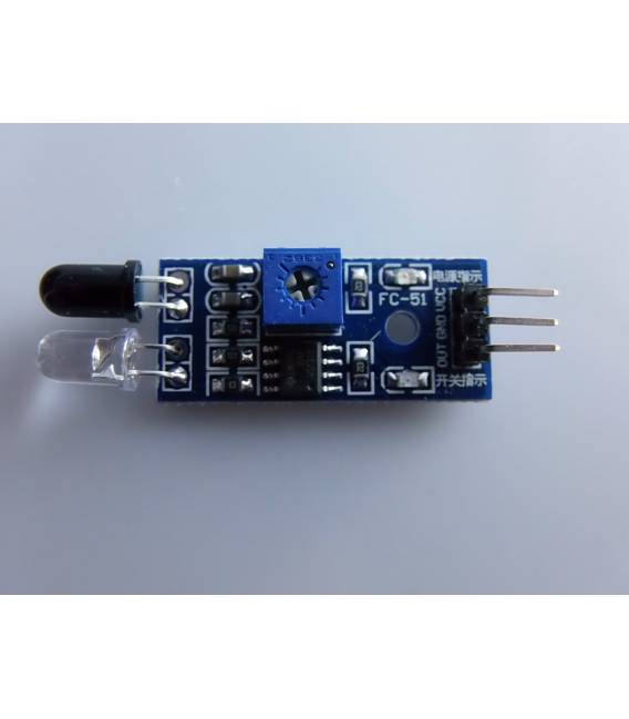
| Main Components | IR LED emitter + receiver, LM393 comparator |
| LED Indicators | Power LED + Detection LED |
| Interface | 3 pin: VCC, GND, OUT |
| Sensitivity Adjustment | Trimmer (blue screw) |
Works by detecting reflected IR light: a nearby object reflects the emitted IR signal and is detected.
🔌 Connecting to your Arduino
🧰 Required materials:
- Arduino Uno/Nano/Mega
- IR obstacle avoidance sensor module
- Jumper wires
- Breadboard (optional)
📌 Connection diagram
| Pin IR module | Arduino connection |
|---|---|
| VCC | 5V |
| GND | GND |
| OUT | D2 (or any digital pin) |
The OUT pin provides a digital signal:
LOWwhen an obstacle is detected.
👨💻 Basic example code
🧪 Objective: turn on an LED on Arduino when an obstacle is detected.
#define SENSOR_PIN 2 // OUT del sensore
#define LED_PIN 13 // LED integrato sull'Arduino

void setup() {
 pinMode(SENSOR_PIN, INPUT);
 pinMode(LED_PIN, OUTPUT);
 Serial.begin(9600);
}

void loop() {
 int statoSensore = digitalRead(SENSOR_PIN);

 if (statoSensore == LOW) {
 // Ostacolo rilevato
 Serial.println("🚧 Ostacolo rilevato!");
 digitalWrite(LED_PIN, HIGH);
 } else {
 // Nessun ostacolo
 digitalWrite(LED_PIN, LOW);
 }

 delay(100);
}
Note: Generally the sensor returns
LOWwhen there is an object in front. Always check with the serial monitor.
💡 Advanced example: Robot obstacle avoidance (with 2 sensors)
Using two IR sensors to decide the direction of movement.
#define LEFT_SENSOR_PIN 2
#define RIGHT_SENSOR_PIN 3
#define LEFT_MOTOR 8
#define RIGHT_MOTOR 9

void setup() {
 pinMode(LEFT_SENSOR_PIN, INPUT);
 pinMode(RIGHT_SENSOR_PIN, INPUT);
 pinMode(LEFT_MOTOR, OUTPUT);
 pinMode(RIGHT_MOTOR, OUTPUT);
}

void loop() {
 int leftObstacle = digitalRead(LEFT_SENSOR_PIN);
 int rightObstacle = digitalRead(RIGHT_SENSOR_PIN);

 if (leftObstacle == LOW && rightObstacle == LOW) {
 // Ostacolo davanti → fermati
 digitalWrite(LEFT_MOTOR, LOW);
 digitalWrite(RIGHT_MOTOR, LOW);
 } else if (leftObstacle == LOW) {
 // Ostacolo a sinistra → gira a destra
 digitalWrite(LEFT_MOTOR, HIGH);
 digitalWrite(RIGHT_MOTOR, LOW);
 } else if (rightObstacle == LOW) {
 // Ostacolo a destra → gira a sinistra
 digitalWrite(LEFT_MOTOR, LOW);
 digitalWrite(RIGHT_MOTOR, HIGH);
 } else {
 // Nessun ostacolo → vai avanti
 digitalWrite(LEFT_MOTOR, HIGH);
 digitalWrite(RIGHT_MOTOR, HIGH);
 }

 delay(100);
}
In a real robot,
LEFT_MOTOReRIGHT_MOTORshould be connected to a motor driver (e.g., L298N or L9110S).
⚙️ Practical Tips
- 🔧 Sensitivity Adjustment: turn the trimmer on the module to increase or decrease the detection range.
- 🌞 Environmental Conditions: direct sunlight can interfere with the IR sensor. Use it in indoor or controlled environments.
- 🔋 Voltage: works well with both 3.3V and 5V, but 5V is recommended for maximum reliability.
🧠 Possible Applications
- Autonomous Mobile Robots
- Object Counters on Conveyor Belts
- Proximity or Presence Sensors
- Games and Interactive Interfaces
- Simple Automation (e.g., automatic opening)
📦 Feature Summary
- ✔️ Object Detection contactless
- ✔️ Easy to Integrate With Arduino
- ✔️ Affordable and adjustable
- ✔️ Digital output, easy to read
- ✔️ Suitable for educational and hobby projects
Perfect! Below is a educational presentation divided into slides textual, suitable for PowerPoint, Google Slides, Canva or any other presentation tool.
📊 Presentation: Infrared Obstacle Avoidance Sensor with Arduino
🔹 Slide 1: Title
Infrared Sensor for Obstacle Avoidance
Introduction and use with Arduino
👨🏫 Course: Introduction to Robotics
📅 Date: [inserire data]
📍 By: [nome docente/studente]
🔹 Slide 2: What is the infrared obstacle avoidance sensor?
- Sensor that detect objects without contact via infrared
- Use reflected IR light to detect distance from an obstacle
- Output digital: HIGH = no obstacle, LOW = obstacle present
- Ideal for mobile robots, automation, alarm systems
🔹 Slide 3: Main components of the module
- IR LED emitter
- IR Photodiode receiver
- LM393 Comparator for logic management
- Status LED (Power + Detection)
- Trimmer for adjust sensitivity
- 3 Pin: VCC, GND, OUT
🔹 Slide 4: Technical Specifications
| Characteristic | Value |
|---|---|
| Voltage | 3.3V – 5V |
| Operational Range | 2 – 30 cm (adjustable) |
| Output Type | Digital (LOW = obstacle) |
| Detection Angle | ~35° |
| Adjustment | via integrated trimmer |
🔹 Slide 5: Connection with Arduino
IR Module ➡️ Arduino
| IR Pin | Arduino Pin |
|---|---|
| VCC | 5V |
| GND | GND |
| OUT | D2 (example) |
📌 Digital Output: use digitalRead() to read the state
🔹 Slide 6: Basic Example Code
#define SENSOR_PIN 2
#define LED_PIN 13

void setup() {
 pinMode(SENSOR_PIN, INPUT);
 pinMode(LED_PIN, OUTPUT);
 Serial.begin(9600);
}

void loop() {
 int stato = digitalRead(SENSOR_PIN);
 if (stato == LOW) {
 digitalWrite(LED_PIN, HIGH);
 Serial.println("Ostacolo rilevato!");
 } else {
 digitalWrite(LED_PIN, LOW);
 }
 delay(100);
}
🔹 Slide 7: Obstacle Avoiding Robot Application
- Two sensors: one at left, one at right
- If obstacles are detected → the robot turns
- Motors Control via L298N driver or similar
- Autonomous and intelligent movement
🔹 Slide 8: Application examples
✅ Autonomous mobile robots
✅ Alarm or presence systems
✅ Object counters on conveyor belts
✅ Interactive games (e.g., chase)
✅ Door opening sensors
🔹 Slide 9: Practical tips
- Avoid direct sunlight for reliability
- Adjust the distance with the trimmer integrated
- Can be powered by 3.3V o 5V
- Test with light and dark objects to evaluate sensitivity
🔹 Slide 10: Conclusions
🎯 Inexpensive, simple, and powerful sensor
💡 Great for educational projects and prototypes
🔧 Easily integrable with other modules (relays, motors, LEDs, buzzers)
👩💻 Useful for introducing students to embedded programming
|
GENERAL |
MODEL |
Dolly Module for infrared obstacle avoidance |
|
MATERIALS |
pcb + components |
|
|
COMPATIBILITY |
ARDUINO |
|
|
ELECTRICAL COMPONENTS |
INPUT VOLTAGE |
3,3-5V |
|
WEIGHT AND DIMENSIONS |
PRODUCT WEIGHT |
8g |
|
PACKAGE WEIGHT |
0.1 kg |
|
|
PRODUCT DIMENSIONS (L x W x H) |
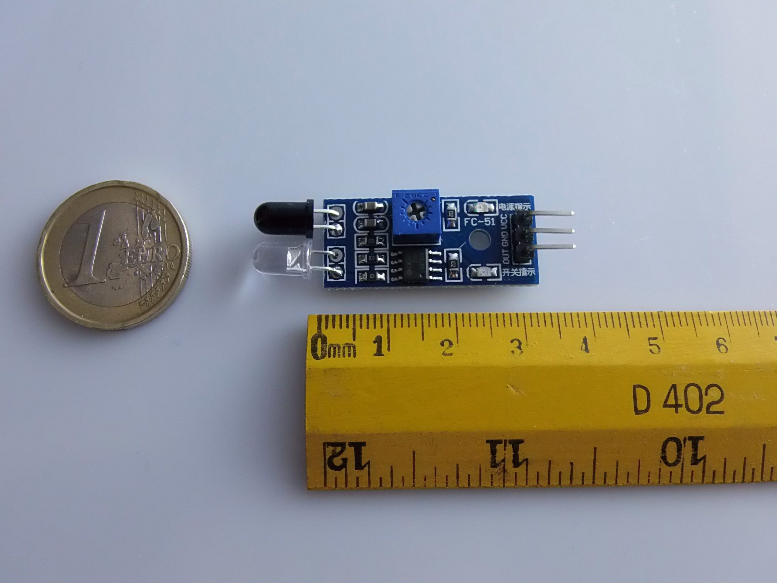
5 x 1.5 x 1.5 cm |
|
|
PACKAGE DIMENSIONS (L x W x H) |
5 x 3 x 2 cm |
|
|
PACKAGE CONTENTS |
PACKAGE CONTENTS |
1 x Module |
We have datasheets available for all components, if not present in the product download sheet, please send us a message through the contact form and we will publish it as soon as possible on our website.
Tutorial: How to Use Infrared Obstacle Avoidance Sensor Module
The infrared obstacle avoidance sensor module is ideal for obstacle avoidance projects with Arduino. It is perfect for both beginners and more experienced makers.
What you need
- Arduino Uno or compatible
- USB cable
- Power connection (5V and GND)
- Arduino IDE software
Steps
- Connect the VCC, GND pins of the sensor to the +5V and GND of the Arduino.
- Connect the OUT pin of the sensor to digital pin 2 of the Arduino.
- Open the Arduino IDE and upload the provided sketch.
- Check the distance detected by the sensor by changing the position of obstacles.
- Modify the sketch if necessary to adapt it to your project.
Example code
void setup() {
 pinMode(2, INPUT);
}

void loop() {
 int distanza = digitalRead(2);
 Serial.println(distanza);
}
Mini project
Create an obstacle-avoiding robot in 30 minutes. Use the infrared sensor to move a small vehicle while avoiding obstacles.
Common mistakes
- Do not verify the correct powering of the sensor (5V).
- Connect the OUT pin to a non-digital port on Arduino.
- Use distance values without first calibrating the sensor.
- Ignore the specifications on the datasheet.
Recommended accessories
- DC Motor for robot
- Kit wheels and axles for robot
- Prototype pin header
- Rechargeable batteries
Frequently asked questions
What is the maximum detection distance?
Check the sensor’s datasheet.
How can I increase the measurement accuracy?
Calibrate the sensor in various environments and lighting conditions.
Reviews
There are no reviews yet.