 EN
 IT Italiano
 ES Español
 FR Français
 DE Deutsch
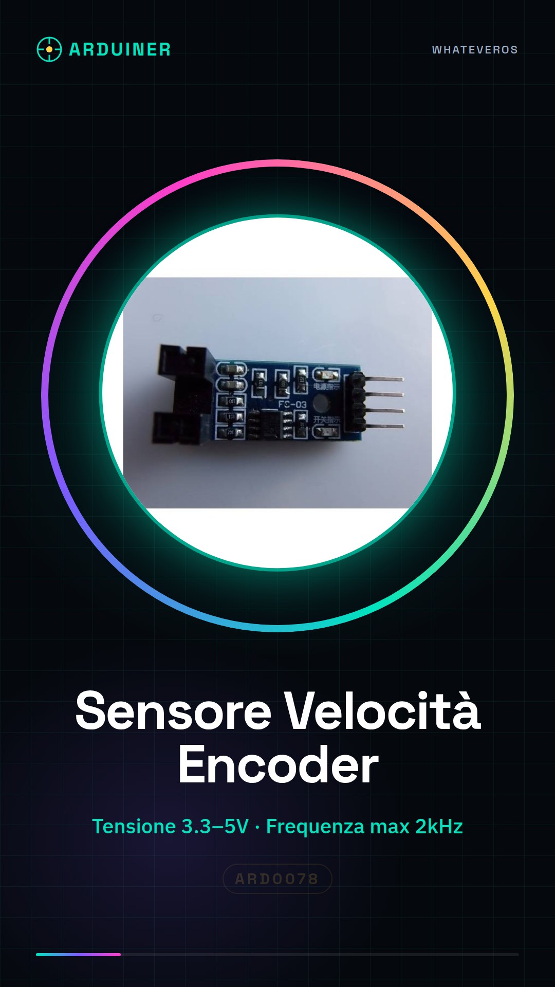
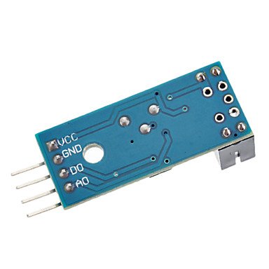
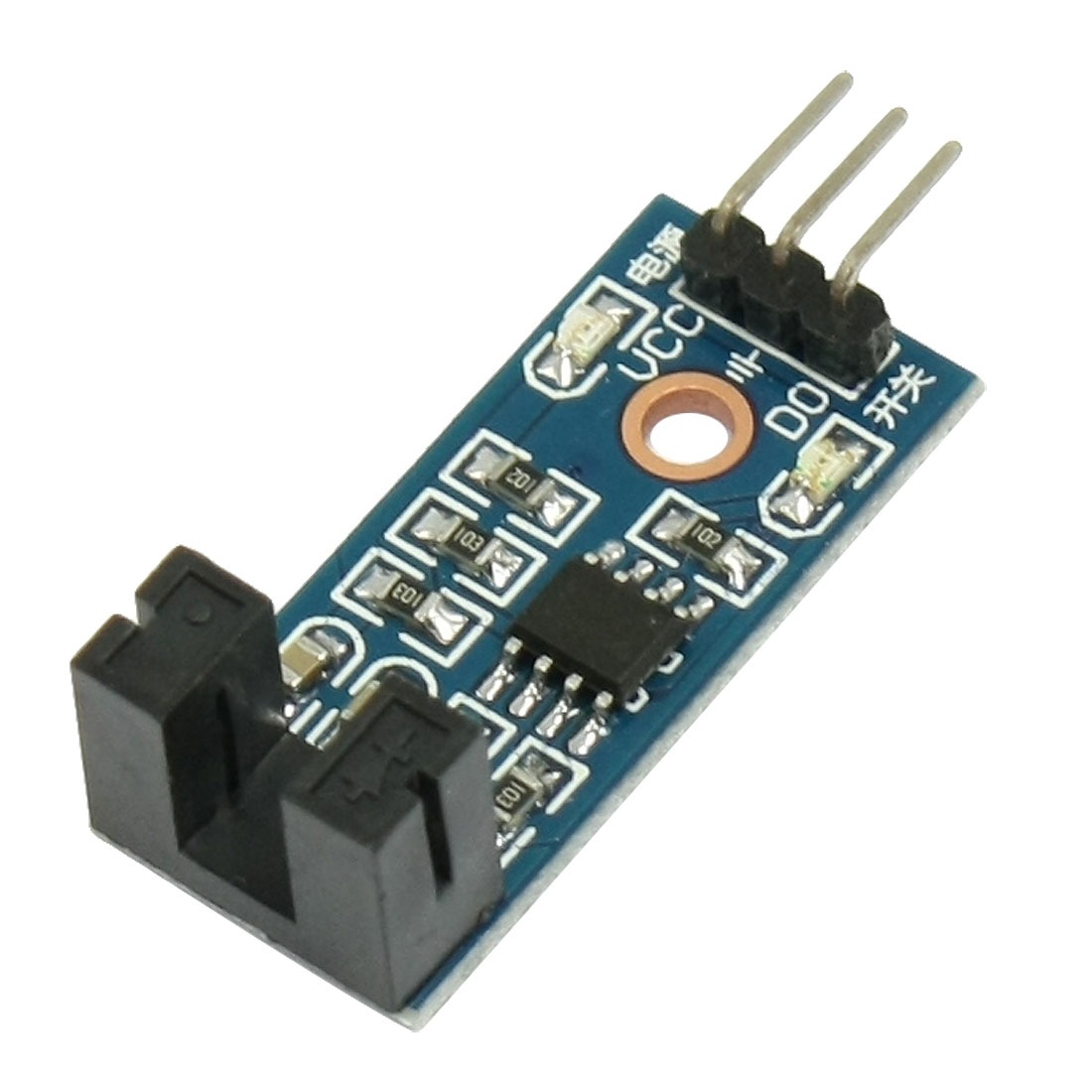
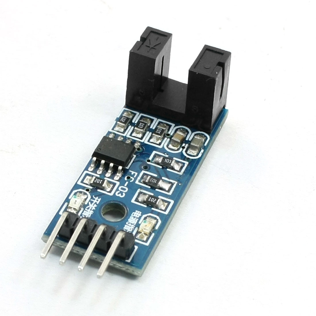
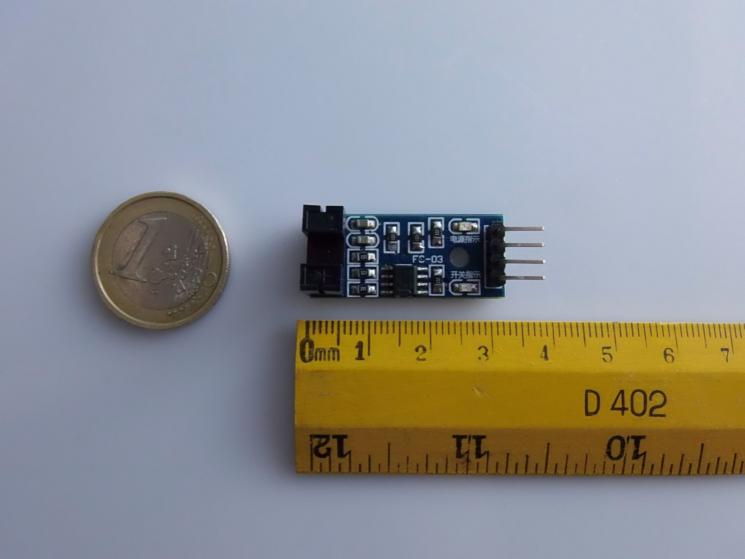
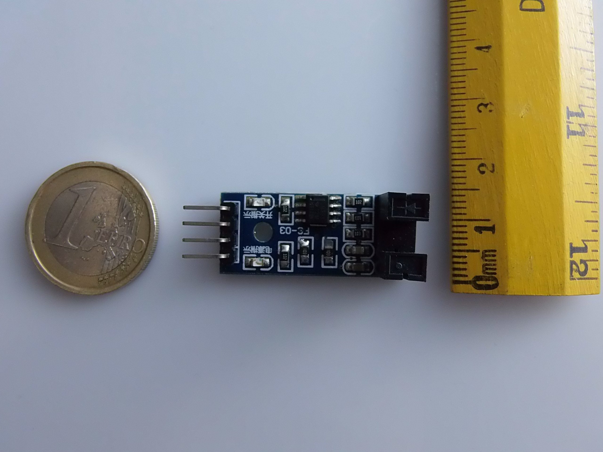
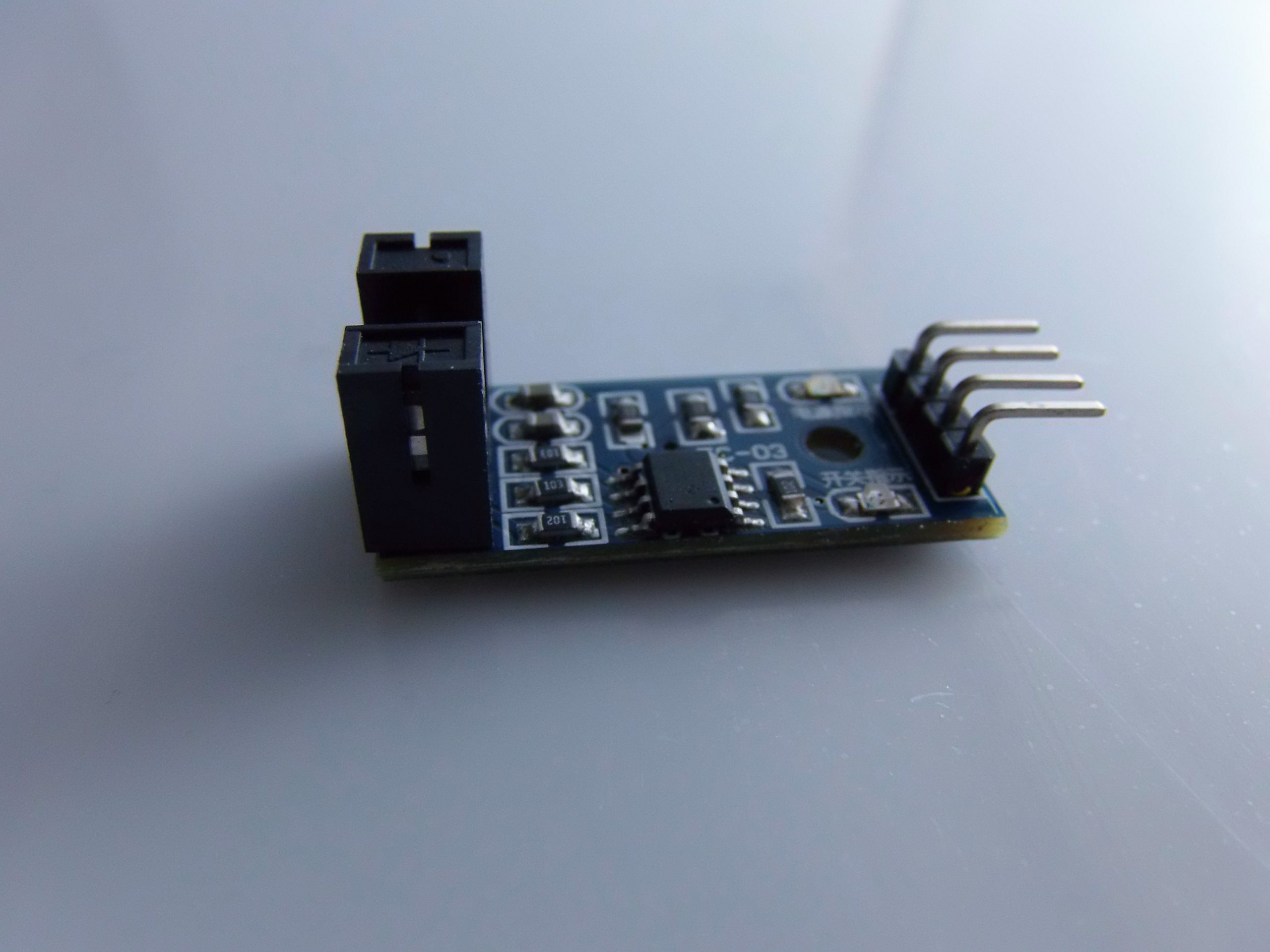
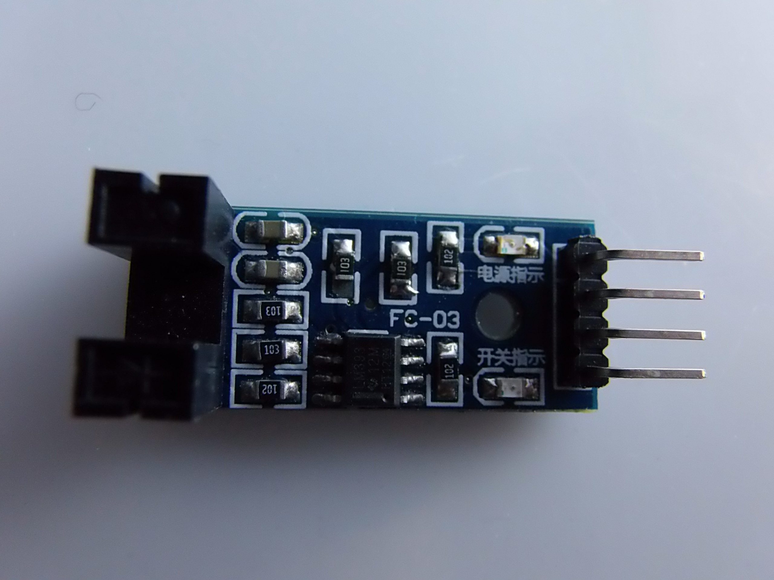
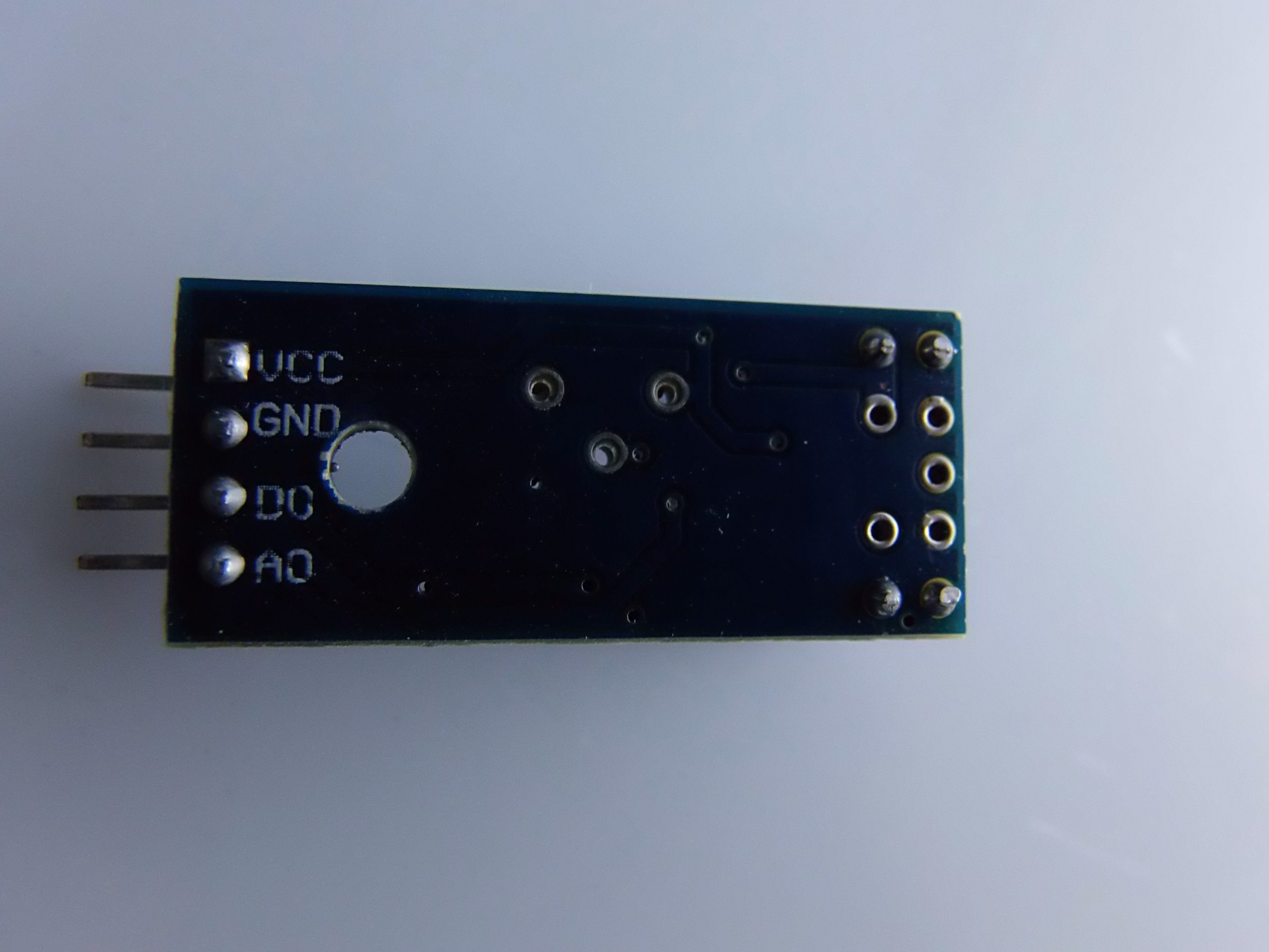
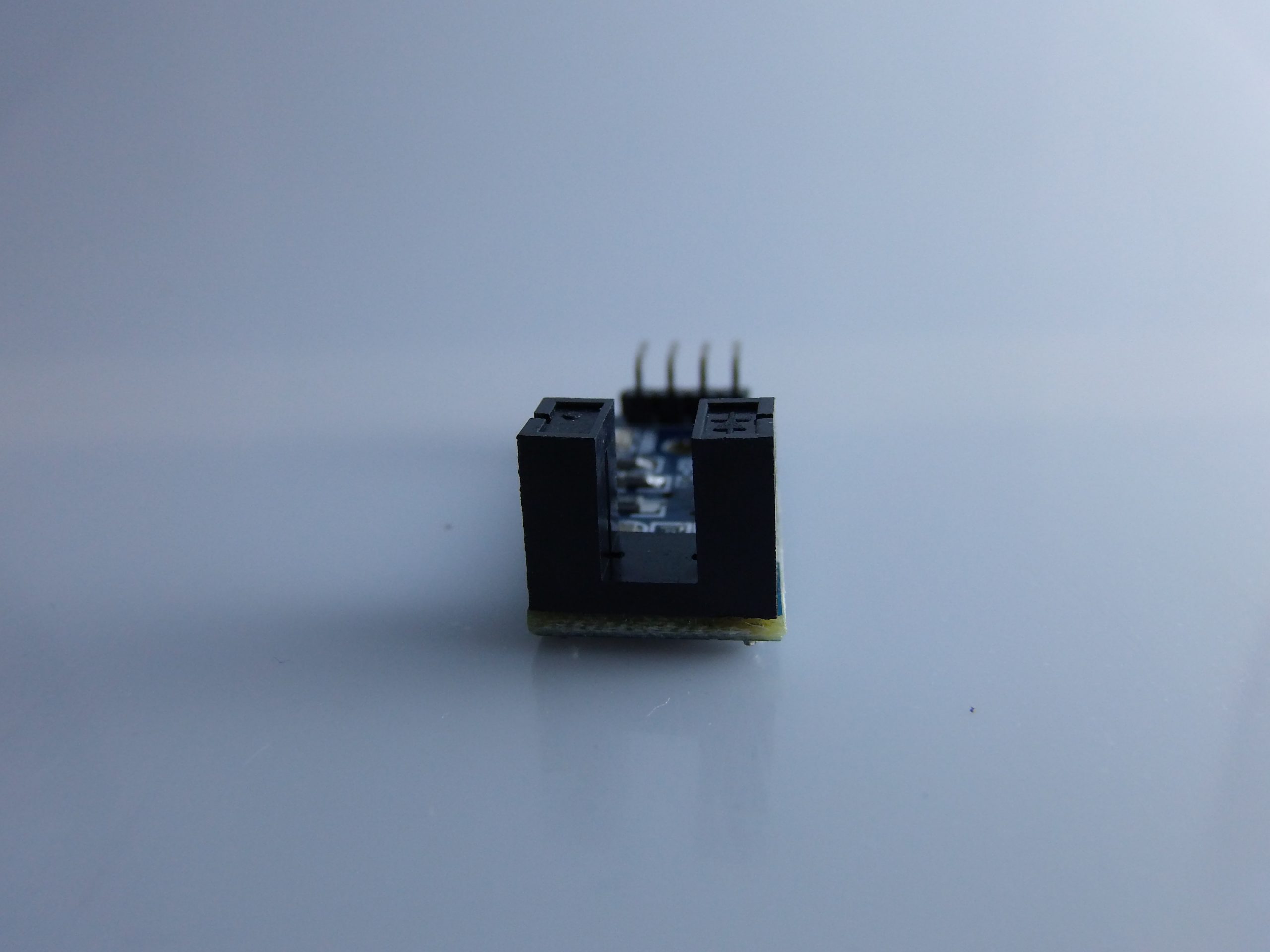
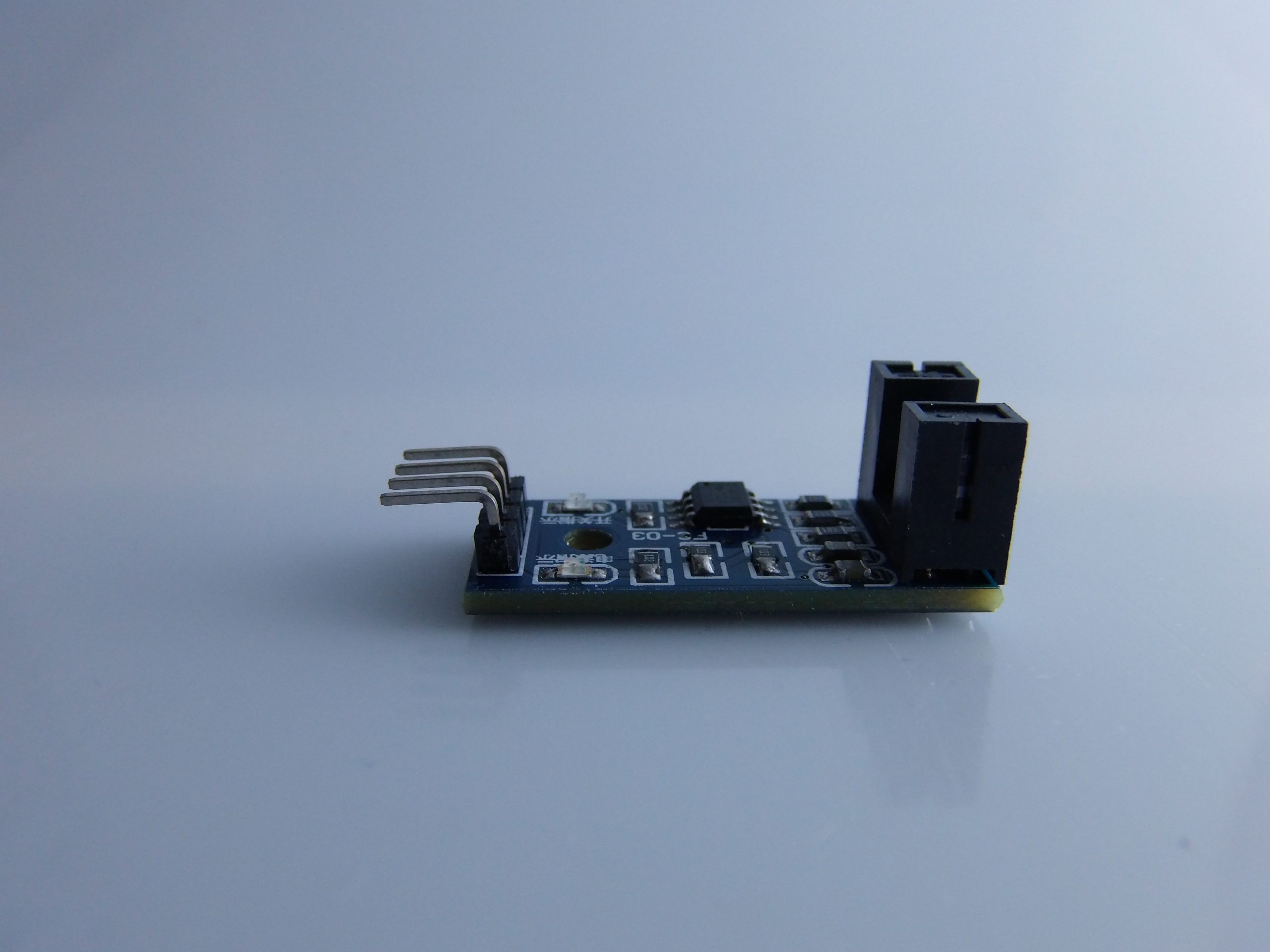
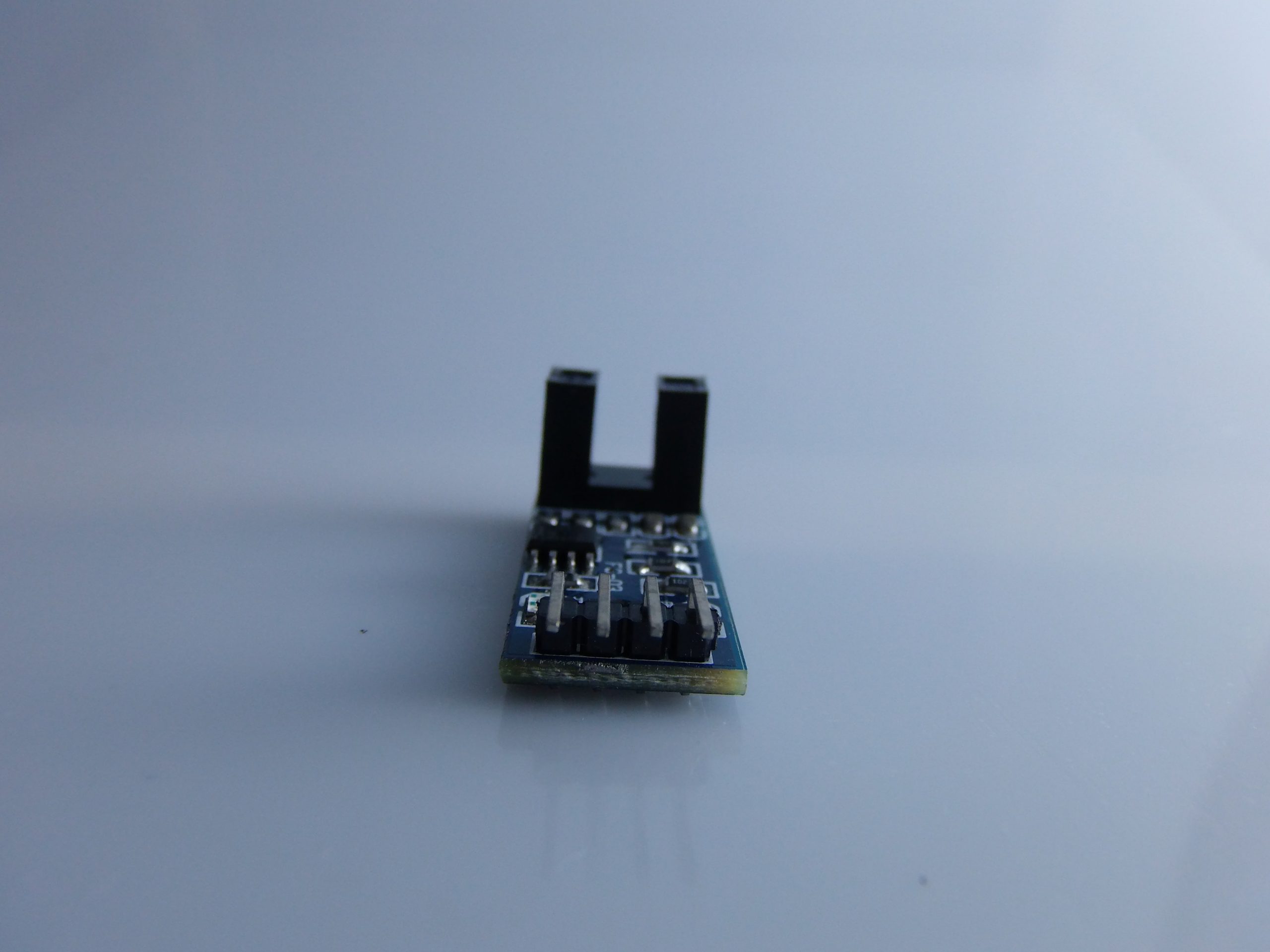
Description
⚙️ Digital Encoder Speed Sensor Module – Complete Description
✅ What is it?
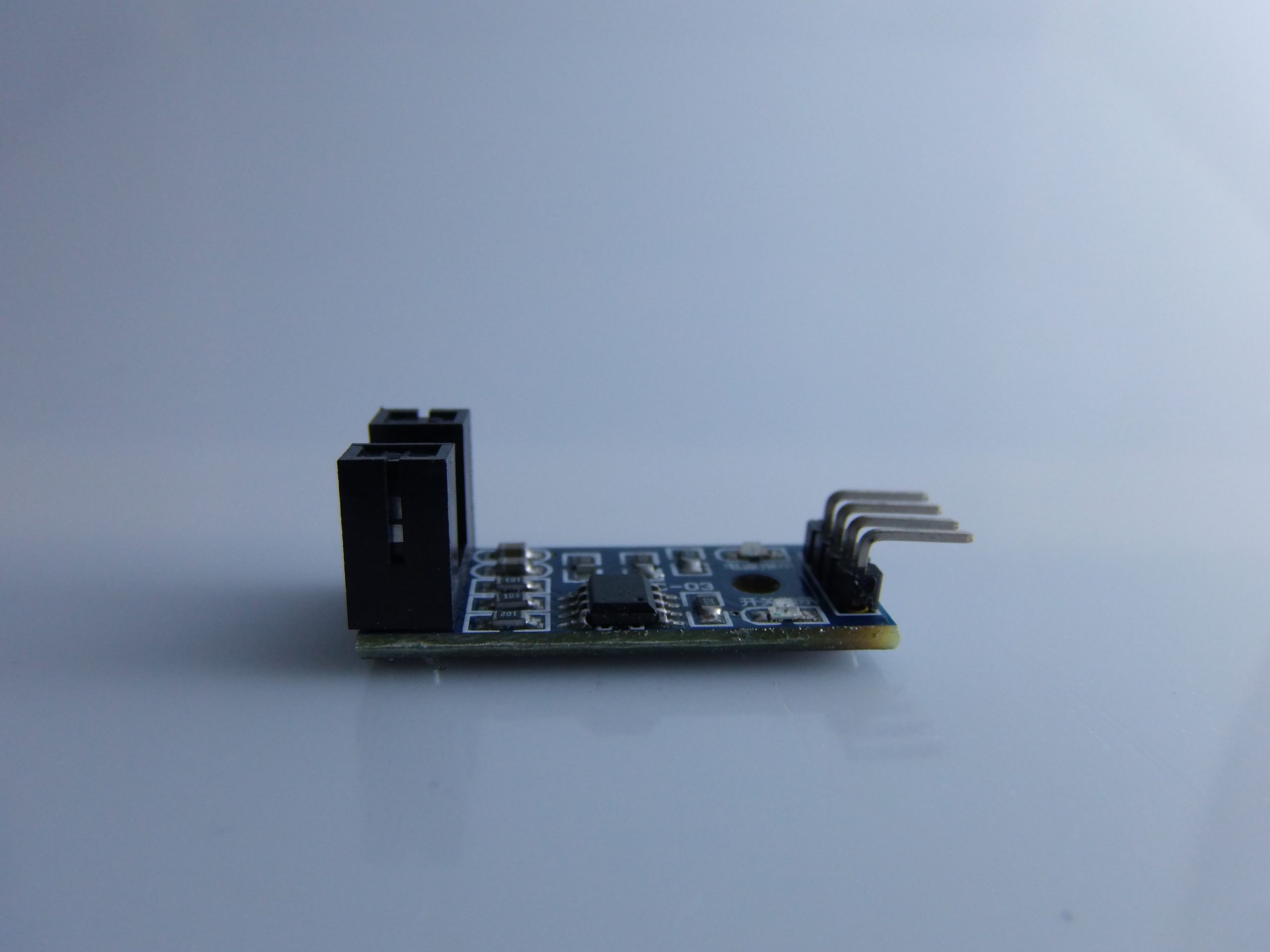
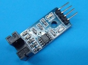
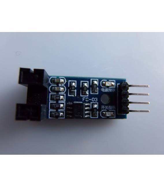
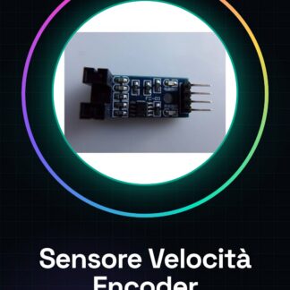
The Speed Sensor Module with digital encoder is a device designed to measure the angular velocity or rotation of an axis (e.g., drive wheels) using an infrared optical system. It is commonly used in mobile robots, rotation counting systems, and projects that require speed or distance measurement.
🔧 How it works
The module utilizes:
- An IR emitter (infrared LED)
- An IR receiver (phototransistor)
- A slotted or striped optical encoder disk
When the disk rotates, the holes or stripes interrupt the IR beam, generating digital pulses that Arduino can count to determine speed or distance.
🧩 Main components of the module
- IR emitter + receiver
- Comparators to clean the signal
- Digital square wave output (HIGH/LOW)
- Interface with 3 or 4 pins (VCC, GND, OUT, sometimes also A0)
- Mechanical support for shaft/disk
📦 Technical specifications
| Characteristic | Value |
|---|---|
| Operating voltage | 3.3V – 5V |
| Signal type | Digital (pulses) |
| Output | TTL (HIGH/LOW) |
| Max frequency | ~2kHz (depends on the disk) |
| Optical Sensor | Infrared (850–950nm) |
| Application | Count revolutions, speed, encoder |
🔌 Connection with Arduino
🧰 Materials
- Arduino Uno/Nano/Mega
- IR Encoder Module
- Perforated disk or wheel with black/white stripes
- Jumper wires
🖇️ Connection diagram
| Encoder Module | Arduino Pin |
|---|---|
| VCC | 5V |
| GND | GND |
| OUT | D2 (recommended, pin with interrupt) |
⚠ Important: connect OUT to a pin with interrupt hardware (D2 or D3 on Arduino Uno) for precise counting.
👨💻 Basic example code: pulse counting
volatile int impulsi = 0;

void setup() {
 pinMode(2, INPUT); // pin OUT encoder
 attachInterrupt(digitalPinToInterrupt(2), contaImpulso, RISING);
 Serial.begin(9600);
}

void loop() {
 Serial.print("Impulsi rilevati: ");
 Serial.println(impulsi);
 delay(1000);
}

void contaImpulso() {
 impulsi++;
}
Each pulse corresponds to an interruption of the IR beam, thus to a “window” of the disk.
📐 Speed and distance calculation
🧮 Formula (basic example):
velocita = (impulsi / numero_fessure) * (2 * PI * raggio) / tempo;
Where:
numero_fessure= number of holes/stripes on the diskraggio= wheel radius in meterstempo= time between two readings (in seconds)
🧪 Example: linear speed
#define FESSURE 20
#define RAGGIO_CM 3.0

volatile int impulsi = 0;
unsigned long tempoPrec = 0;

void setup() {
 pinMode(2, INPUT);
 attachInterrupt(digitalPinToInterrupt(2), contaImpulso, RISING);
 Serial.begin(9600);
}

void loop() {
 delay(1000); // campionamento ogni 1 sec

 noInterrupts();
 int conteggio = impulsi;
 impulsi = 0;
 interrupts();

 float giroRuota = 2 * PI * RAGGIO_CM / 100.0;
 float giri = (float)conteggio / FESSURE;
 float distanza = giri * giroRuota;
 float velocita = distanza / 1.0; // m/s, perché il tempo è 1 sec

 Serial.print("Velocità (m/s): ");
 Serial.println(velocita);
}
void contaImpulso() {
 impulsi++;
}
🔬 Testing and calibration
- Use a disk with known number of slots
- Measure the actual diameter of the wheel
- Check accuracy on known rotations (e.g., 1 full turn = 20 pulses)
- If the signal is unstable, add a decoupling capacitor or a software filter
🧠 Practical Applications
- 🚗 Mobile Robots: calculate distance traveled
- 📦 Conveyor Belts: count objects or length
- 🏎️ RC Cars / Autonomous Vehicles: speed control
- ⚙️ CNC Machines: encoder for motion axis
- ⏱️ Timing: speed measurements in experimental physics
📝 Conclusion
✅ The speed sensor with encoder is a versatile and easy-to-use tool
✅ Provides precise data on rotations, speed, and distance
✅ Essential for projects in robotics, automation, and mechanical engineering
Perfect! I provide you with:
✅ Pre-configured Arduino sketch
for Digital Speed Sensor Module with Encoder
🎯 Objective:
Measure impulses generated by the rotation of a wheel with an optical encoder and calculate the linear speed and the distance traveled in meters.
🧪 Complete Arduino sketch
// -------------------------------
// Modulo Encoder Velocità IR
// -------------------------------

#define ENCODER_PIN 2 // Collegato all'uscita digitale del modulo IR
#define NUM_FESSURE 20 // Numero di fessure/strisce sul disco
#define RAGGIO_RUOTA_CM 3.0 // Raggio della ruota in cm

volatile unsigned int impulsi = 0;
unsigned long tempoPrecedente = 0;
const unsigned long intervallo = 1000; // Tempo tra letture (ms)

void setup() {
 pinMode(ENCODER_PIN, INPUT);
 attachInterrupt(digitalPinToInterrupt(ENCODER_PIN), contaImpulsi, RISING);
 Serial.begin(9600);
 Serial.println("Sensore Encoder IR Avviato");
}

void loop() {
 unsigned long tempoAttuale = millis();

 if (tempoAttuale - tempoPrecedente >= intervallo) {
 noInterrupts(); // Disattiva gli interrupt per leggere in modo sicuro
 unsigned int conteggio = impulsi;
 impulsi = 0;
 interrupts(); // Riattiva gli interrupt

 // Calcolo della distanza e velocità
 float giri = (float)conteggio / NUM_FESSURE;
 float circonferenza = 2 * PI * RAGGIO_RUOTA_CM / 100.0; // in metri
 float distanza = giri * circonferenza; // in metri
 float velocita = distanza / (intervallo / 1000.0); // m/s

 Serial.print("Impulsi: ");
 Serial.print(conteggio);
 Serial.print(" | Distanza: ");
 Serial.print(distanza, 3);
 Serial.print(" m | Velocità: ");
 Serial.print(velocita, 3);
 Serial.println(" m/s");

 tempoPrecedente = tempoAttuale;
 }
}

void contaImpulsi() {
 impulsi++;
}
🧰 Required components for Tinkercad simulation
- Arduino Uno
- Speed sensor module (IR encoder)
- Simulated encoder disk (can be a button if the disk is not available)
- Jumper cables
- (Optional) DC motor with wheel
🔧 Simulation in Tinkercad (alternative if you don’t have the disk):
You can simulate the sensor using a button or infrared sensor connected to pin D2, and each press simulates a “pulse”.
Connection:
| Component | Arduino |
|---|---|
| OUT sensor (or button) | D2 |
| VCC | 5V |
| GND | GND |
|
GENERAL |
MODEL |
detector of |
|
MATERIALS |
pcb + components |
|
|
COMPATIBILITY |
ARDUINO |
|
|
ELECTRICAL COMPONENTS |
INPUT VOLTAGE |
3,3-5V |
|
WEIGHT AND DIMENSIONS |
PRODUCT WEIGHT |
7g |
|
PACKAGE WEIGHT |
0.085 kg |
|
|
PRODUCT DIMENSIONS (L x W x H) |
4 x 1.5 x 2 cm |
|
|
PACKAGE DIMENSIONS (L x W x H) |
5 x 3 x 3 cm |
|
|
PRODUCT CONTENT |
PRODUCT CONTENT |
1 x Module |
We have the technical sheet of all components available, should it not be present in the product download sheet, send us a message via the contact form and we will publish it as soon as possible on our website.
Tutorial: How to Use the Speed Sensor Module
The Speed Sensor Module with digital encoder is ideal for measuring the rotational speed of a motor or rotating device. Useful for robotics and automation projects.
What you need
- Arduino UNO or compatible
- Electrical Filters (R/C)
- 5V Power Cable
- Data Cable (for I/O pins)
Steps
- 1. Connect the module to the Arduino via the GND, 5V, D2 and D3 pins.
- 2. Mount an electrical filter between 5V and GND to protect the module.
- 3. Connect the 5V power cable to the module.
- 4. Connect the data cable to pin D2 and D3.
- 5. Load the Arduino IDE.
- 6. Enter the example code provided.
- 7. Upload the code to Arduino.
- 8. Check the displayed rotation speed on the serial monitor.
Example code
```cpp
#include <Encoder.h>

Encoder myEncoder(D2, D3);

void setup() {
 Serial.begin(9600);
}

void loop() {
 Serial.println(myEncoder.read());
}
```
Mini project
Create a speed control device for a DC motor using the module and Arduino.
Common mistakes
- Omit connecting the electrical filter.
- Connect the pins incorrectly.
- Forget to upload the code.
- Do not check the pin connectivity before uploading the code.
Recommended accessories
- DC Motors
- Arduino UNO
- Electrical Filter (R/C)
- 5V Power Cable
Frequently asked questions
Does the module work with a power supply different from 5V?
Check the datasheet. Other power supplies may require a converter.
Which Arduino pins should I use?
Use pins D2 and D3 to connect the module.
Does the module work with Arduino compatible boards?
Yes, but make sure the power supply is compatible with 5V.
How can I check the connection?
Check the serial console after uploading the code.
Reviews
There are no reviews yet.