 EN
 IT Italiano
 ES Español
 FR Français
 DE Deutsch
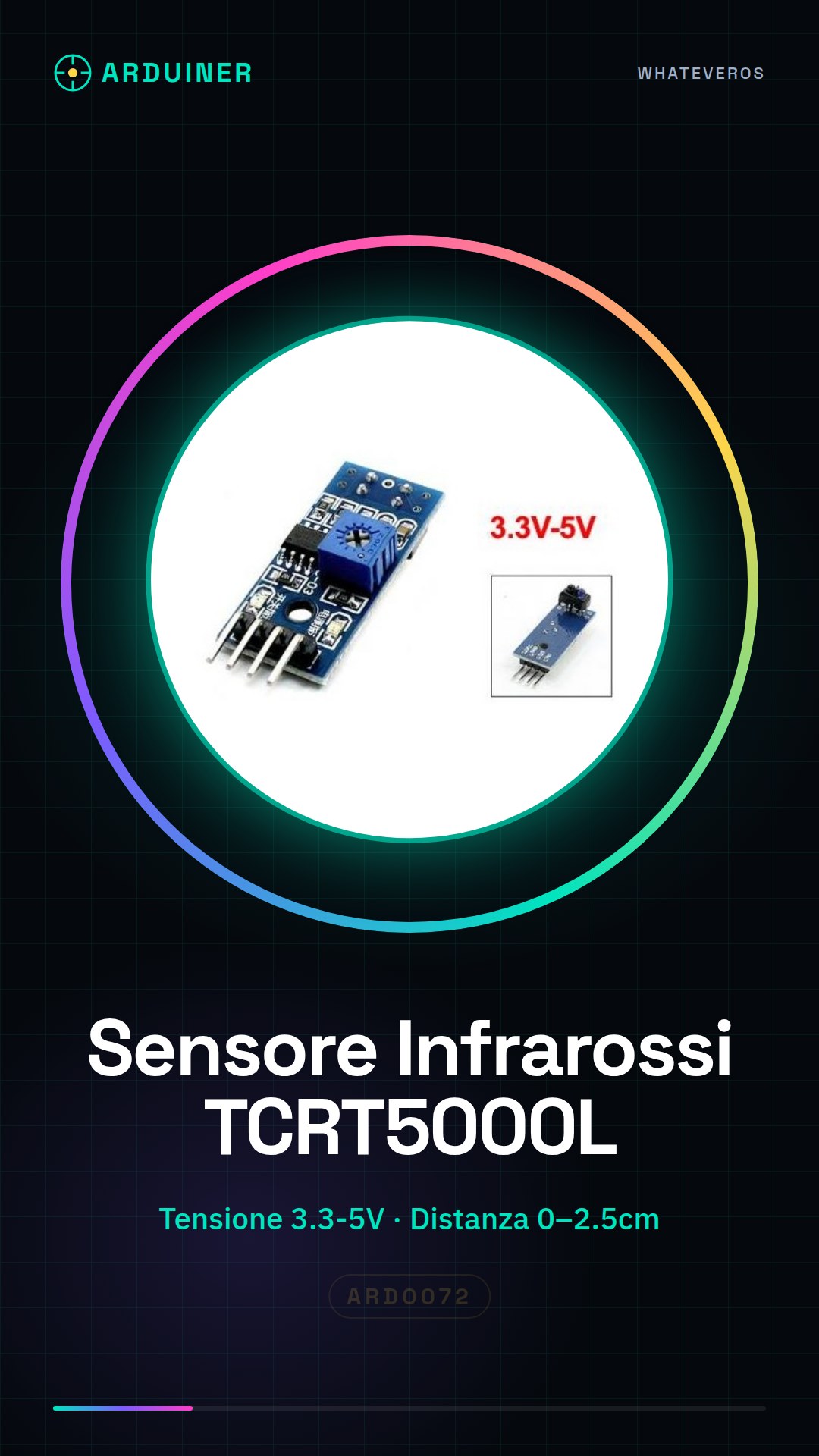
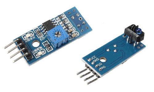
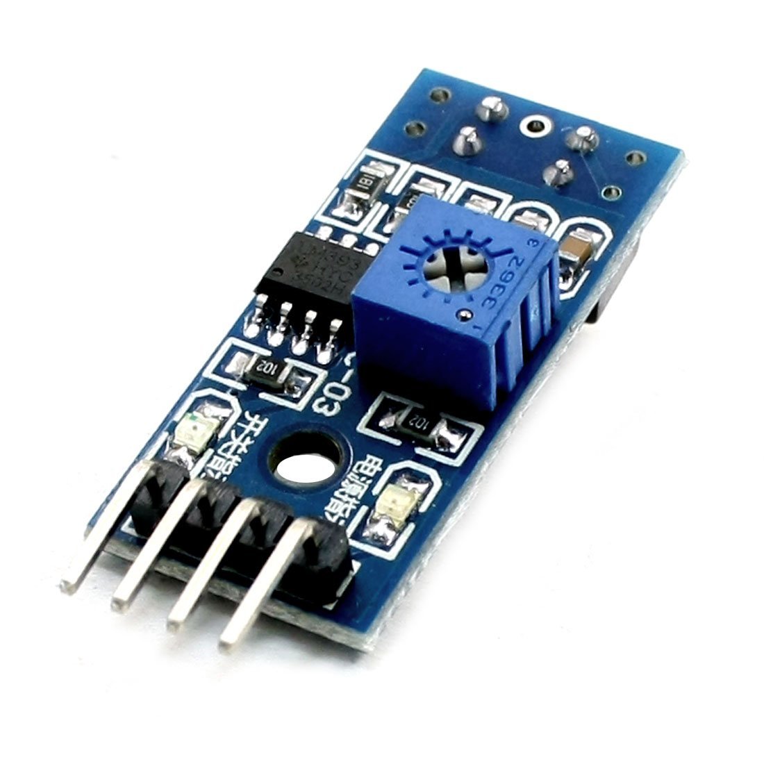
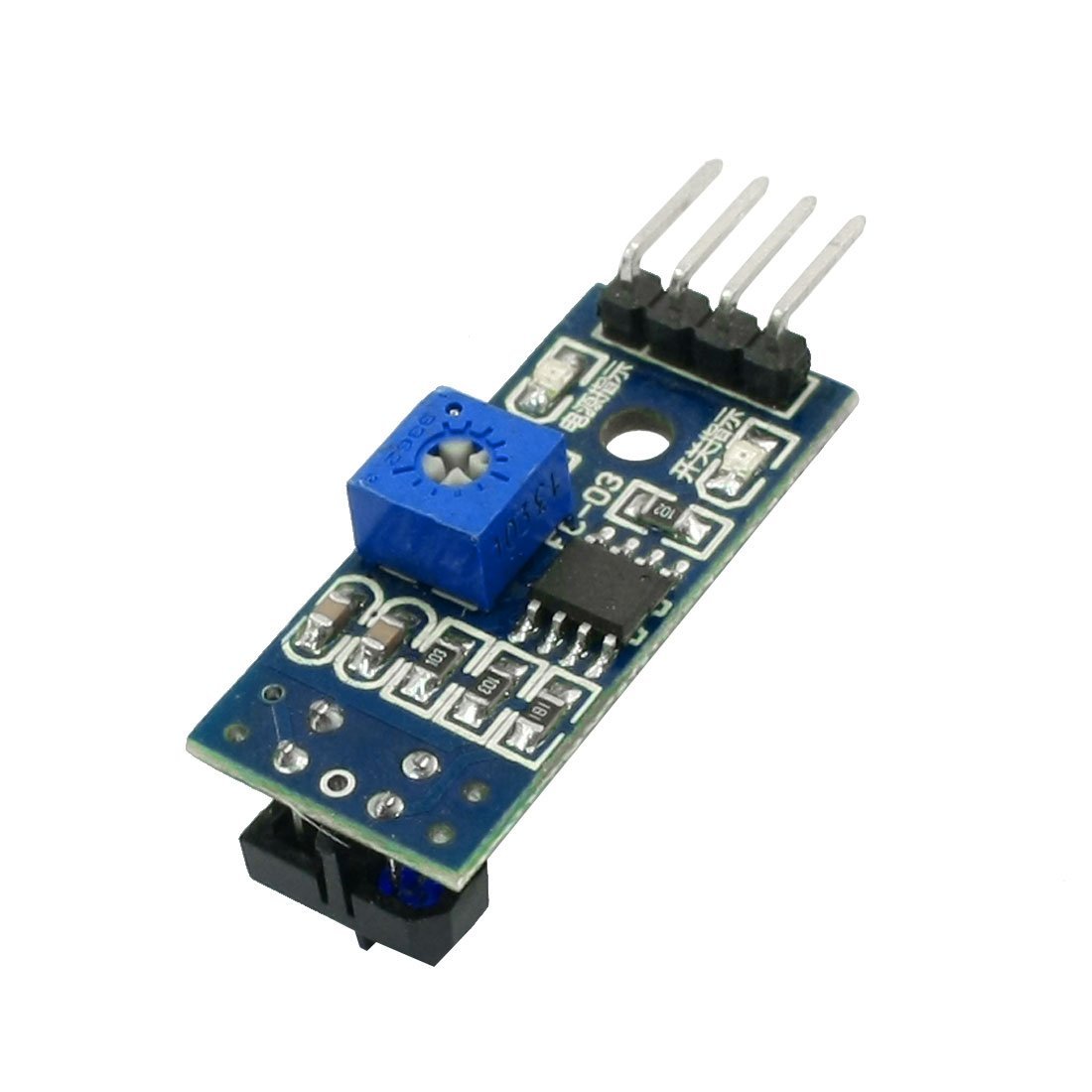
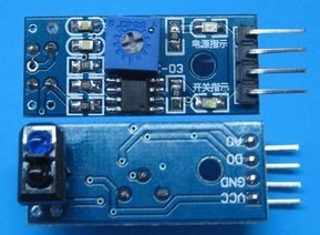
Description
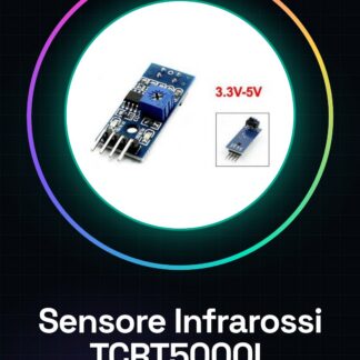
🔍 Infrared Line Sensor Module TCRT5000L – Line Follower Detector for Arduino
✅ General Description
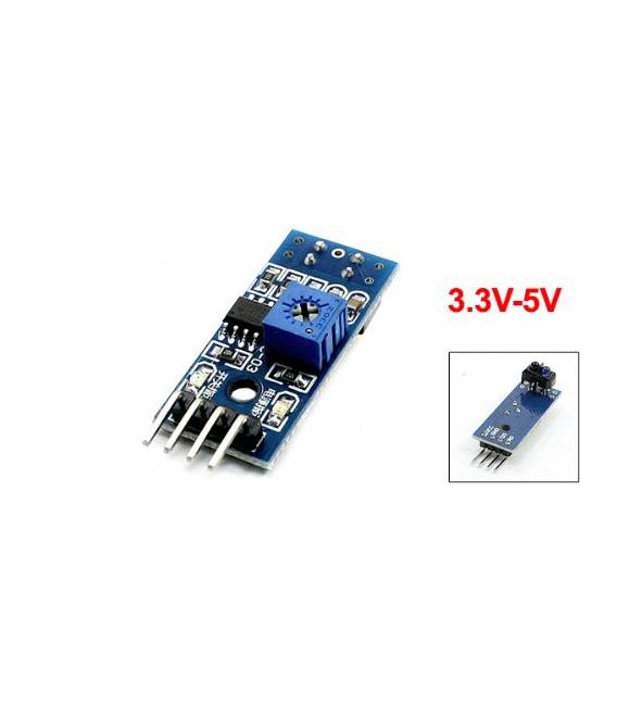
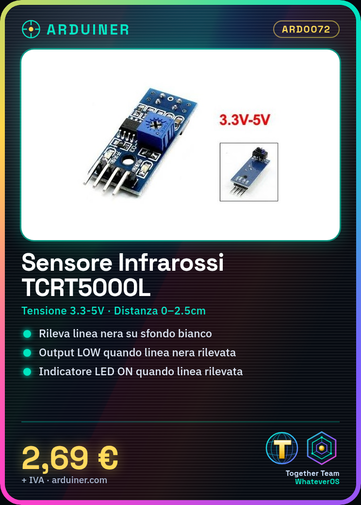
The TCRT5000L module is an infrared reflective sensor, designed to detect black lines on a white background (or vice versa), nearby obstacles, or reflectance variations. It is widely used in line follower robots, object counting systems, tachometers, and proximity detection applications.
⚙️ Technical Specifications
| Characteristic | Specification |
|---|---|
| Optical Sensor | TCRT5000L (IR LED + phototransistor) |
| Operating Distance | 0 – 2.5 cm (optimal < 1 cm) |
| Supply Voltage | 3.3V – 5V |
| Output | Digital (LOW = black line detected) |
| Indicator LED | ON when the line is detected |
| Dimensions | Compact, suitable for mobile robots |
| Threshold Adjustment | No (base model) – fixed threshold |
| Compatibility | Arduino, ESP32, Raspberry Pi, STM32, etc. |
📌 The sensor emits infrared and measures the amount reflected: more reflected (light surface) → HIGH; less reflected (dark line) → LOW.
🧪 How It Works
The sensor TCRT5000L has an IR LED and a phototransistor:
- Light surface: reflects IR → phototransistor receives → output = HIGH
- Dark surface (e.g., black line): absorbs IR → output = LOW
🧰 Connection with Arduino
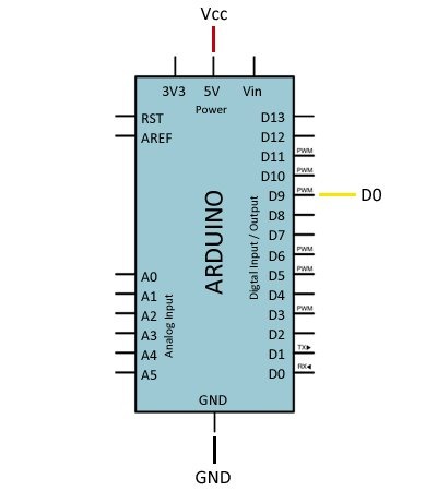
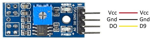
🔌 Connection Diagram
| Module Pin | Arduino Connection |
|---|---|
| VCC | 5V |
| GND | GND |
| OUT | Ex. D2 |
💻 Arduino Programming
📜 Basic Example: Line Follower
const int pinSensore = 2; // OUT del modulo
void setup() {
  Serial.begin(9600);
  pinMode(pinSensore, INPUT);
}

void loop() {
  int stato = digitalRead(pinSensore);
  if (stato == LOW) {
    Serial.println("Linea NERA rilevata");
  } else {
    Serial.println("Superficie CHIARA");
  }
  delay(200);
}
⚠️ The sensor does not return analog values, but a digital HIGH/LOW signal.
🤖 Common Applications
- 🤖 Line Follower Robot (black line detection)
- 📦 Object Counting (IR beam interruption)
- ⚙️ Optical Tachometers (reading marks on wheel)
- 🛑 Fall Detection Sensors (margin or different surface recognition)
🔄 Example: Robot with 2 sensors to follow a line
Sensors connected to D2 and D3
#define SINISTRA 2
#define DESTRA 3

void setup() {
  pinMode(SINISTRA, INPUT);
  pinMode(DESTRA, INPUT);
  Serial.begin(9600);
}

void loop() {
  int sx = digitalRead(SINISTRA);
  int dx = digitalRead(DESTRA);

  if (sx == LOW && dx == LOW) {
    Serial.println("Entrambi sulla linea");
    // avanti
  } else if (sx == LOW && dx == HIGH) {
    Serial.println("Curva a sinistra");
    // gira sinistra
  } else if (sx == HIGH && dx == LOW) {
    Serial.println("Curva a destra");
    // gira destra
  } else {
    Serial.println("Linea persa");
    // fermati o cerca linea
  }
  delay(100);
}
🛠 Usage Tips
- Maintain the distance between sensor and surface around 5 – 10 mm.
- Avoid too intense ambient light (affects reflectivity).
- For dynamic use (robots), mechanical tuning and empirical testing are essential.
- If you want analog values, there are versions with output AO adjustable with potentiometer.
📚 Possible Extensions
- 📏 Speed calculation: detecting sequential passes
- 🖱️ Touchless switch: activate events with your hand in front of the sensor
- 🔄 Encoder rotation: reading of alternating white/black patterns on a disk
✅ Conclusion
The TCRT5000L Module is a simple, economical, and precise sensor for detecting lines, surfaces, objects, and obstacles at short distances. Perfect for:
- Educational or competition robots
- Automatic counters
- Reflective Sensors
📦 Want one too?
- 🧠 Fritzing Schematic with multiple sensors on a robot?
- 📲 Wi-Fi Integration to send counts to smartphone?
- 📁 Log data to SD card?
- 🖥️ Display on OLED or LCD?
Here is a complete project that integrates the TCRT5000L module with multi-sensor functionality on a robot, Wi-Fi to send counts to smartphone, log to SD card e display on OLED or LCD.
🧩 1. Fritzing Schematic with multiple sensors on robot
Use 3 or more TCRT5000L modules mounted on the front of the robot to follow the line. Each sensor has VCC, GND, and OUT connected to digital pins (e.g., D2, D3, D4…). The signals go to the INPUT pins of the Arduino/Nano.
An example of Fritzing schema with 3 TCRT5000 mounted on robot it is available in various educational projects and allows line direction detection based on which sensor reads line black (dyor.webs.upv.es, instructables.com).
📡 2. Wi-Fi Integration to send counts to smartphone
Uses a module ESP32 or NodeMCU (ESP8266) to count events (e.g., crossings on the line) and publish them via a local web page, accessible from smartphone.
Based on Arduino forums and resources, the philosophy is: run a web server on the ESP module, which shows the data in real-time to the user via mobile browser (forum.arduino.cc, reddit.com).
📁 3. Log data to SD card
Connect a module microSD SPI and write the count or digital readings to a CSV file. Use the library SD.h to save timestamp and value to external memory.
🖥️ 4. Display on OLED or LCD
Install a display OLED 128×64 I2C (SSD1306) or an LCD I2C 16×2. It will show in real-time:
- the number of lines detected,
- sensor status (e.g., “left line”, “center line”…),
- battery voltage, time, etc.
📋 Hardware Connections Summary
| Function | Components | Main Connections |
|---|---|---|
| Line follower | 3× TCRT5000L | VCC‑5V, GND‑GND, OUT → D2, D3, D4 |
| Wi-Fi / Web server | ESP32 or NodeMCU | Sensors connected to GPIO, power supply 5V / 3.3V |
| Data logging | microSD module (CS for example D5) | CS on D5, MISO MOSI SCK on SPI, CSV file width |
| Display | OLED SSD1306 (I2C) | SDA → A4, SCL → A5 (I2C), display via Adafruit_SSD1306 |
📜 Example Code (ESP32 + Web Server + OLED + SD)
#include <WiFi.h>
#include <WebServer.h>
#include <SPI.h>
#include <SD.h>
#include <Wire.h>
#include <Adafruit_SSD1306.h>

#define SEN_LEFT 2
#define SEN_CENTER 3
#define SEN_RIGHT 4
#define SD_CS 5

WebServer server(80);
Adafruit_SSD1306 display(128, 64, &Wire);
int countLines = 0;

void handleRoot(){
  server.send(200, "text/html",
    "<h1>Conteggio linee: "+String(countLines)+"</h1>");
}

void setup(){
  Serial.begin(115200);
  pinMode(SEN_LEFT,INPUT);
  pinMode(SEN_CENTER,INPUT);
  pinMode(SEN_RIGHT,INPUT);

  // Wi-Fi
  WiFi.begin("SSID","PASSWORD");
  while(WiFi.status()!=WL_CONNECTED) delay(500);
  server.on("/", handleRoot);
  server.begin();

  // SD card
  if(!SD.begin(SD_CS)) Serial.println("SD err");
  // OLED
  display.begin(SSD1306_SWITCHCAPVCC, 0x3C);
  display.clearDisplay(); display.setTextSize(2);
}

void loop(){
  server.handleClient();
  int sC = digitalRead(SEN_CENTER);
  static int last = HIGH;
  if(sC==LOW && last==HIGH){
    countLines++;
    File f = SD.open("log.csv", FILE_APPEND);
    if(f){ f.println(String(millis()/1000)+","+countLines); f.close(); }
  }
  last = sC;

  display.clearDisplay();
  display.setCursor(0,0);
  display.print("Cnt:"); display.println(countLines);
  display.display();
  delay(100);
}
🧠 Useful Tips
- 📐 Test various sensor/surface distances (3–10 mm)
- 🧼 Use an array of 3 sensors for stability on curves
- 🧪 Test empirical calibrations
- 🔌 Stable power supply
- 📶 If push notifications or graphs are needed, you can extend with Blynk, MQTT o Telegram Bot
✅ Conclusion
The proposed project includes:
- Fritzing schema with multiple array of TCRT5000L sensor on robot.
- Wi-Fi web server for counts accessible from smartphone.
- Log on SD card for subsequent analysis.
- OLED display for real-time visual feedback.
We have datasheets of all components available, should it not be present in the product download sheet, send us a message from the contact us module and we will publish it as soon as possible on our website.
Tutorial: How to use Infrared Sensor Module TCRT5000L
The infrared sensor module TCRT5000L is ideal for detecting objects or lines on a plane. It is perfect for robotics projects, interactive games, and security systems.
What you need
- Arduino Uno
- USB cable
- Velcro connections
Steps
- Connect the VCC and GND pins of the module to +5V and GND of the Arduino respectively.
- Connect the OUT pin of the sensor to digital pin 2 of Arduino.
- Open the Arduino IDE and upload the provided sketch to test the detection.
- Place an object in front of the sensor to see if it changes the logical state on Arduino.
- Check the minimum and maximum detection distance of the sensor by consulting the datasheet.
- Modify the sketch to adapt it to the specific requirements of your project.
- Try connecting multiple sensors in parallel using a multiplexer.
- Implement data reading from the sensor in an infinite loop and display the values on the serial monitor.
Example code
void setup() {
  pinMode(2, INPUT);
}

void loop() {
  if(digitalRead(2) == HIGH){
    Serial.println("Oggetto rilevato!");
  }
}
Mini project
Create a robot that follows a black line on a white plane using this sensor. Try programming the robot’s path and see how it reacts.
Common mistakes
- Do not connect VCC to the pin 3V3 of the Arduino, use only +5V.
- Ensure that the object to be detected is sufficiently close to the sensor to obtain a clear signal.
- Check the polarity of the connectors during connection.
- Don’t forget to add pull-up or pull-down resistors if necessary.
Recommended accessories
- Arduino Uno
- Velcro Connections
- CD4051 Multiplexer
- Line Follower Robot Kit
Frequently asked questions
What is the detection range of the sensor?
Check the datasheet.
Can I connect multiple sensors together?
Yes, but you will need to use a multiplexer to manage the input signals.
Reviews
There are no reviews yet.