 EN
 IT Italiano
 ES Español
 FR Français
 DE Deutsch
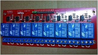
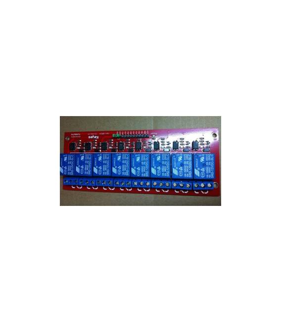
Description
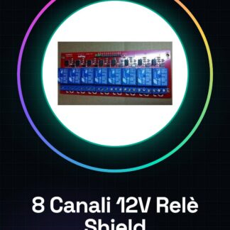
🔧 Description of the 8 Channel 12V Relay Shield (SRD-12VDC-SL-C) Module
✅ Main Features
- Module Type: Relay Shield
- Number of Channels: 8
- Operating Voltage: 12V DC
- Relays Used: SRD-12VDC-SL-C
- Relay Current: up to 10A at 250V AC / 10A at 30V DC
- Control Interface: 5V TTL compatible with microcontrollers (Arduino, PIC, ARM, AVR, DSP)
- Active Signal: Generally active LOW (negative logic)
- Isolation: Optically isolated with optoisolators for interference protection
- Status LED: An LED for each channel to indicate the relay status (on/off)
- Screw terminals: for safe connection of external loads
- Control pins: IN1–IN8
🔌 Hardware Connections
🛠️ Module pins
- VCC: 5V power supply for the relay logic (connect to Arduino’s 5V)
- GND: common ground
- JD-VCC: power supply for the relay circuit (12V required)
- IN1-IN8: relay control inputs (connected to Arduino’s digital pins)
🔐 Important Note: to properly isolate the module from Arduino, you can remove the jumper between VCC e JD-VCC, and provide 12V separately on JD-VCC (for relays) and 5V on VCC (for optoisolation).
🖥️ Connection Diagram with Arduino UNO
Modulo Relè Arduino UNO
----------- ------------
IN1 → Pin 2
IN2 → Pin 3
IN3 → Pin 4
IN4 → Pin 5
IN5 → Pin 6
IN6 → Pin 7
IN7 → Pin 8
IN8 → Pin 9
GND → GND
VCC → 5V
JD-VCC → +12V (alimentazione esterna per relè)
📘 Programming Guide with Arduino
✅ Basic Code to Control 8 Relays
// Pin di controllo dei relè
int rele[8] = {2, 3, 4, 5, 6, 7, 8, 9};

void setup() {
 for (int i = 0; i < 8; i++) {
 pinMode(rele[i], OUTPUT);
 digitalWrite(rele[i], HIGH); // Relè disattivi (attivo LOW)
 }
}

void loop() {
 // Accende tutti i relè uno alla volta
 for (int i = 0; i < 8; i++) {
 digitalWrite(rele[i], LOW); // Relè attivo
 delay(500);
 digitalWrite(rele[i], HIGH); // Relè disattivo
 }

 // Aspetta un secondo prima di ricominciare
 delay(1000);
}
💡 Examples of Applications
- Home Automation: turning on/off lights, fans, pumps.
- Industrial Load Control: management of solenoids or motors.
- IoT Projects: remote management of multiple devices via WiFi/Bluetooth.
- Irrigation System: turning on solenoids at scheduled times.
🔐 Safety Tips
- Do not exceed the current/voltage limits of the relays.
- Isolate AC loads with appropriate protections (fuses, varistors, etc.).
- If you control high voltage loads (220V AC), act with caution or get help from a qualified technician.
🧪 Quick Relay Test
To verify that the relays work correctly:
- Connect the INx pins to GND → the corresponding relay should activate (click should be heard).
- Use the code above to run a sequence.
🧰 Recommended Power Supply
- Use an external power supply from 12V 1-2A for JD-VCC.
- Use the jumper only if powering everything from Arduino, but this is not recommended if you use more than 2 relays simultaneously.
📦 Module Contents (for sale)
- 1x 8-channel 12V relay module (SRD-12VDC-SL-C)
- Screw terminals for loads
- Pin header for connection with Arduino
🔌 1. Control Relay via Serial Communication from PC
🎯 Objective:
Control the 8 relays from a PC via the Arduino serial port (using commands like ON1, OFF2, ALLON, ALLOFF).
📟 Arduino Code (Serial)
int rele[8] = {2, 3, 4, 5, 6, 7, 8, 9};
String inputString = "";

void setup() {
 Serial.begin(9600);
 for (int i = 0; i < 8; i++) {
 pinMode(rele[i], OUTPUT);
 digitalWrite(rele[i], HIGH);
 }
 Serial.println("Sistema pronto. Comandi: ONx / OFFx / ALLON / ALLOFF");
}

void loop() {
 if (Serial.available()) {
 char inChar = (char)Serial.read();
 if (inChar == 'n') {
 inputString.trim();
 processCommand(inputString);
 inputString = "";
 } else {
 inputString += inChar;
 }
 }
}

void processCommand(String cmd) {
 cmd.toUpperCase();

 if (cmd == "ALLON") {
 for (int i = 0; i < 8; i++) digitalWrite(rele[i], LOW);
 Serial.println("Tutti i relè ACCESI");
 } else if (cmd == "ALLOFF") {
 for (int i = 0; i < 8; i++) digitalWrite(rele[i], HIGH);
 Serial.println("Tutti i relè SPENTI");
 } else if (cmd.startsWith("ON")) {
 int ch = cmd.substring(2).toInt();
 if (ch >= 1 && ch <= 8) {
 digitalWrite(rele[ch - 1], LOW);
 Serial.println("Relè " + String(ch) + " acceso");
 }
 } else if (cmd.startsWith("OFF")) {
 int ch = cmd.substring(3).toInt();
 if (ch >= 1 && ch <= 8) {
 digitalWrite(rele[ch - 1], HIGH);
 Serial.println("Relè " + String(ch) + " spento");
 }
 } else {
 Serial.println("Comando non valido");
 }
}
🖥️ How to use it
Open the Arduino Serial Monitor at 9600 baud, send:
ON1→ turns on relay 1OFF1→ turns off relay 1ALLON→ turns on allALLOFF→ turns off all
🌐 2. WiFi Relay Control with ESP8266/ESP32 (Web Server)
🎯 Objective:
Control the relays from a local web page hosted by the WiFi module (ESP8266 or ESP32).
🧠 Requirements
- ESP8266 (e.g., NodeMCU) or ESP32
- 12V to the relay module, 5V logic (the INx pins of the module must accept 3.3V if using ESP8266)
- WiFi network
📟 Web Server Code (ESP8266)
#include <ESP8266WiFi.h>
const char* ssid = "TUO_SSID";
const char* password = "TUA_PASSWORD";

WiFiServer server(80);
int relePin[8] = {5, 4, 14, 12, 13, 15, 3, 1}; // D1-D8

void setup() {
 Serial.begin(115200);
 WiFi.begin(ssid, password);
 while (WiFi.status() != WL_CONNECTED) delay(1000);
 server.begin();

 for (int i = 0; i < 8; i++) {
 pinMode(relePin[i], OUTPUT);
 digitalWrite(relePin[i], HIGH); // Relè spenti
 }
 Serial.println(WiFi.localIP());
}

void loop() {
 WiFiClient client = server.available();
 if (!client) return;

 while (!client.available()) delay(1);
 String request = client.readStringUntil('r');
 client.flush();

 int ch = -1;
 if (request.indexOf("/on") != -1) ch = request.charAt(4) - '1';
 if (request.indexOf("/off") != -1) ch = request.charAt(5) - '1';

 if (ch >= 0 && ch < 8) {
 if (request.indexOf("/on") != -1) digitalWrite(relePin[ch], LOW);
 if (request.indexOf("/off") != -1) digitalWrite(relePin[ch], HIGH);
 }

 client.println("HTTP/1.1 200 OK");
 client.println("Content-Type: text/htmln");
 client.println("<html><body><h1>Relè ESP8266</h1>");
 for (int i = 0; i < 8; i++) {
 client.print("Relè ");
 client.print(i + 1);
 client.print(": <a href='/on");
 client.print(i + 1);
 client.print("'>ON</a> <a href='/off");
 client.print(i + 1);
 client.print("'>OFF</a>");
 }
 client.println("</body></html>");
}
🌍 Access
- After uploading, open the Serial Monitor to see the IP.
- Go to the browser:
http://<IP>→ you will find buttons for each relay.
🏠 3. Integration with Home Assistant / Blynk
🏡 Home Assistant via ESPHome
Requirements:
- ESP8266 or ESP32 module
- Home Assistant installed on Raspberry Pi or PC
- ESPHome integrated
📄 esphome.yaml
esphome:
 name: rele_esp
 platform: ESP8266
 board: nodemcuv2

wifi:
 ssid: "TUO_SSID"
 password: "TUA_PASSWORD"

api:
 password: "opzionale"

ota:
 password: "opzionale"

switch:
 - platform: gpio
 name: "Relè 1"
 pin: D1
 inverted: true
 - platform: gpio
 name: "Relè 2"
 pin: D2
 inverted: true
 - platform: gpio
 name: "Relè 3"
 pin: D3
 inverted: true
 # ... Aggiungi fino a Relè 8
Upload it via ESPHome Dashboard or via USB → the relays will appear in Home Assistant as switch entities!
📱 Control via Blynk (mobile app)
Requirements:
- App Blynk IoT (new version)
- Blynk Console: https://blynk.cloud
- ESP8266/ESP32
📟 Base code for ESP8266 + Blynk
#define BLYNK_TEMPLATE_ID "XXXX"
#define BLYNK_TEMPLATE_NAME "Modulo Relè"
#define BLYNK_AUTH_TOKEN "YYYY"

#include <ESP8266WiFi.h>
#include <BlynkSimpleEsp8266.h>

char ssid[] = "TUO_SSID";
char pass[] = "TUA_PASSWORD";

int relePin[] = {5, 4, 14, 12, 13, 15, 3, 1}; // Relè su D1-D8

void setup() {
 Blynk.begin(BLYNK_AUTH_TOKEN, ssid, pass);
 for (int i = 0; i < 8; i++) {
 pinMode(relePin[i], OUTPUT);
 digitalWrite(relePin[i], HIGH);
 }
}

BLYNK_WRITE(V1) { digitalWrite(relePin[0], !param.asInt()); }
BLYNK_WRITE(V2) { digitalWrite(relePin[1], !param.asInt()); }
// ... fino a V8
📲 Configure the Blynk app
- Add 8 virtual buttons (V1–V8)
- Associate each button with a virtual pin
Tutorial: How to use the 8-channel 12V Relay Shield module for Arduino
The relay shield module is an essential component for anyone who wants to control electrical devices at a low level with Arduino. Ideal for both beginners and more experienced makers, it allows the management of up to 8 independent circuits.
What you need
- Arduino Uno or compatible
- relay shield module
- external power supply (12V)
- jumper connectors
Steps
- Connect the relay shield module to the Arduino using the ICSP connection or insert it directly into a breadboard.
- Check that the module’s power supply is 12V, otherwise connect an appropriate external power source.
- Connect the relay pins to the Arduino’s digital pins (D0-D7).
- Upload the sketch below to the Arduino.
- Check that the output pins of the module are not already in use by other components.
- Check the electrical resistance between the NO, NC and COM contacts of the relay to ensure that the circuit is closed when desired.
- Test each individual channel of the module separately to identify any operational issues.
- If necessary, adjust the connections or the sketch configuration.
Example code
const int relayPin[8] = {2, 3, 4, 5, 6, 7, 8, 9};

void setup() {
 for (int i = 0; i < 8; i++) {
 pinMode(relayPin[i], OUTPUT);
 }
}

void loop() {
 digitalWrite(relayPin[0], HIGH); // Attiva il primo relè
 delay(1000);
 digitalWrite(relayPin[0], LOW); // Disattiva il primo relè
}
Mini project
Create an intelligent lighting system with the relays. Connect different light fixtures to the channels of the module and use Arduino to control them based on the time or commands from the phone.
Common mistakes
- Incorrect voltage usage (not 12V)
- Incorrect pinMode settings
- Missing or unstable connections
- Using relays that are too large for the module
Recommended accessories
- Arduino Uno R3
- 12V Power Supply
- Various jumpers
- Breadboard
Frequently asked questions
My relay does not activate.
Check that the power supply voltage is correct and that the pins are configured as output.
Can I use this module with Raspberry Pi?
Yes, but a logic level converter might be necessary to adapt it to the Raspberry Pi voltage.
How many devices can I connect to each relay?
Check the datasheet of the device you are trying to connect to the relay.
Reviews
There are no reviews yet.