 EN
 IT Italiano
 ES Español
 FR Français
 DE Deutsch
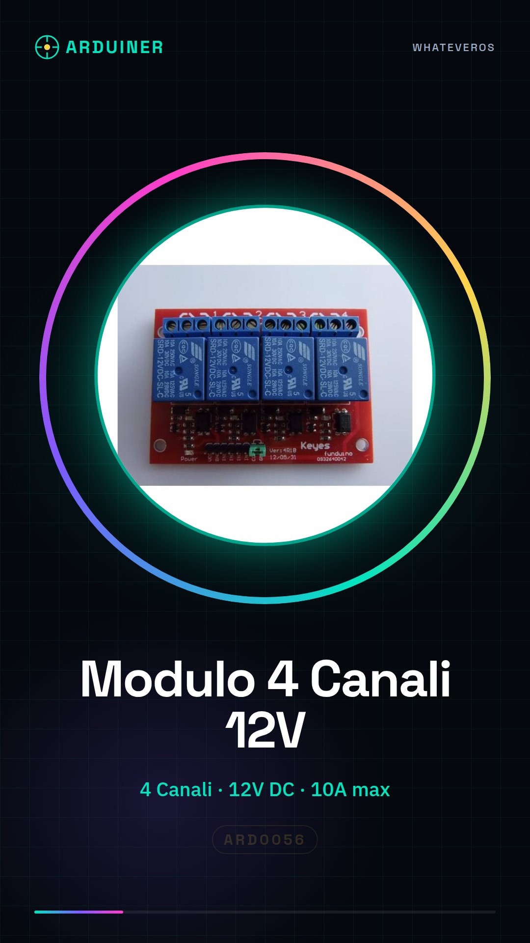
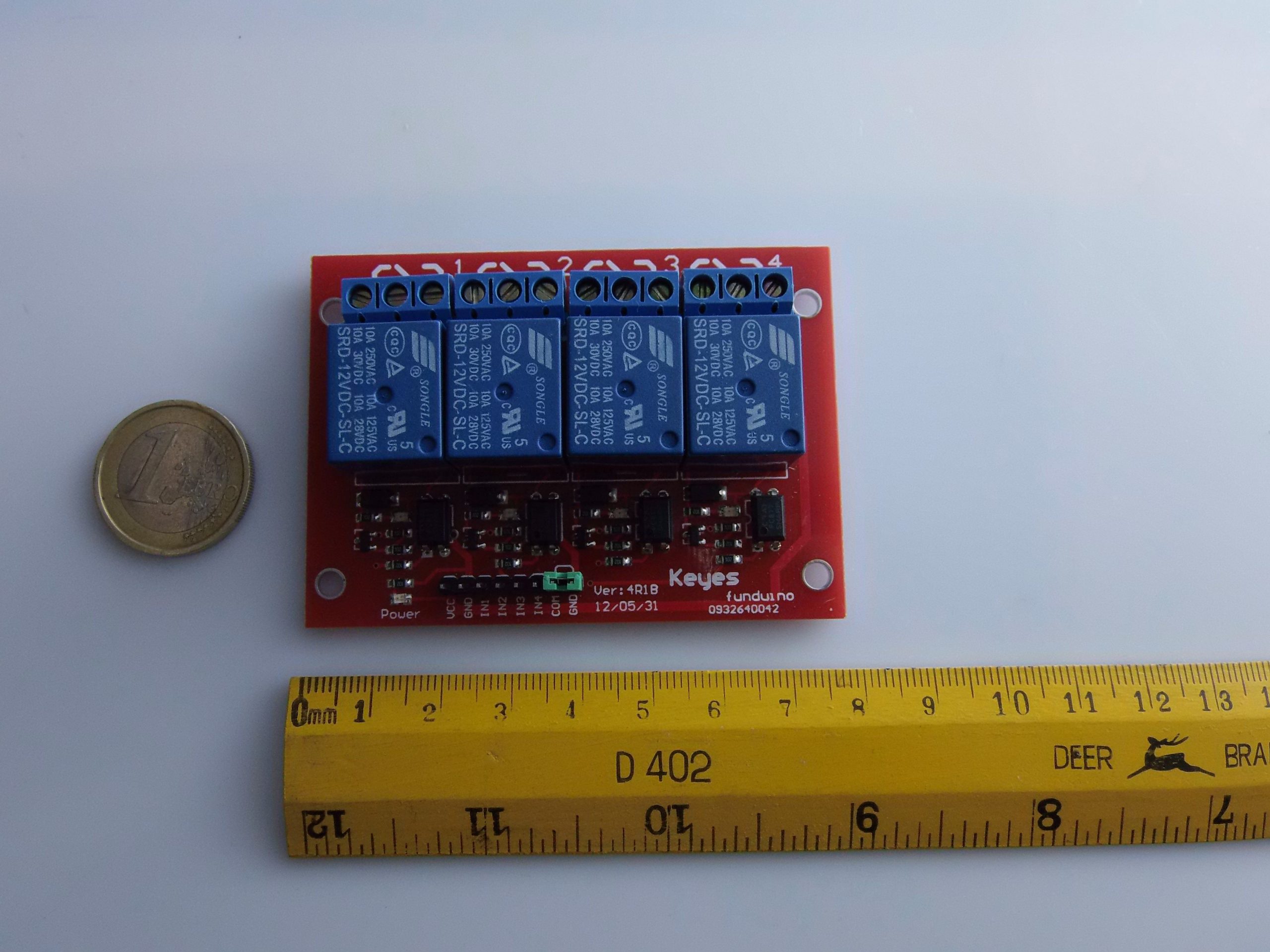
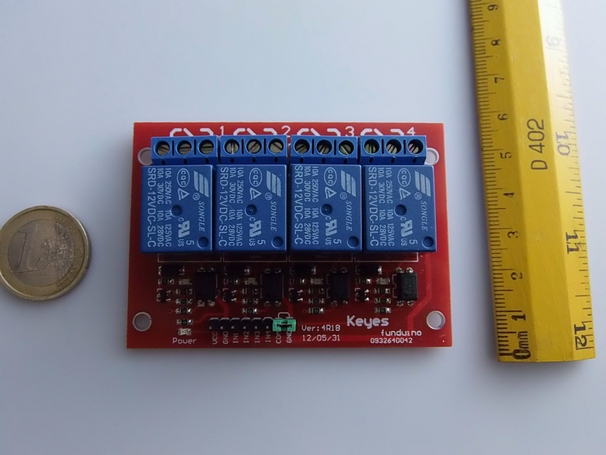
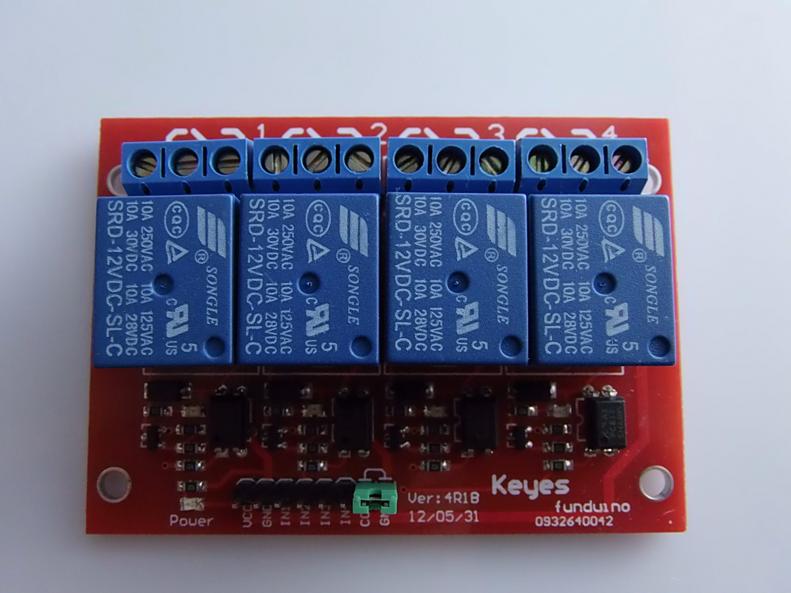
Description
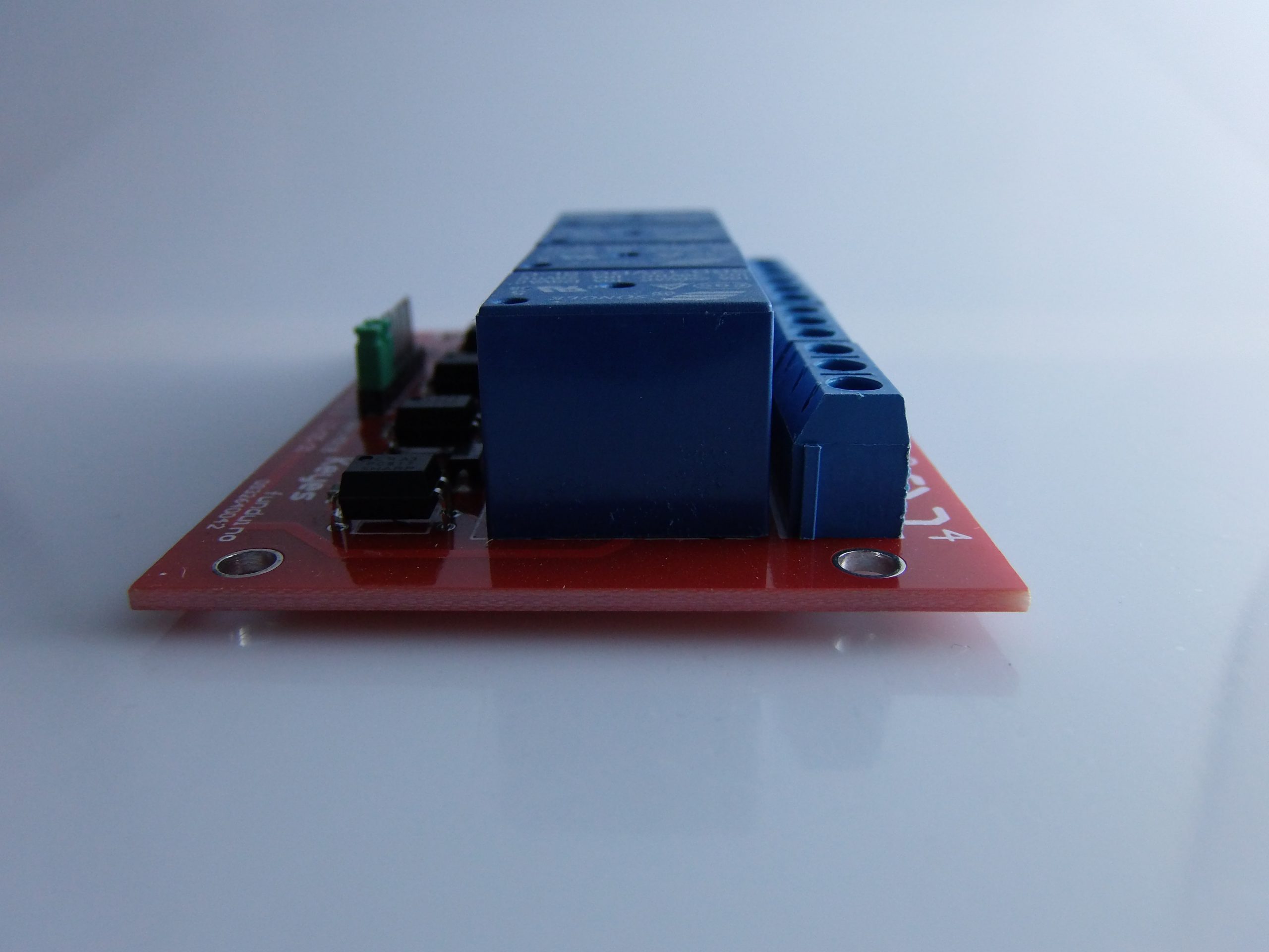
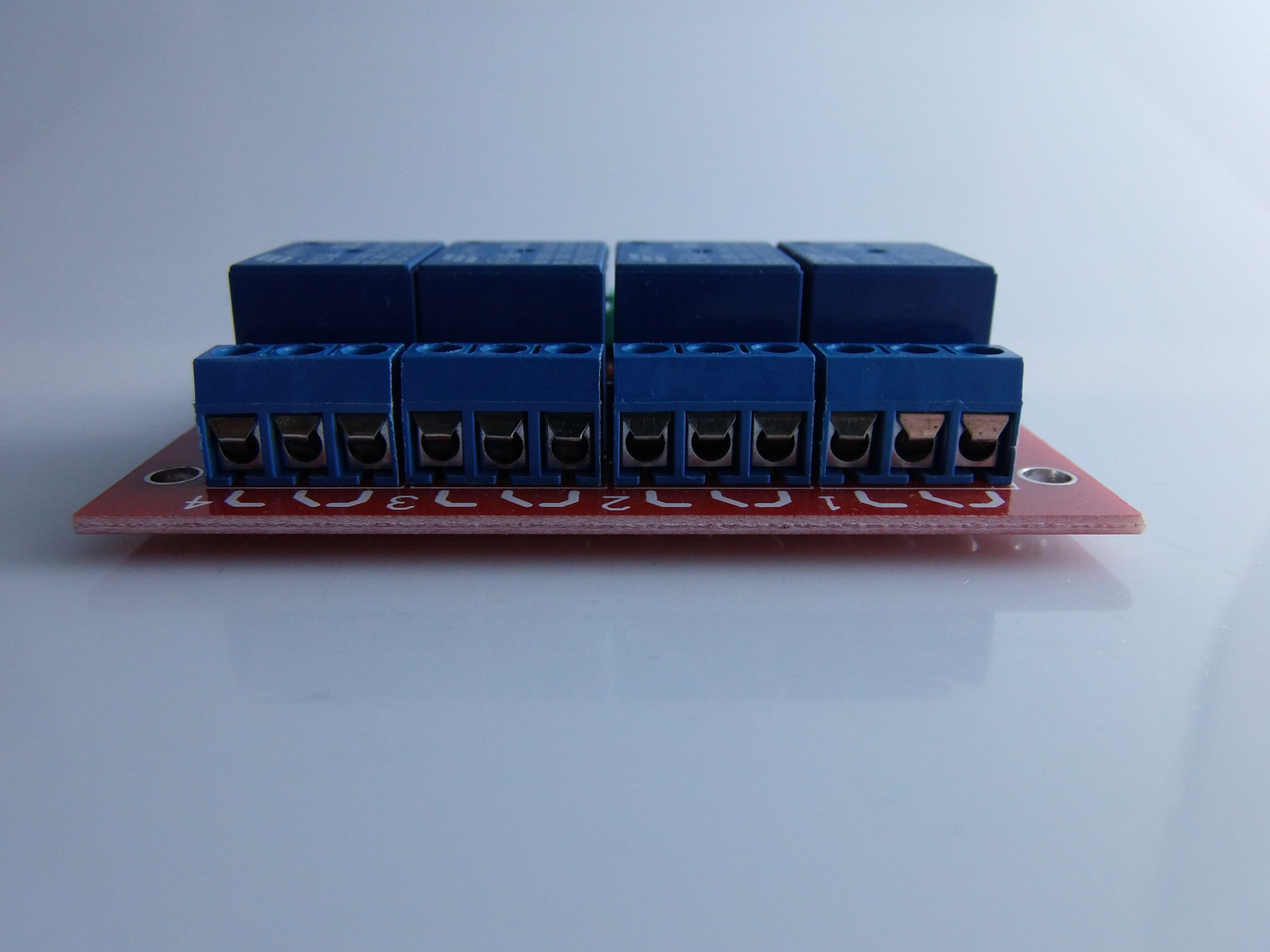
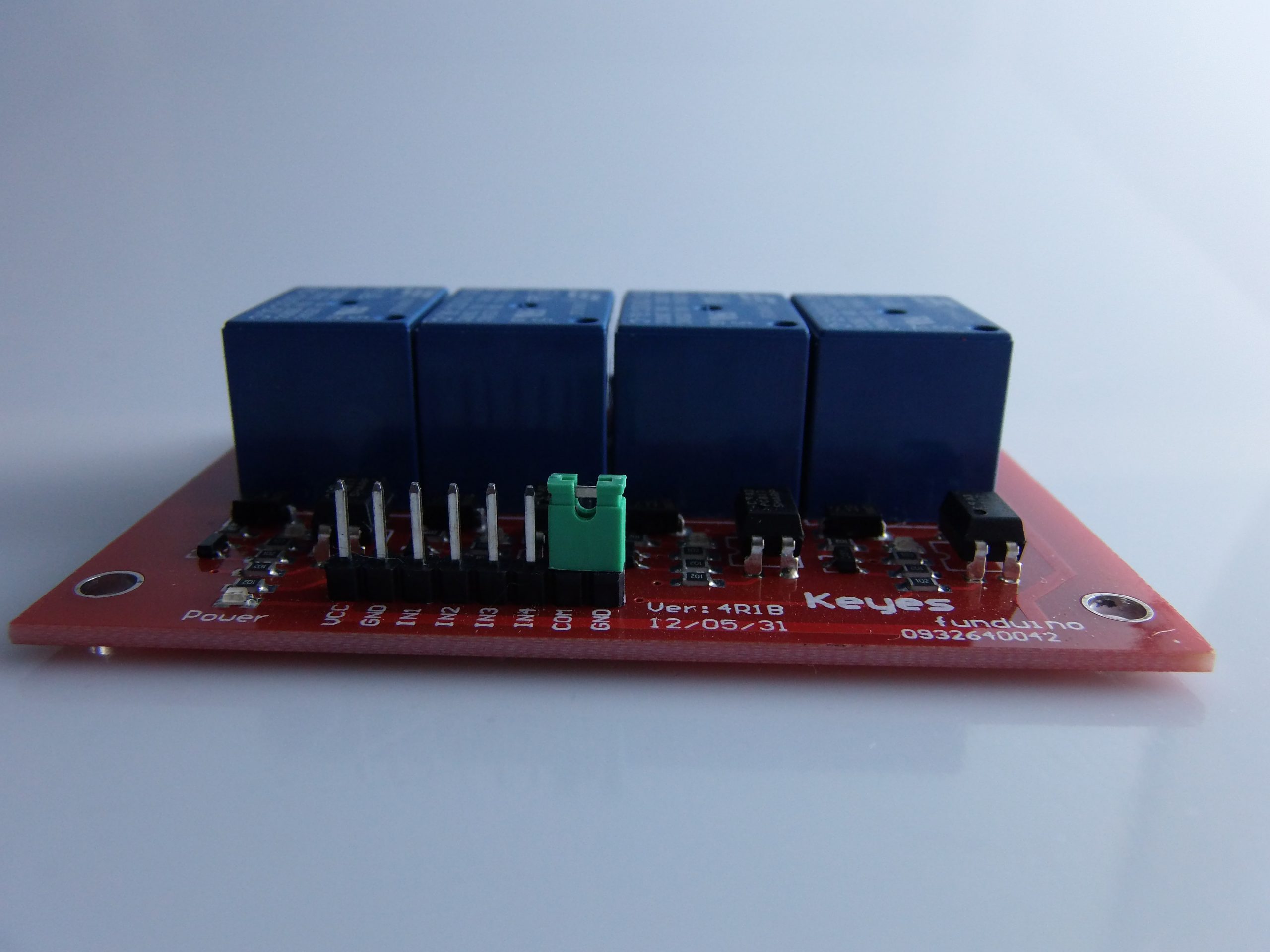
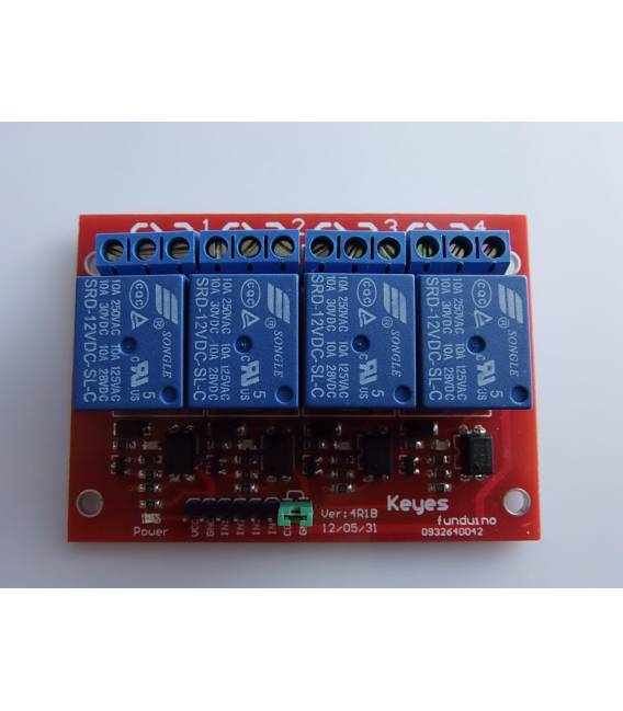
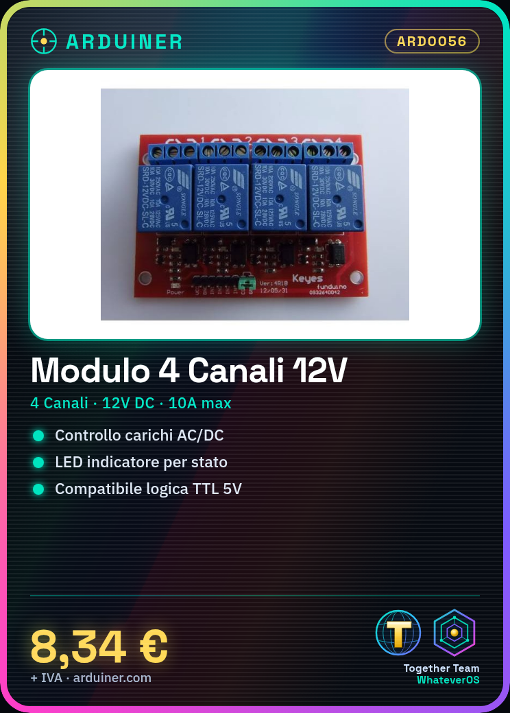
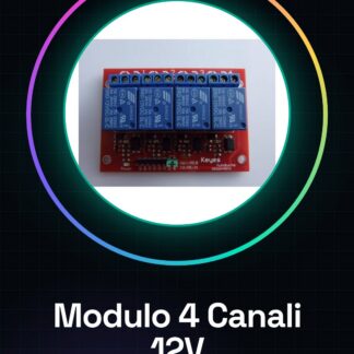
Here is a complete description of the 4 Channel 12V Relay Module for Arduino, PIC, ARM, AVR, DSP, followed by a detailed guide on how to use it with Arduino, with practical examples and code.
🔧 4 Channel 12V Relay Module – Technical Description
The 4 Channel 12V Relay Module is an electronic interface that allows the control of high-power or high-voltage loads (AC or DC) through low-power signals from microcontrollers such as Arduino, PIC, ARM, AVR, DSP.
✅ Main Features
- Number of Channels: 4 (independent)
- Operating Voltage: 12V DC
- Current Consumption: ~70-80 mA for each activated relay
- Relay Type: mechanical SPDT (Single Pole Double Throw) relay
- Maximum Current Supported by Relay: up to 10A at 250V AC or 10A at 30V DC
- Control Logic: TTL (compatible with 5V Arduino)
- Optoisolators: present (electrical protection between logic and load)
- LED Indicators: one for each channel to indicate the relay status
- Relay Contacts: NO (normally open), NC (normally closed), COM (common)
- Digital Inputs: IN1, IN2, IN3, IN4
🧰 Module Connections
| Relay Module Pin | Function | Arduino Connection |
|---|---|---|
| IN1 | Relay 1 Control | Digital Pin (e.g. D7) |
| IN2 | Relay 2 Control | Digital Pin (e.g. D6) |
| IN3 | Relay 3 Control | Digital Pin (e.g. D5) |
| IN4 | Relay 4 Control | Digital Pin (e.g. D4) |
| GND | Logic Ground | GND Arduino |
| VCC | Logic Power 5V | 5V Arduino |
| JD-VCC | 12V Relay Power Supply | 12V from external power supply |
⚠️ Attention: It is recommended to use a external power supply of 12V to power the relays. Do not power the relays directly from Arduino.
⚡ How to properly power the module
If the module has the jumper between VCC e JD-VCC, remove it if you are using a separate 12V power supply. In this way:
- JD-VCC → 12V external
- GND → GND Arduino and GND power supply
- VCC → 5V Arduino (logic control)
💻 Example Arduino Code
// Definizione dei pin collegati al modulo relè
const int rele1 = 7;
const int rele2 = 6;
const int rele3 = 5;
const int rele4 = 4;

void setup() {
 // Imposta i pin come output
 pinMode(rele1, OUTPUT);
 pinMode(rele2, OUTPUT);
 pinMode(rele3, OUTPUT);
 pinMode(rele4, OUTPUT);

 // Spegne tutti i relè all'avvio (dipende dalla logica del modulo)
 digitalWrite(rele1, HIGH);
 digitalWrite(rele2, HIGH);
 digitalWrite(rele3, HIGH);
 digitalWrite(rele4, HIGH);
}

void loop() {
 // Accende ogni relè uno alla volta
 digitalWrite(rele1, LOW); // Attiva relè 1
 delay(1000);
 digitalWrite(rele1, HIGH);

 digitalWrite(rele2, LOW); // Attiva relè 2
 delay(1000);
 digitalWrite(rele2, HIGH);

 digitalWrite(rele3, LOW); // Attiva relè 3
 delay(1000);
 digitalWrite(rele3, HIGH);

 digitalWrite(rele4, LOW); // Attiva relè 4
 delay(1000);
 digitalWrite(rele4, HIGH);
}
ℹ️ Note: Many relay modules activate with a LOW level (0V), so
digitalWrite(pin, LOW)activates the relay.
🧪 Practical Examples of Use
- Turning on a 230V AC light bulb
- Connect the light bulb to the network via the relay (live wire on COM and NO).
- When the relay is activated, it closes the circuit and the light bulb turns on.
- Control of a 12V DC pump
- 12V power → COM, pump → NO, common GND
- Arduino activates/deactivates the pump
- Automatic irrigation system
- Relay activates a 24V DC solenoid valve at scheduled times
📋 Good Practices and Safety
- DO NOT connect AC devices directly if you lack experience with mains current.
- Use relay with optoisolators to completely separate the Arduino logic from the high-voltage load.
- If you control inductive loads (motors, transformers), add flyback diodes o snubber.
- Always check theisolation between the logic and the relay contacts.
- Always use a external power supply for the relays if you are turning on more than one at the same time.
📘 Conclusion
The 4 Channel 12V Relay Module is an extremely useful tool for Arduino projects in home automation, industrial automation, irrigation, or remote control of electrical appliances. With proper power supply and control logic, you can easily integrate it into any project.
If you want, I can provide you with an electrical schematic or Fritzing diagram. Do you also want this?
|
GENERAL |
MODEL |
4 Channel 12V Relay Module |
|
MATERIALS |
pcb + components |
|
|
COMPATIBILITY |
ARDUINO |
|
|
ELECTRICAL COMPONENTS |
INPUT VOLTAGE |
12 V |
|
WEIGHT AND DIMENSIONS |
PRODUCT WEIGHT |
35g |
|
PACKAGE WEIGHT |
0.40 kg |
|
|
PRODUCT DIMENSIONS (L x P x A) |
8 x 6 x 4 cm | |
|
PACKAGE DIMENSIONS (L x W x H) |
10 x 15 x 5 cm |
|
|
PACKAGE CONTENT |
PACKAGE CONTENT |
1 x Module |
We have available the technical sheet of all components, if it is not present in the product download card, send us a message from the contact us form and we will publish as soon as possible on our website.
Tutorial: How to Use a 4-Channel Relay Module
The 4-channel relay module is ideal for controlling electrical devices with Arduino. It’s perfect for beginners who want to start with home or industrial automation projects.
What you need
- Arduino Uno
- USB Cable
- External Power Supply 12V
- Connecting to Electrical Devices
Steps
- Connect the relay module to the Arduino using the header connectors.
- Check the voltage of the device to be controlled (it must be 12V or less).
- Configure the external power supply for the relay module (12V) and plug it into the DC jack.
- Write the Arduino code to manage the relay channels.
- Upload the sketch to your Arduino.
- Check the correct activation of the relays through the Arduino IDE.
- Test each individual channel of the module.
- Verify that all connected devices respond correctly.
Example code
const int relayPin1 = 2; // definisci il pin per ogni canale
const int relayPin2 = 3;
const int relayPin3 = 4;
const int relayPin4 = 5;
void setup() {
pinMode(relayPin1, OUTPUT);
pinMode(relayPin2, OUTPUT);
pinMode(relayPin3, OUTPUT);
pinMode(relayPin4, OUTPUT);
digitalWrite(relayPin1, HIGH); // disattiva i relè
}
void loop() {
digitalWrite(relayPin1, LOW); // attiva il canale 1
delay(2000);
digitalWrite(relayPin1, HIGH);
delay(2000);
}
Mini project
Create an automatic lighting system that turns lights on and off based on a predefined sequence.
Common mistakes
- Do not check the device voltage before installation.
- Connect a device directly to pin 0 or 1 for relays without disabling the serial monitor.
- Omit the external power supply required for the relay module.
- Connect an electrical device directly to an Arduino pin without protection.
Recommended accessories
- USB Power Supply
- Wall Socket 12V
- Relay Shield for Arduino
- Motion Sensors
Frequently asked questions
Can the module handle multiple voltages?
Check the specific relay datasheet for voltage management.
Can I use this module with a Raspberry Pi?
Yes, but you need to add software and hardware protection for the GPIO pins.
Reviews
There are no reviews yet.