 EN
 IT Italiano
 ES Español
 FR Français
 DE Deutsch
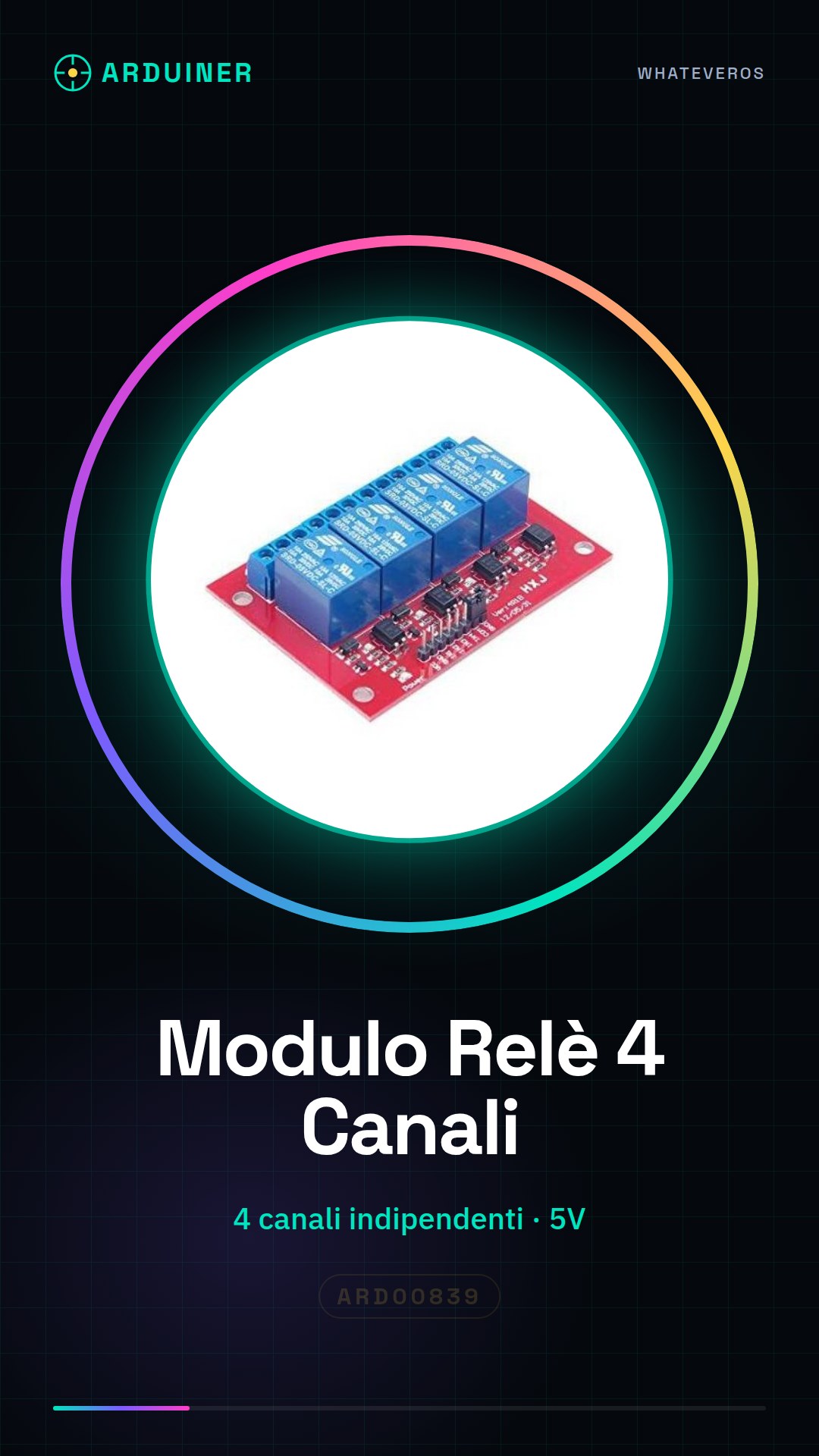
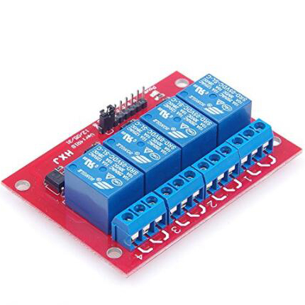
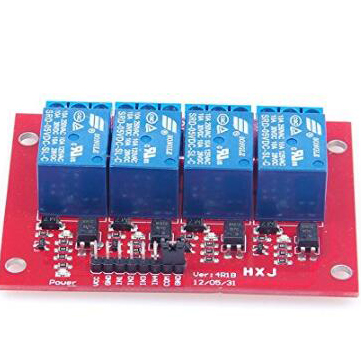
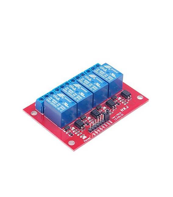
Description
Technical Description
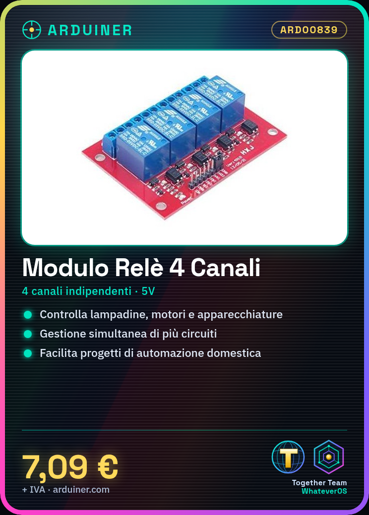
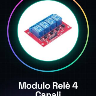
The 4-channel relay module is a crucial component for controlling electrical devices from microcontrollers like Arduino. It allows the management of up to four independent circuits, providing an isolation solution between the control circuit and the electrical circuit. Each relay can be activated or deactivated via a digital signal, enabling the regulation of power to devices such as lamps, motors, and other electrical appliances.
The module is designed to be easily integrated into home or industrial automation projects, offering a reliable and safe control solution. It is important to verify that the power supply voltage conforms to the module specifications to ensure optimal operation and prevent damage to the component.
The 4-channel relay module is suitable for projects that require the simultaneous control of multiple electrical devices, such as automatic lighting systems, door and window automation, or any other system that needs remote electrical control.
Key Specifications
| Parameter | Value |
| Model | 4 Channel 5V Relay Module |
| Number of Channels | 4 |
| Supply Voltage | 5V |
| Data Interface | Digital Pin |
| Dimensions | N/D (see manufacturer’s datasheet) |
| Enclosure | N/D (see manufacturer’s datasheet) |
Installation and Usage
- Connect the VCC and GND pins of the relay module to the corresponding power pins of the Arduino.
- Connect the data interface of the relay module to a digital pin of the Arduino (for example pin 7).
- Ensure that the supply voltage is in accordance with the module specifications.
- Write a simple sketch to test the functionality of the channels.
- Connect electrical devices to the 4 relays through the COM and NO/NC connectors.
Compatibility and Requirements
- The 4-channel relay module is compatible with Arduino Uno/R3 and other microcontrollers.
- To use the module, a USB cable is required to connect Arduino to the PC.
- If testing the module with real devices, an electrical network connection is necessary.
- The module can be integrated into projects that require the control of electrical devices from digital circuits.
Limitations and Important Notes
- The module does not include built-in protections for electrical devices.
- It is important to verify the compatibility of electrical devices with the relays before connecting them.
- The module does not provide electrical isolation between the control circuit and the electrical circuit.
- The operation of the module depends on the correct configuration of the microcontroller.
Troubleshooting
The relay does not activate.
Probable cause: The supply voltage does not conform to the module specifications.
Solution: Check the supply voltage and ensure it conforms to the module specifications.
The relay activates but does not deactivate.
Probable cause: The digital pin used to control the relay is not configured correctly.
Solution: Check the digital pin configuration in the Arduino code.
The relay activates but does not control the device.
Probable cause: The electrical device is not correctly connected to the relay connectors.
Solution: Check the connection of the electrical device to the relay connectors.
The relay activates but does not remain active.
Probable cause: The Arduino code does not maintain the digital signal high.
Solution: Check the Arduino code and ensure that the digital signal remains high for the required duration.
Use cases
Automatic lighting system.
Objective: Regulate the turning on and off of light bulbs.
What’s needed: Arduino Uno/R3, light sensors, USB cable.
Steps: 1) Connect the light sensors to Arduino. 2) Connect the relay module to Arduino. 3) Write a sketch to regulate the turning on and off of light bulbs. 4) Test the automatic lighting system.
Expected result: The automatic lighting system regulates the turning on and off of light bulbs based on ambient light.
Automation of doors and windows.
Objective: Regulate the opening and closing of doors and windows.
What’s needed: Arduino Uno/R3, motion sensors, USB cable.
Steps: 1) Connect motion sensors to Arduino. 2) Connect relay module to Arduino. 3) Write a sketch to control the opening and closing of doors and windows. 4) Test the automation of doors and windows.
Expected result: The automation of doors and windows regulates the opening and closing based on detected movements.
Automatic irrigation system.
Objective: Regulate the opening and closing of valves.
What is needed: Arduino Uno/R3, humidity sensors, USB cable.
Steps: 1) Connect humidity sensors to Arduino. 2) Connect relay module to Arduino. 3) Write a sketch to control the opening and closing of valves. 4) Test the automatic irrigation system.
Expected result: The automatic irrigation system regulates the opening and closing of valves based on soil moisture.
Garage door automation.
Objective: Control garage door opening and closing.
What’s needed: Arduino Uno/R3, motion sensors, USB cable.
Steps: 1) Connect motion sensors to Arduino. 2) Connect relay module to Arduino. 3) Write a sketch to control garage door opening and closing. 4) Test garage door automation.
Expected result: The garage door automation controls opening and closing based on detected movements.
Security lights automation.
Objective: Control the turning on and off of security lights.
What’s needed: Arduino Uno/R3, motion sensors, USB cable.
Steps: 1) Connect motion sensors to Arduino. 2) Connect relay module to Arduino. 3) Write a sketch to control the turning on and off of security lights. 4) Test security lights automation.
Expected Result: The security light automation turns lights on and off based on detected movements.
Automated Entry Door Control.
Objective: Regulate the opening and closing of entry doors.
What’s needed: Arduino Uno/R3, motion sensors, USB cable.
Steps: 1) Connect the motion sensors to Arduino. 2) Connect the relay module to Arduino. 3) Write a sketch to regulate the opening and closing of entry doors. 4) Test the automated entry door control.
Expected Result: The automated entry door control regulates the opening and closing based on detected movements.
Automated Exit Door Control.
Objective: Regulate the opening and closing of exit doors.
What’s needed: Arduino Uno/R3, motion sensors, USB cable.
Steps: 1) Connect motion sensors to Arduino. 2) Connect relay module to Arduino. 3) Write a sketch to control the opening and closing of exit doors. 4) Test the exit door automation.
Expected result: The exit door automation controls the opening and closing based on detected movements.
Exit door automation.
Objective: Control the opening and closing of access doors.
What you need: Arduino Uno/R3, motion sensors, USB cable.
Steps: 1) Connect motion sensors to Arduino. 2) Connect relay module to Arduino. 3) Write a sketch to control the opening and closing of access doors. 4) Test the access door automation.
Expected result: The access door automation controls the opening and closing based on detected movements.
In the package
- 4 pieces of 4-channel relay module
Complete the project
- 3 Channel 3.3V 5V Relay Module with Photocoupler for PIC AVR DSP ARM: To integrate the relay module into home or industrial automation projects.
- 2 Channel 5V Relay with Optocoupler each channel supports high/low level: To connect light or motion sensors to Arduino.
- USB Relay Module with 2 channels and control switch
- 8 Channel 5V Relay with Optocoupler each channel supports high/low level
Technical FAQs
How do I verify the correct power supply of the relay module?
Check that the power supply voltage conforms to the module specifications.
Why doesn’t the relay activate?
Check the power supply voltage and the digital pin configuration in the Arduino code.
How can I control multiple channels simultaneously?
Configure Arduino to control multiple channels simultaneously using digital signals on different pins.
What electrical devices can I connect to the relay module?
Electrical devices such as light bulbs, motors, and other electrical appliances.
Tutorial: How to Use 4-Channel Relay Module
The 4-channel relay module is a fundamental component for controlling electrical devices from Arduino. Ideal for beginners who want to start with home or industrial automation projects. This module allows you to manage up to four independent circuits, enabling you to regulate the power supply of devices such as light bulbs, motors, and other electrical appliances.
What you need
- Arduino Uno/R3
- USB cable to connect Arduino to PC
- Connection to electrical network (only if testing the module with real devices)
Steps
- Connect the VCC, GND pins of the relay module to the corresponding power pins of Arduino.
- Connect the data interface of the relay module to digital pin 7 of Arduino (or any other digital pin).
- Check that the power supply voltage is in line with the module specifications (check on the datasheet).
- Write a simple sketch to test the functionality of the channels.
- Connect electrical devices to the 4 relays through the COM and NO/NC connectors.
- Test each relay individually, turning on and off lights or other connected devices.
- Verify that the module functions correctly without interruptions.
- Configure Arduino to control multiple channels simultaneously (optional).
Example code
void setup() {
  pinMode(7, OUTPUT);
}

void loop() {
  digitalWrite(7, HIGH); // Accende il relè
  delay(1000);
  digitalWrite(7, LOW); // Spegne il relè
  delay(1000);
}
Mini project
Create an automatic lighting system with Arduino and this relay module. Connect different light bulbs to the relay channels and use light sensors to regulate their on and off.
Common mistakes
- Do not check that the power supply voltage is correct.
- Connect the device to the electrical network without protection.
- Use an analog pin instead of a digital pin to control the relays.
- Don’t forget to add resistors between Arduino and the relay module if necessary (check the datasheet).
Recommended accessories
- 16×2 LCD Module to monitor the state of the relays
- Light sensors for automatic lighting regulation
- Relay Shield for Arduino to facilitate the connection of the relay module
- Electronic Protection Kit to protect electrical devices
Frequently asked questions
Can the module handle more than 4 channels?
No, this module is designed exclusively for 4 channels.
Can I use the module with other microcontrollers besides Arduino?
Yes, but make sure that the digital pins of your microcontroller are compatible with the module’s input specifications (check the datasheet).
What is the maximum power for each relay?
Check the maximum value in the specifications section of the datasheet.
Reviews
There are no reviews yet.