 EN
 IT Italiano
 ES Español
 FR Français
 DE Deutsch
Description
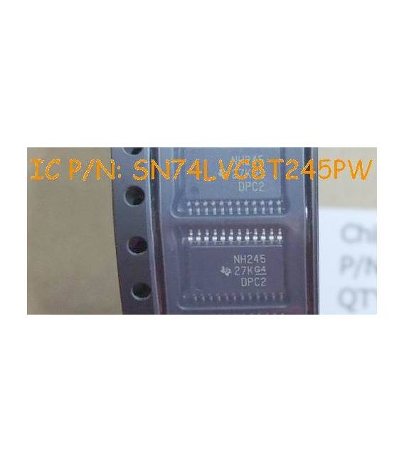
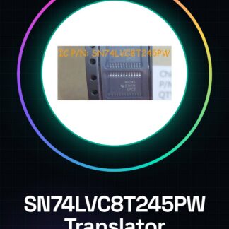
SN74LVC8T245PW Level Translator IC Integrated Circuits
Part Specifications:
| Logic Family | LVC |
| Operational Supply Voltage (Typical) | 1.8 / 2.5 / 3.3 / 5V |
| Propagation Delay Time | 32.2ns |
| Number of Elements | 1 |
| Number of Channels | 8 |
| Input Logic Level | LVTTL / TTL |
| Output Logic Level | LVCMOS |
| Output Type | 3-state |
| Package Type | TSSOP |
| Packaging | Rail / Tube |
| Polarity | Do not invert |
| Logic function | Bus transceiver with voltage translation |
| Operational supply voltage (min) | 1.65V |
| Operational supply voltage (max) | 5.5V |
| Technology | CMOS |
| Operational temperature range | from -40 ° C to 85 ° C |
| Operational temperature classification | Industrial |
| Mounting | Surface mounting |
| Additional functions | W / Volt Translation |
| Pin count | 24 |
We have the technical sheet for all components available, if it’s not present in the product download card, send us a message through the contact us form and we will publish it as soon as possible on our website.
Tutorial: How to use SN74LVC8T245PW Level Translator IC
The SN74LVC8T245PW is an integrated circuit used to translate voltage levels between two electronic devices. It is ideal for projects that require communication between components with different logic levels, such as Arduino and microcontrollers.
What you need
- SN74LVC8T245PW
- Arduino or other microcontroller
- 3.3V and 5V power supply connection
- Jumpers to connect the pins
Steps
- Check the operating voltage of your device and connect the appropriate voltage to VCCA and VCCB.
- Connect GND to common ground.
- Connect TXDA to the output signals of the first circuit, TXDB to the second circuit.
- Check the correct connection of the OE (Output Enable) pin to enable/disable the output.
- Connect the bidirectional signals (A<->B) to the signals you want to translate.
- Test the functionality with a simple Arduino code example.
Mini project
Create an interface between two microcontrollers with different logic levels. Connect TXDA to one and TXDB to the other, use OE to control the signal direction.
Common mistakes
- Do not check the supply voltages.
- Connect TXDA and TXDB incorrectly.
- Ignore the OE pin.
- Use an incompatible logic level with the IC.
Recommended accessories
- Jumpers to connect the pins
- Pull-up/pull-down resistors
- Arduino Uno or similar
- Prototype kit
Frequently asked questions
Can the SN74LVC8T245PW be used with Arduino?
Yes, it is perfect for translating signals between Arduino and other devices with different logic levels.
How can I control the signal direction?
Use the OE (Output Enable) pin to enable/disable the output in a specific direction.
Reviews
There are no reviews yet.