 EN
 IT Italiano
 ES Español
 FR Français
 DE Deutsch
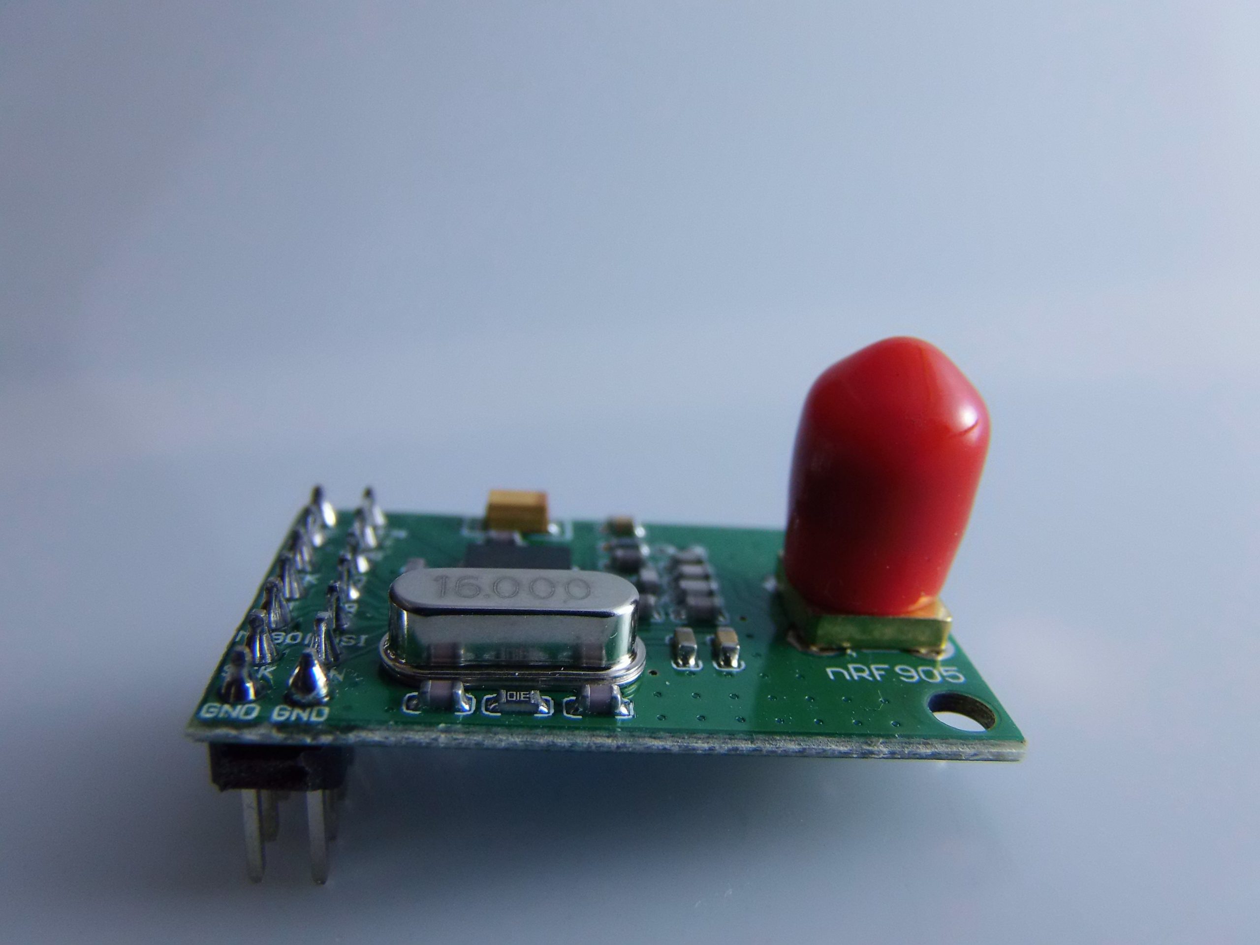
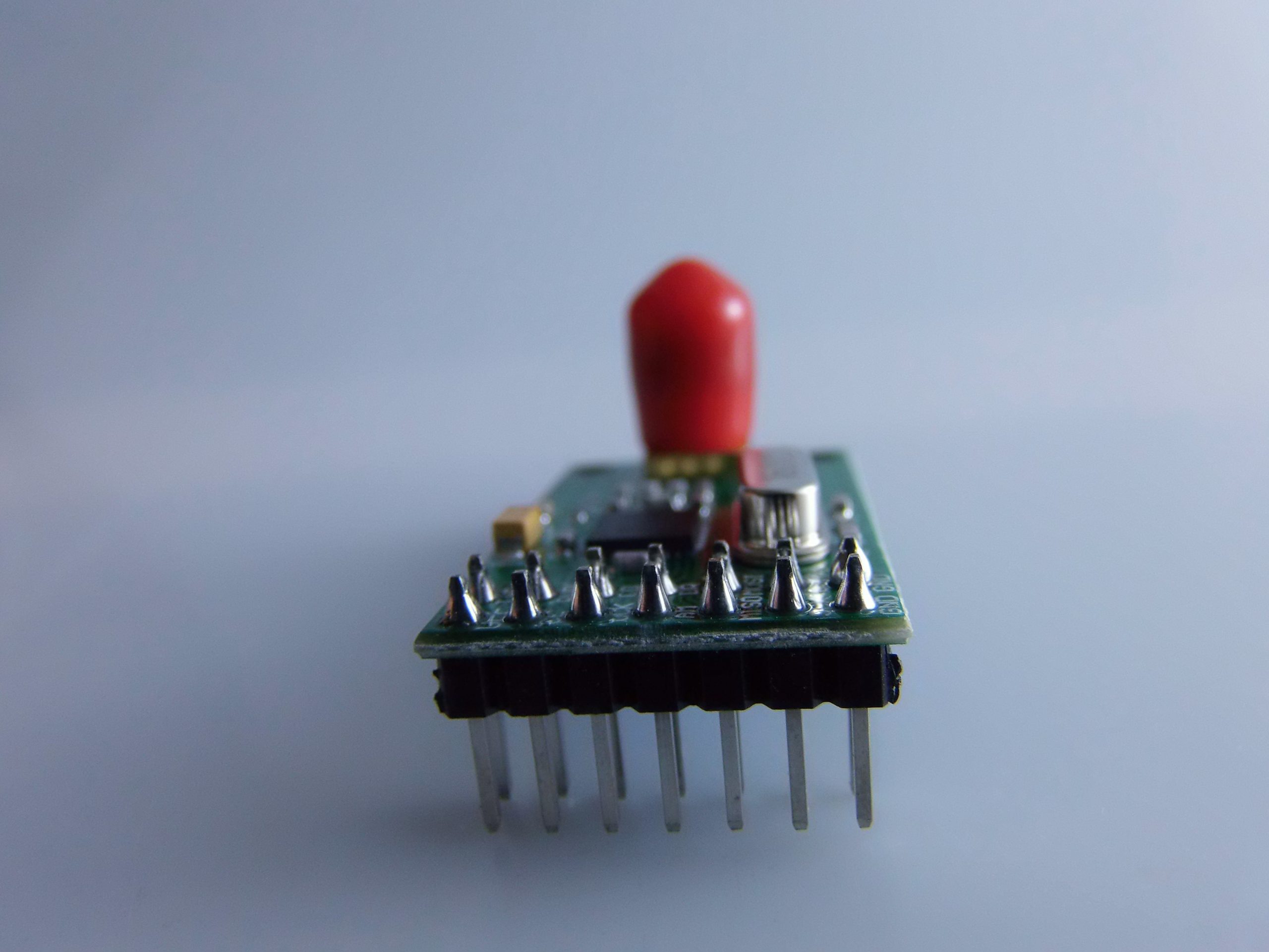
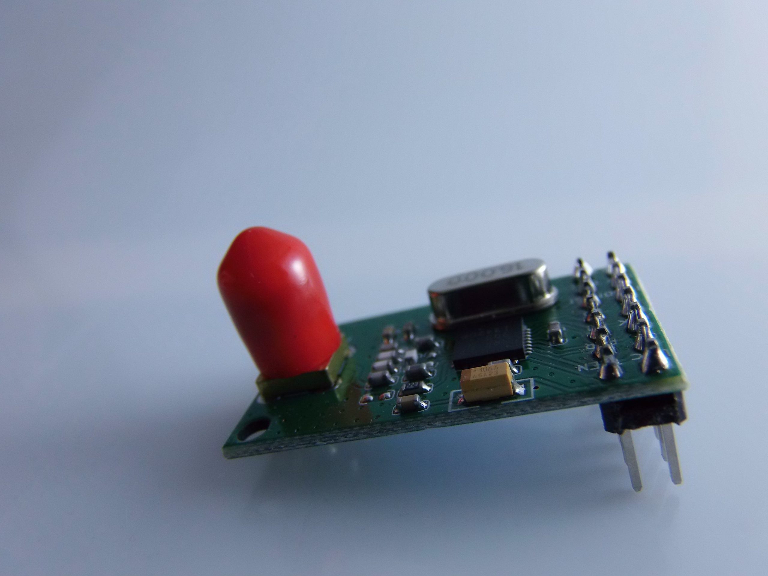
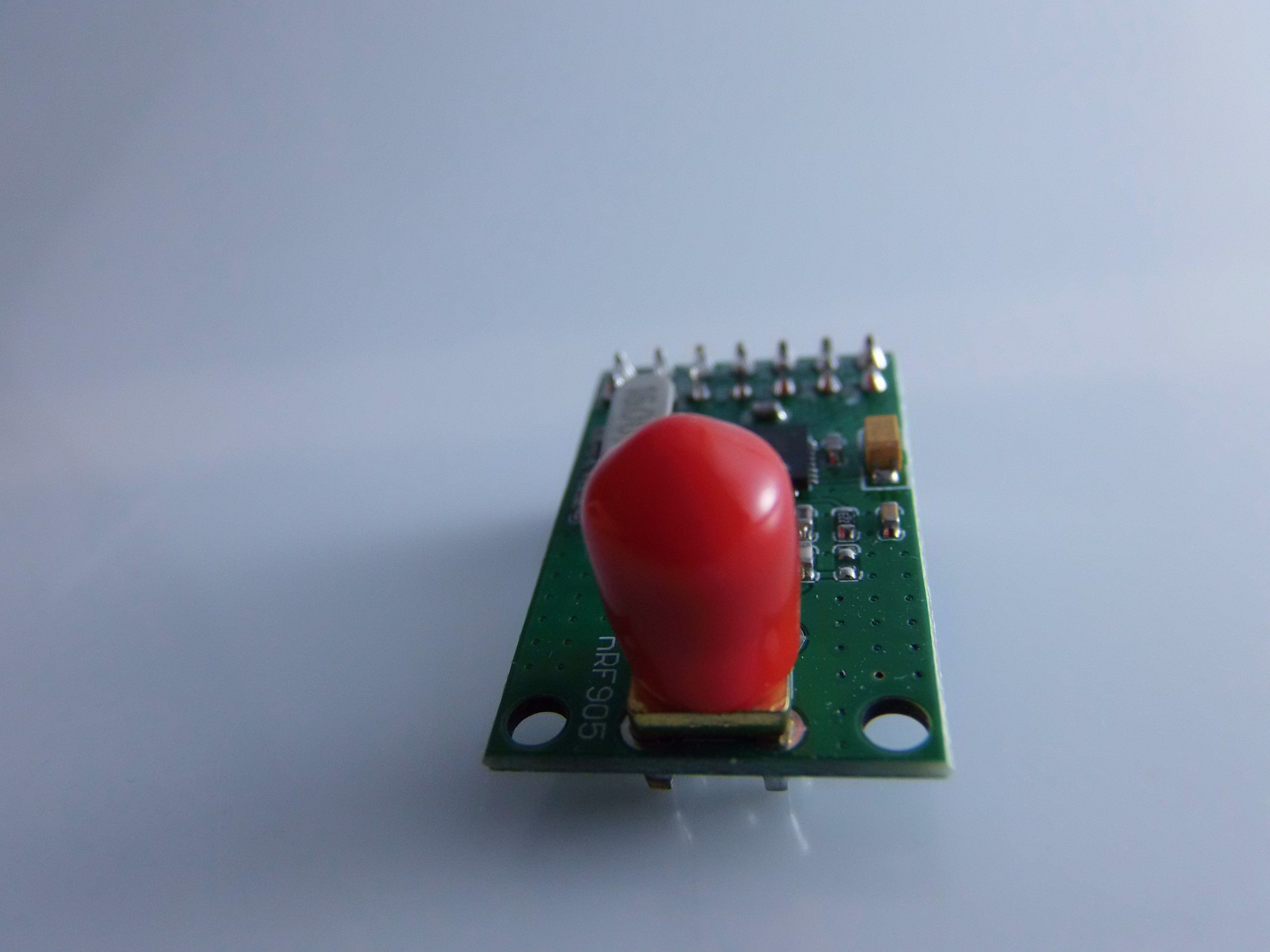
Description
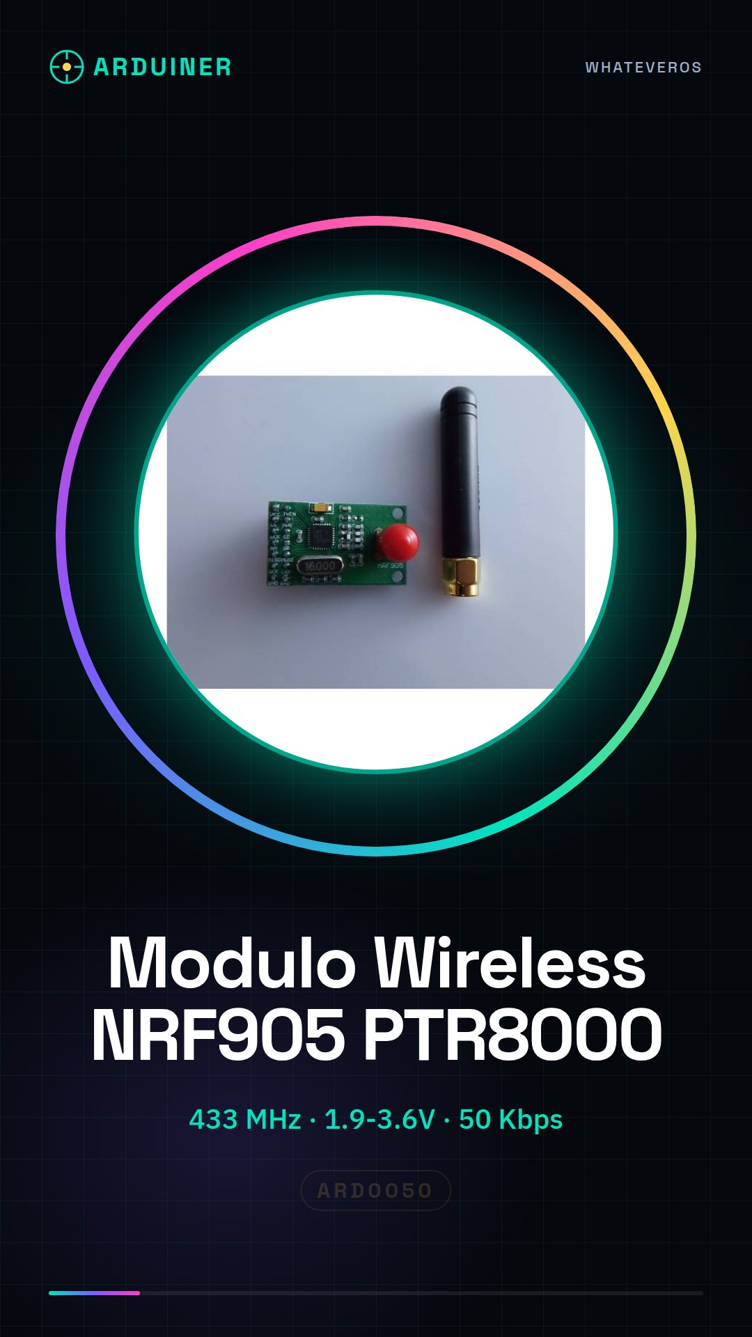
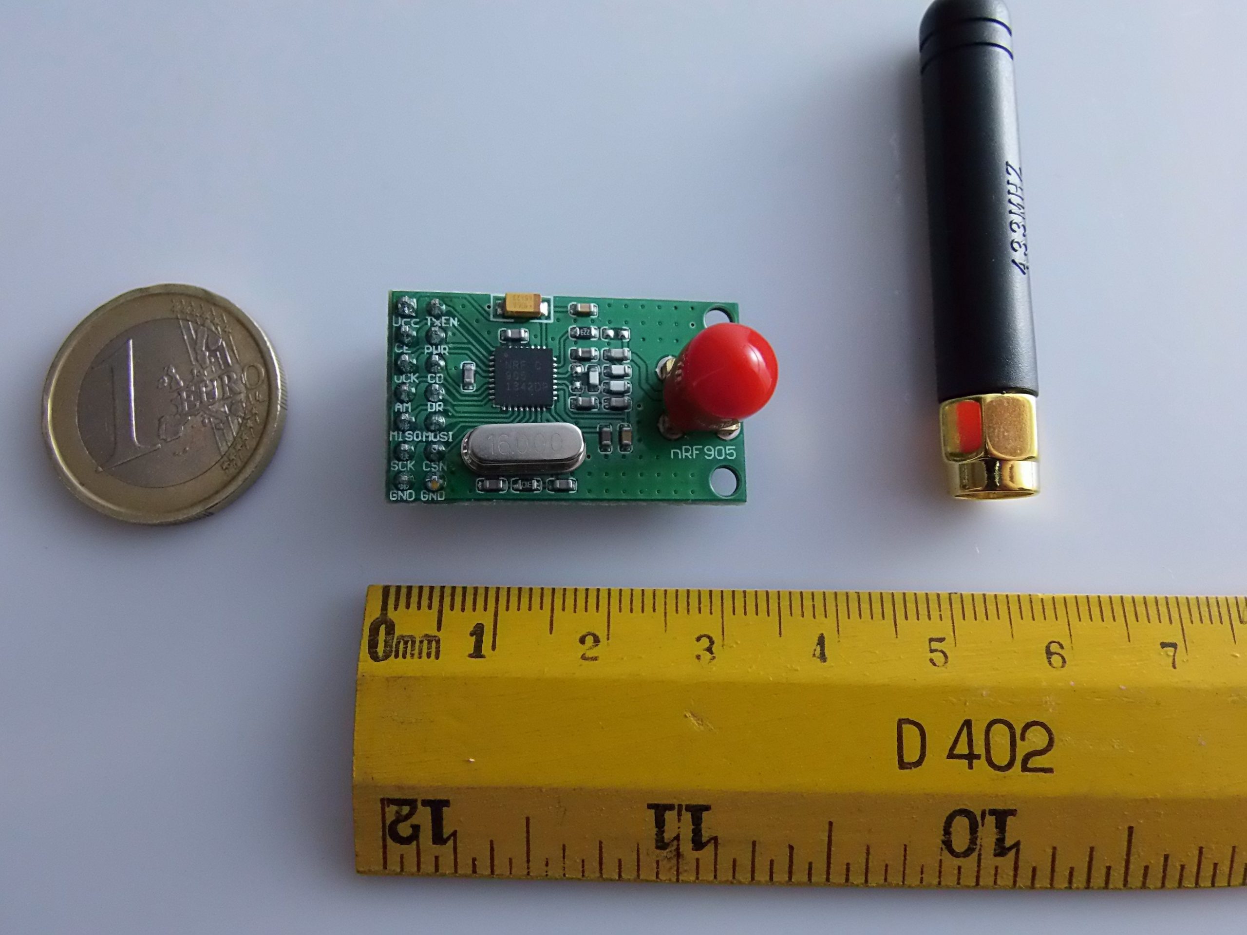
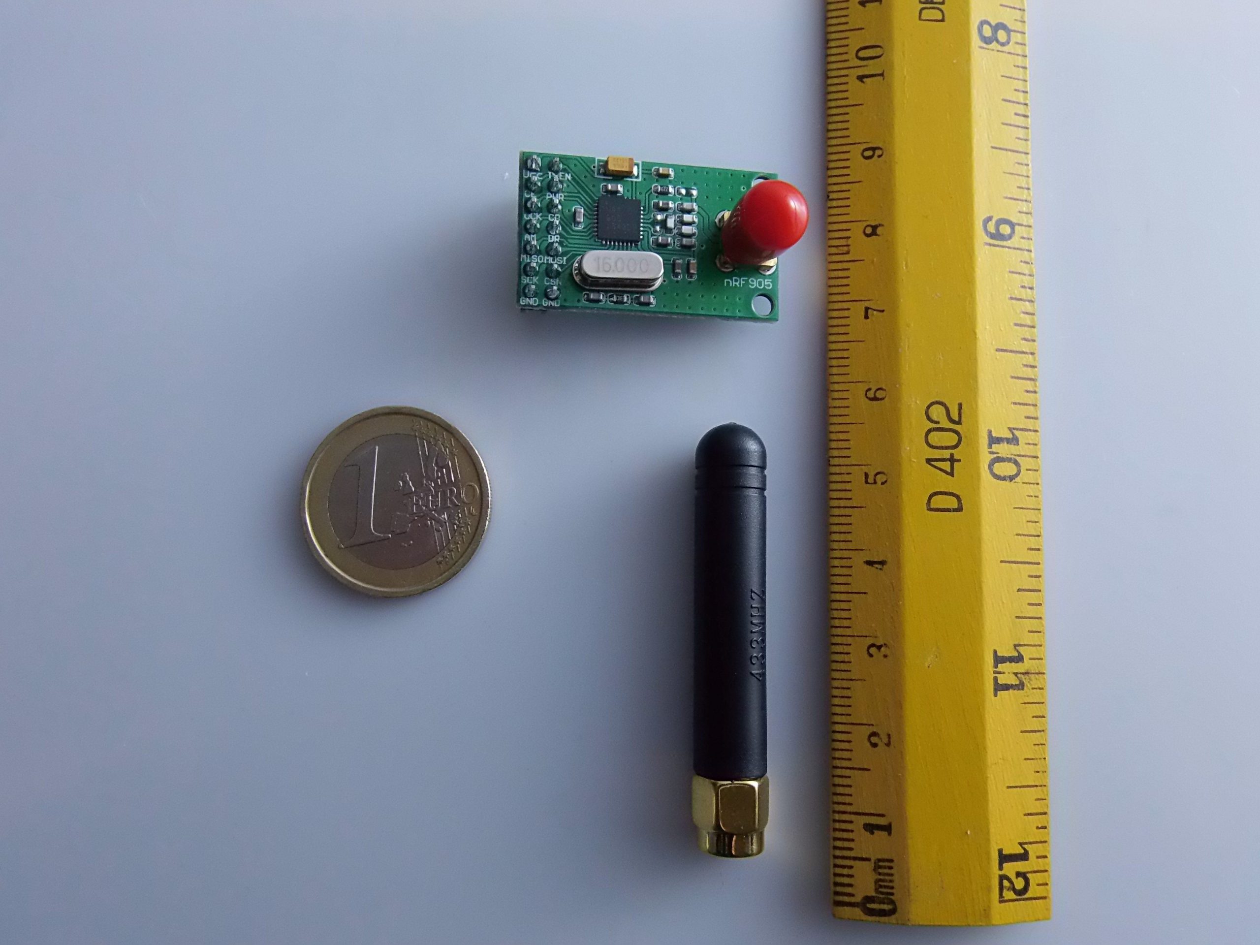
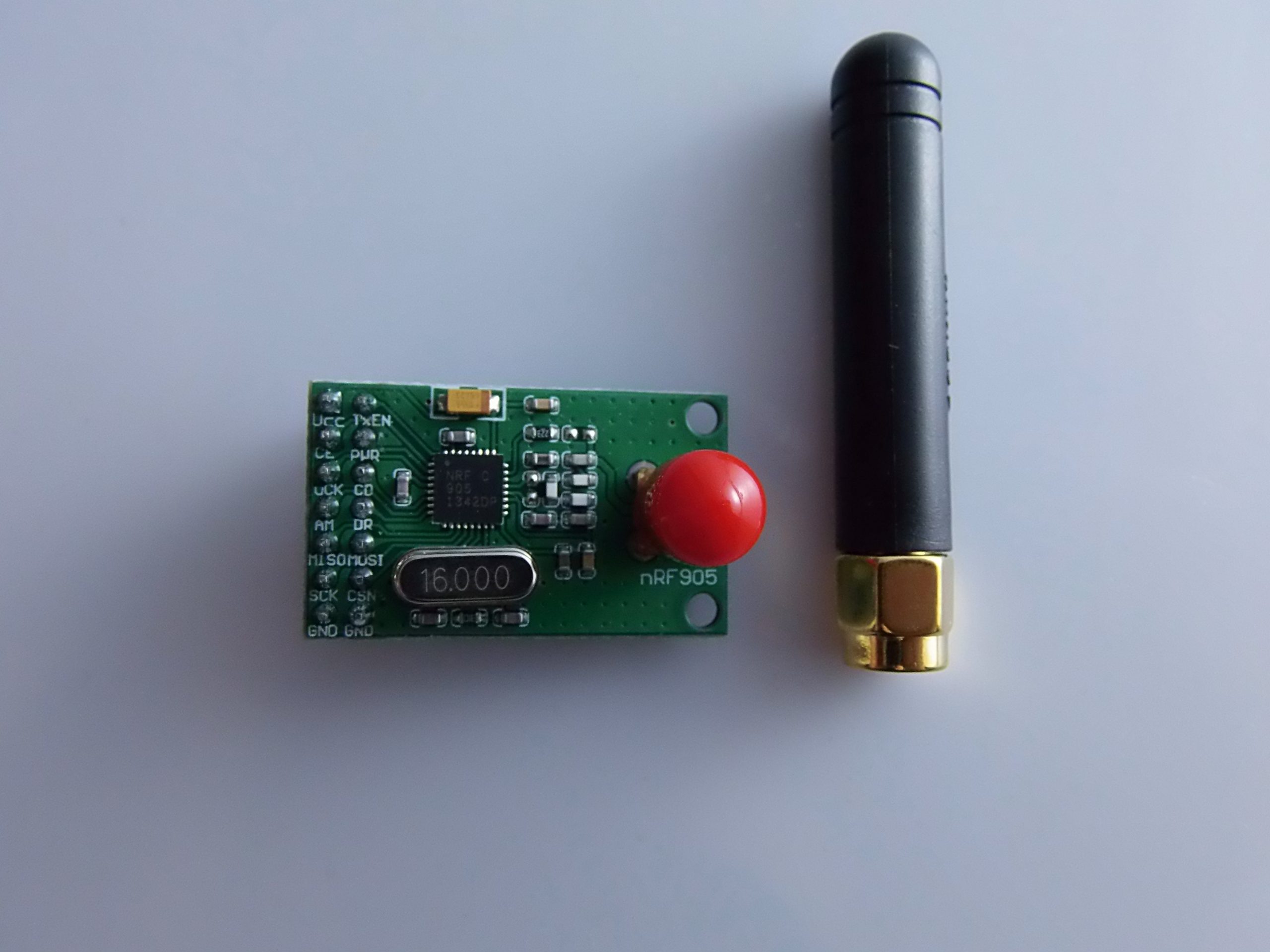
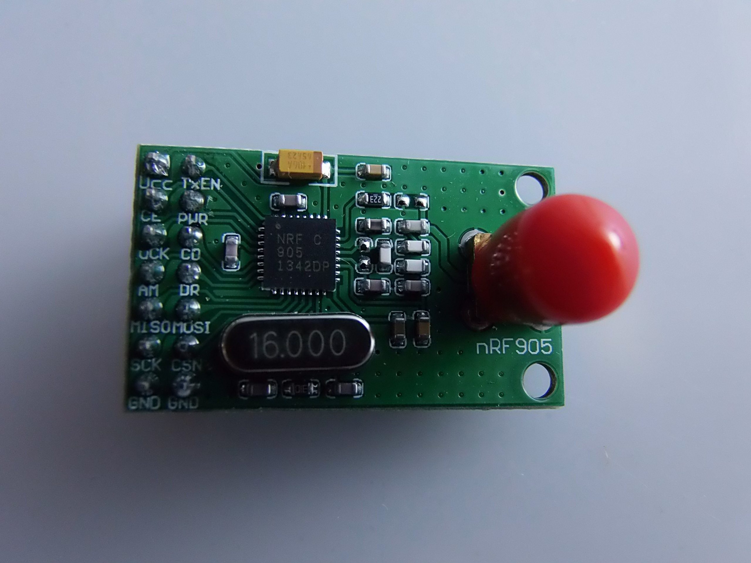
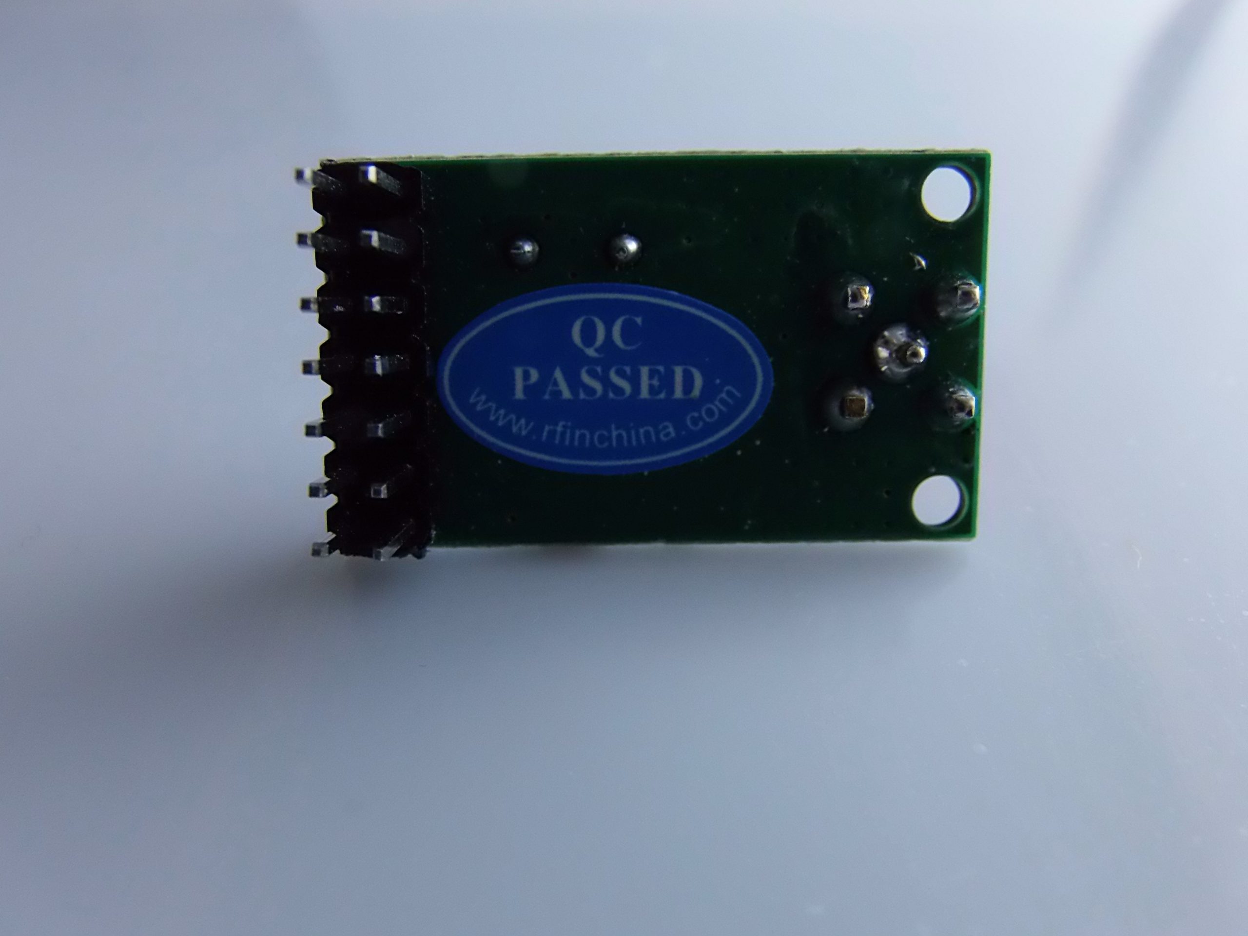
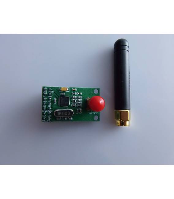
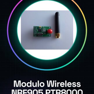
Here is a complete description of the module Wireless NRF905 PTR8000 433MHz with antenna, accompanied by a full guide for use with Arduino, including practical code examples.
🔧 Wireless NRF905 PTR8000 433MHz Module with antenna
📌 Main Features
- Model: NRF905 (PTR8000 version)
- Operating Frequency: 433 MHz (supports 868 MHz / 915 MHz via software selection)
- Modulation: GFSK (Gaussian Frequency Shift Keying)
- Operating Voltage: 1.9V – 3.6V (recommended 3.3V)
- Transmission Current: ~10 mA
- Reception Current: ~12.5 mA
- Range: up to 1000 meters in open field with appropriate antenna
- Transfer Speed: 50 Kbps
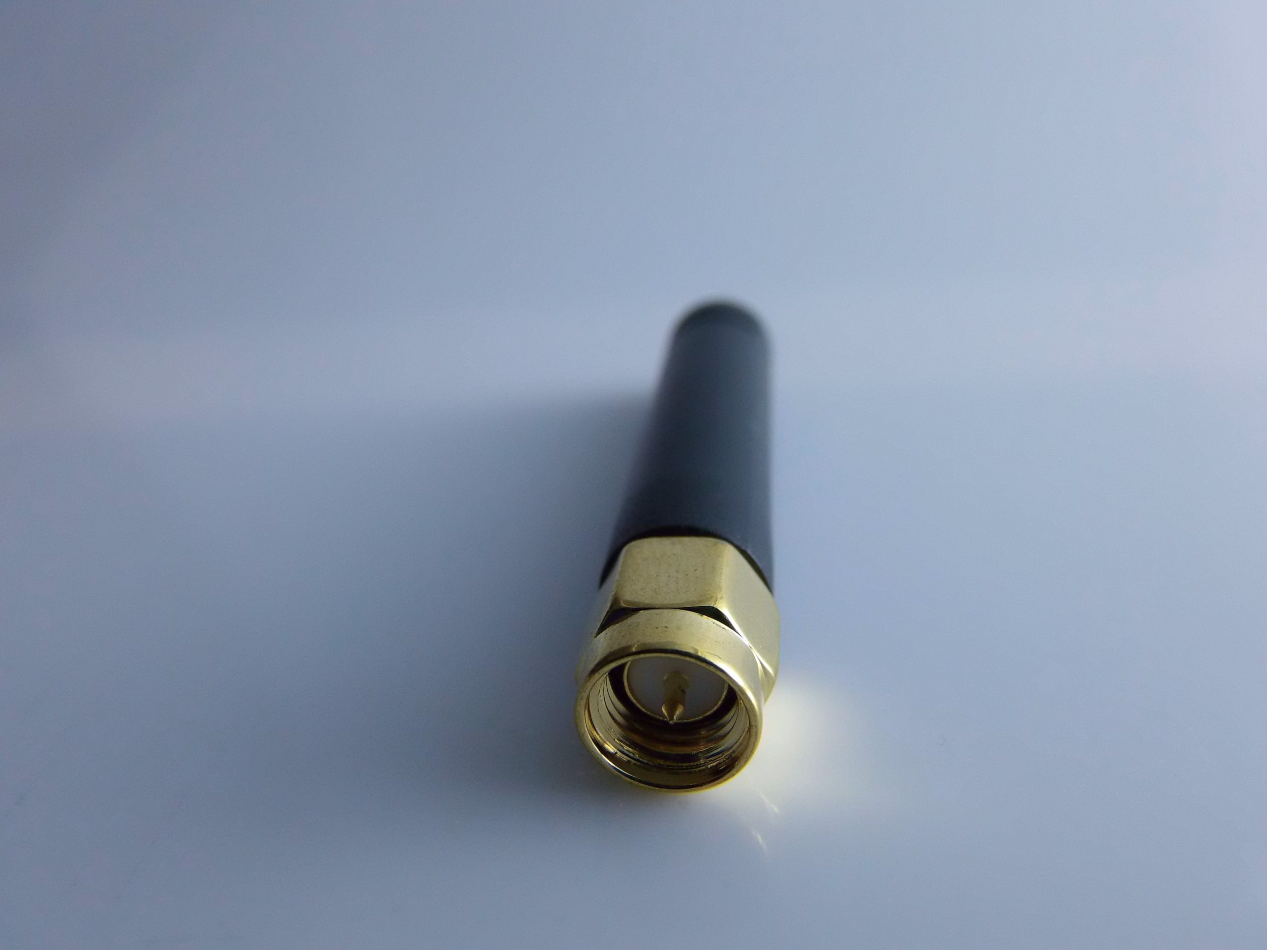
- Antenna: SMA 433/868/915 MHz included
- Interface: 4-wire SPI (MOSI, MISO, SCK, CSN)
- Compatibility: Arduino, ESP32, STM32, Raspberry Pi (via adapters)
📦 Module Pinout
| Pin | Description |
|---|---|
| VCC | 3.3V Power |
| GND | GND |
| MISO | SPI – Master In Slave Out |
| MOSI | SPI – Master Out Slave In |
| SCK | SPI – Clock |
| CSN (SEL) | Chip Select |
| CE | Chip Enable |
| TXE | Enable Transmission |
| PWR | Power Up Mode |
| DR | Data Ready |
| AM | Address Match |
| CD | Carrier Detect |
⚠️ Attention: Do not connect the module directly to 5V, it may get damaged. Use a logic level converter if working with 5V Arduino.
🧪 Configuration Guide with Arduino
✅ Required
- NRF905 PTR8000 Module
- Two Arduino UNO or similar (one transmitter, one receiver)
- Jumper wires
- 433 MHz SMA Antenna
- NRF905 Library
🔌 Connections with Arduino UNO
| NRF905 | Arduino UNO |
|---|---|
| VCC | 3.3V |
| GND | GND |
| MISO | 12 |
| MOSI | 11 |
| SCK | 13 |
| CSN | 10 |
| CE | 8 |
| TXE | 9 |
| PWR | 7 |
| DR | 2 (Optional Interrupt) |
🧰 Install the library
- Download the library from GitHub:
- Go to Arduino IDE > Sketch > Include Library > Add .ZIP Library and select the downloaded file.
📡 Example Code – Transmitter
#include <SPI.h>
#include <NRF905.h>

byte dataToSend[] = "HELLO";

void setup() {
 Serial.begin(9600);
 nrf905_init();
 Serial.println("Trasmettitore pronto.");
}

void loop() {
 nrf905_set_tx_data(dataToSend, sizeof(dataToSend));
 nrf905_tx();
 Serial.println("Dati trasmessi.");
 delay(1000);
}
📶 Example Code – Receiver
#include <SPI.h>
#include <NRF905.h>

void setup() {
 Serial.begin(9600);
 nrf905_init();
 Serial.println("Ricevitore pronto.");
}

void loop() {
 if (nrf905_data_ready()) {
 byte dataReceived[NRF905_MAX_PAYLOAD];
 nrf905_get_rx_data(dataReceived, NRF905_MAX_PAYLOAD);
 Serial.print("Ricevuto: ");
 for (byte i = 0; i < NRF905_MAX_PAYLOAD; i++) {
 Serial.write(dataReceived[i]);
 }
 Serial.println();
 }
}
⚙️ Advanced Configuration
You can modify:
- Frequency: via
nrf905_set_frequency(433000000); - Data Rate: only 50 Kbps (not modifiable)
- Transmission Power: function
nrf905_set_power(0); // da 0 a 3
📌 Usage Tips
- Use two modules for testing (one TX, one RX).
- Avoid interference: test in environments with few RF signals.
- Power the module with a stable 3.3V regulator.
- The library supports only buffers up to 32 bytes.
📚 Useful Resources
- Official NRF905 Datasheet: Nordic Semiconductor Datasheet
- Alternative library (more advanced): https://github.com/zkemble/nRF905
|
GENERAL |
MODEL |
NRF905 |
|
MATERIALS |
pcb + plastic + components |
|
|
COMPATIBILITY |
ARDUINO |
|
|
ELECTRICAL COMPONENTS |
INPUT VOLTAGE |
1.9 – 3.6 V |
|
WEIGHT AND DIMENSIONS |
PRODUCT WEIGHT |
11g |
|
PACKAGE WEIGHT |
0.155 kg |
|
|
PRODUCT DIMENSIONS (L x W x H) |
3.2 x 2 x 1.3 cm + 5 x 0.7 x 0.7 cm |
|
|
PACKAGE DIMENSIONS (L x W x H) |
5 x 10 x 2 cm |
|
|
CONTENTS OF THE PACKAGE |
CONTENTS OF THE PACKAGE |
1 x Module |
We have available the technical sheet of all components, should it not be present in the product download card send a message from the contact us form and we will publish as soon as possible on our website.
Tutorial: How to use NRF905
This wireless module is ideal for projects that require long-range wireless data transmission. Useful for beginners and intermediate makers.
What you need
- Arduino or compatible microcontroller
- Power cable
- Antenna (optional)
- 10kΩ resistor (for pull-up)
Steps
- 1. Connect the NRF905 module to the microcontroller using the following pins: VCC to 5V, GND to GND, TX to one of the RX pins of the microcontroller (e.g., pin 10 of Arduino).
- 2. Connect the antenna to the ANT pin of the module (optional).
- 3. Connect a 10kΩ resistor between the RX pin of the module and the GND pin. This resistor acts as a pull-up.
- 4. Load the following code onto the microcontroller.
- 5. Configure the transmission frequency (433MHz, 486MHz or 915MHz) on the module.
- 6. Test the transmission by sending a message.
- 7. Connect another NRF905 module to another microcontroller.
- 8. Configure the same frequency on the second module and receive the sent message.
Example code
```cpp
#include <SoftwareSerial.h>

SoftwareSerial nrf905(10, 11); // RX, TX

void setup() {
 nrf905.begin(433000); // Configura frequenza
 Serial.begin(9600);
}

void loop() {
 if (nrf905.available()) {
 String message = nrf905.readString();
 Serial.println(message);
 }
}
```
Mini project
Create a remote alarm system. Install an NRF905 module on a motion detector and the other on a doorbell. When the motion detector is triggered, the doorbell rings.
Common mistakes
- Fail to correctly configure the frequency on the module.
- Forget the pull-up resistor.
- Connect the module to the microcontroller with the wrong pins.
- Use a frequency not supported by the module.
Recommended accessories
- NRF905 Module 433MHz
- Arduino Uno
- 433/486/915MHz Antenna
- Motion Detector
Frequently asked questions
How can I check the supported frequency of the module?
Check the datasheet.
Can I use this module with a microcontroller different from Arduino?
Yes, but make sure the pinout is compatible.
Which pull-up resistor to use?
10kΩ.
Reviews
There are no reviews yet.