 EN
 IT Italiano
 ES Español
 FR Français
 DE Deutsch
Description
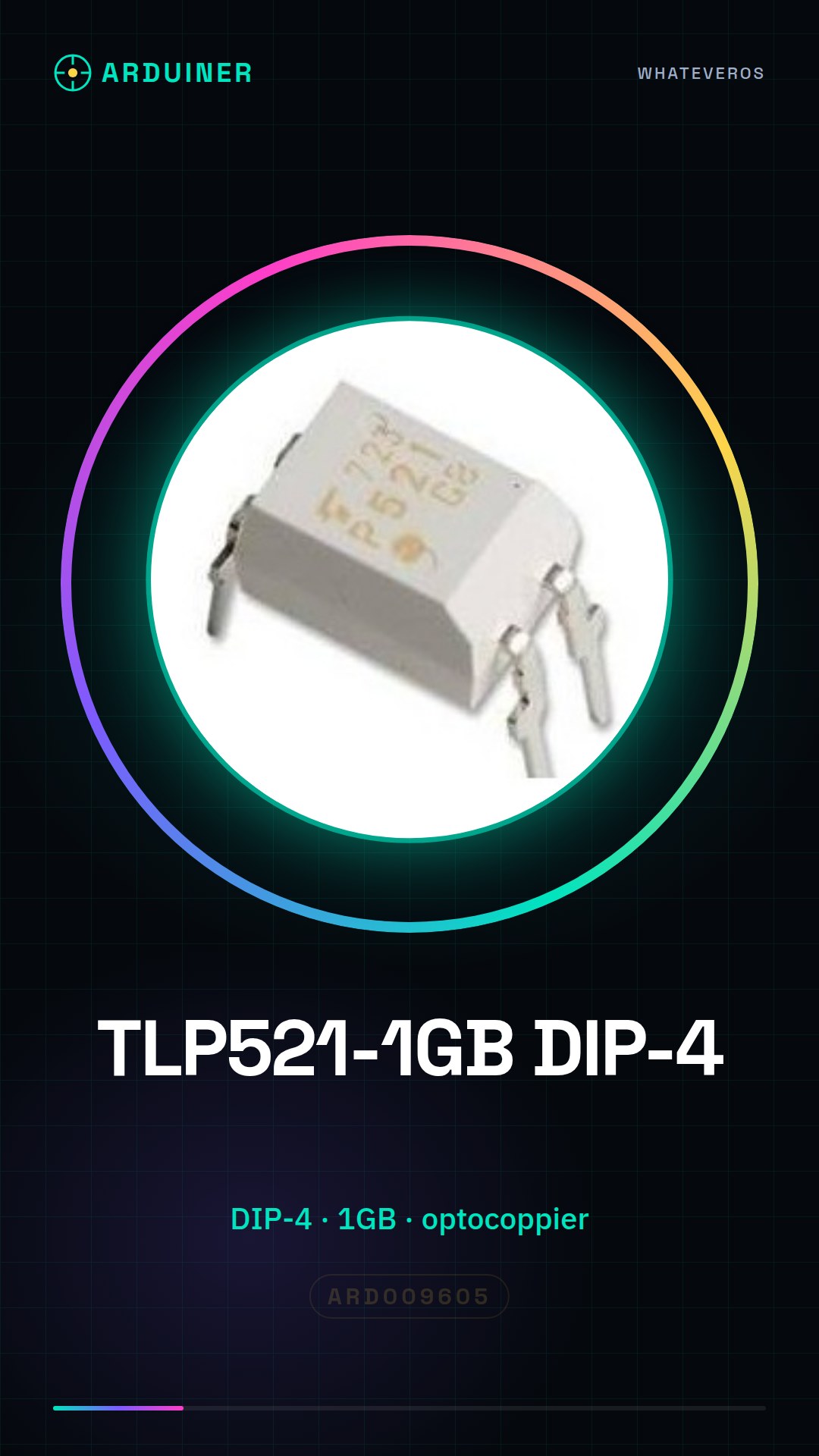
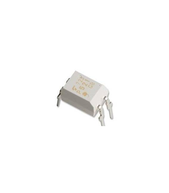
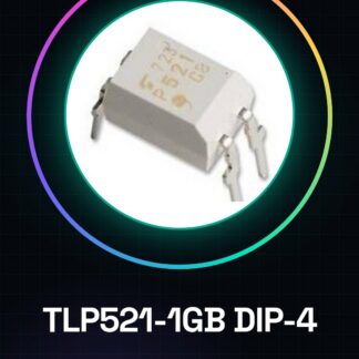
TLP521-1GB DIP-4
Tutorial: How to Use TLP521-1GB DIP-4
The TLP521-1GB DIP-4 is an optocoupler that allows electrical isolation between two circuits, ensuring safety and stability in operation. This component is ideal for projects such as remote controllers or protection systems.
What you need
- Arduino Uno
- TLP521-1GB DIP-4
- 330 Ohm Resistor
- Jumper Wire
Steps
- Step 1: Connect the 330 Ohm resistor between the output of the control pin of the Arduino and the internal LED of the optocoupler.
- Step 2: Connect the anode (pin 1) of the optocoupler to the control pin of the Arduino through the resistor.
- Step 3: Connect the cathode (pin 2) of the optocoupler to ground (GND).
- Step 4: Connect the output of the phototransistor (pin 4) to the input pin of the Arduino through a jumper wire.
- Step 5: Verify the correct installation of the electrical connections using a multimeter.
- Step 6: Write an Arduino sketch to control the optocoupler (see the ‘Code’ section).
- Step 7: Test the optocoupler’s functionality by turning the LED connected to the other side of the circuit on and off.
- Step 8: Verify that the output of the phototransistor changes state in response to commands sent from the Arduino.
Example code
const int ledPin = 13; // Pin di controllo dell'optocoppier
const int inputPin = 2; // Pin di input dal fototransistor
void setup() {
  pinMode(ledPin, OUTPUT);
pinMode(inputPin, INPUT_PULLUP);}
void loop() {
digitalWrite(ledPin, HIGH); delay(1000);
digitalWrite(ledPin, LOW); delay(1000);} // Alternanza del segnale
Mini project
Create an automatic protection system for power supplies that activates when a short circuit is detected.
Common mistakes
- Connect the phototransistor directly to a voltage without going through the optocoupler.
- Do not verify the correct resistance to protect the internal LED of the optocoupler.
- Try to use the optocoupler as a simple electronic relay, ignoring its isolating function.
- Ignore the polarity of the phototransistor during connections.
Recommended accessories
- Arduino Uno
- Variable resistors
- 3D printing for prototypes
- Motion sensors
Frequently asked questions
What is the correct value of the resistance?
Check the datasheet for the TLP521-1GB DIP-4.
Can I use the optocoupler without an Arduino?
Yes, but an alternative control circuit will be necessary.
Reviews
There are no reviews yet.