 EN
 IT Italiano
 ES Español
 FR Français
 DE Deutsch
Description
Technical Description
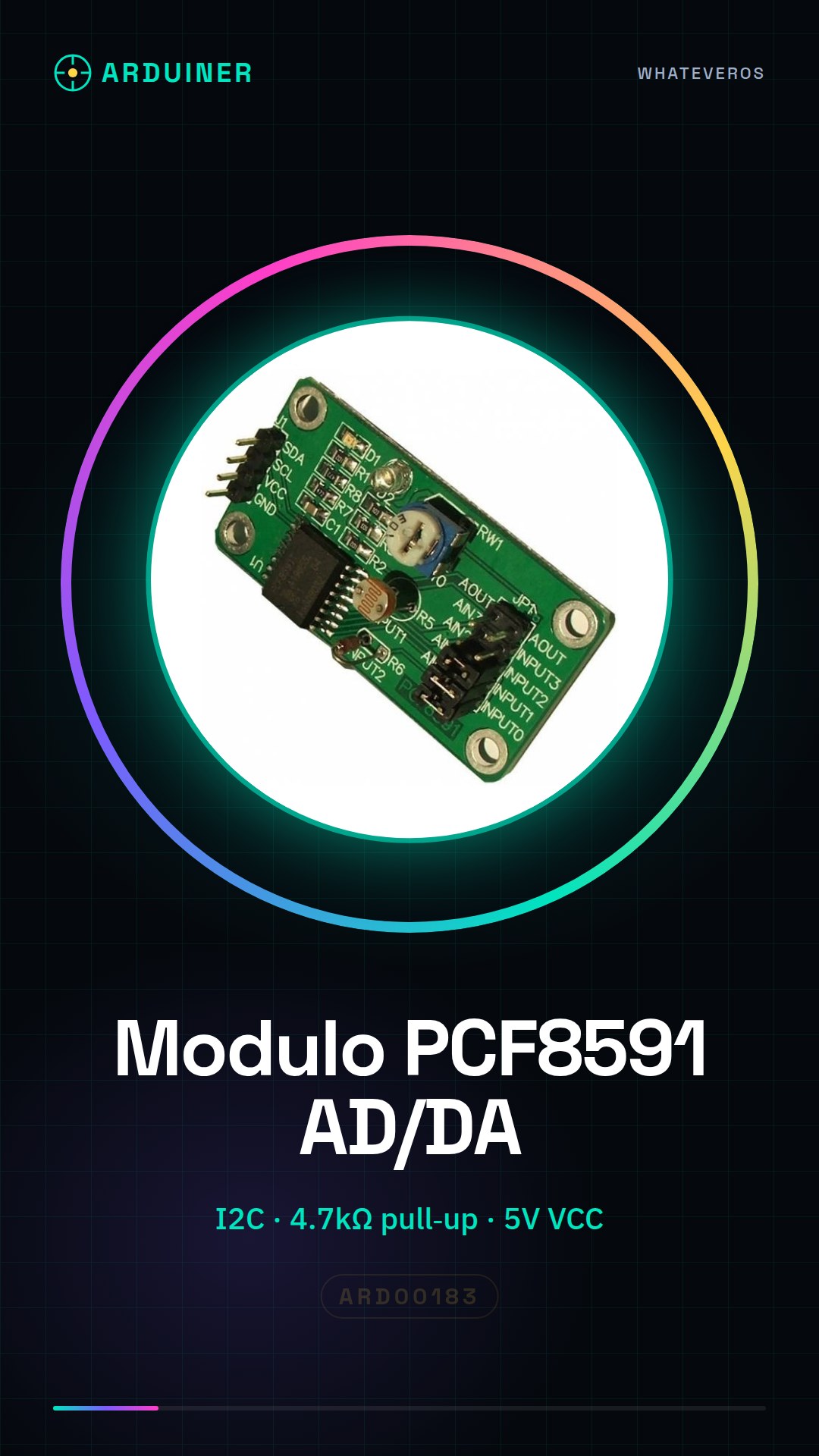
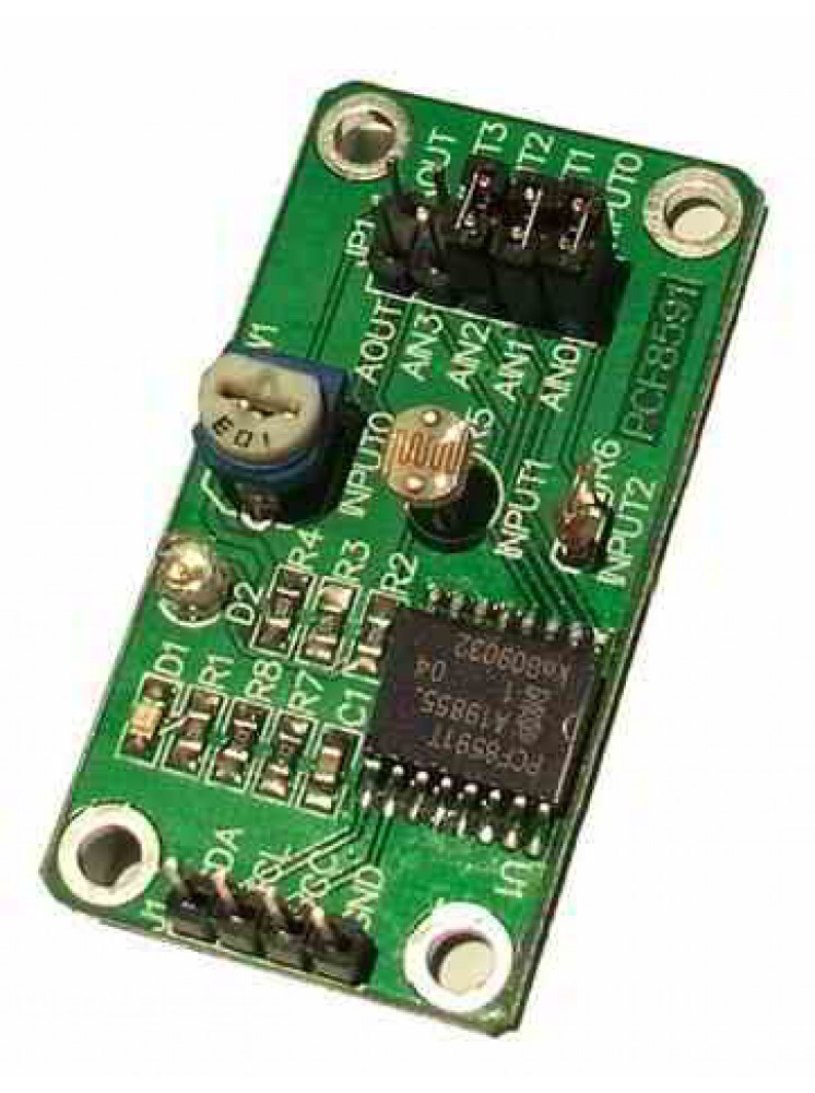
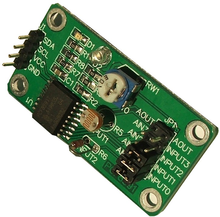
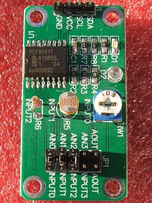
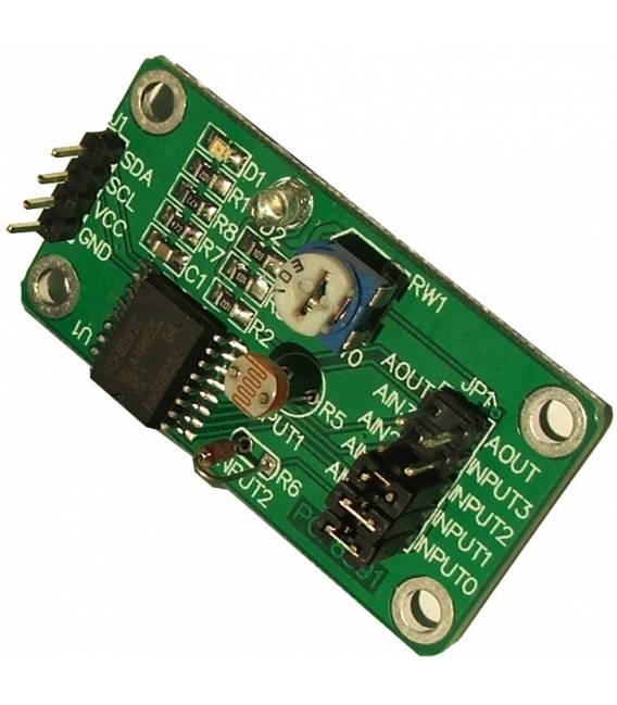
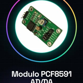
The PCF8591 module is an analog-to-digital (AD) and digital-to-analog (DA) converter that allows the reading and generation of analog signals through the I2C interface. It provides four analog input channels and one analog output channel, making it useful for measuring and controlling analog variables in electronic projects.
The module supports I2C communication, allowing direct connection to devices such as Arduino and Raspberry Pi. To ensure electronic stability, it is necessary to connect a pull-up resistor between the SCL pin and the power supply VCC.
The module configuration requires the installation of the Adafruit_PCF8591 library in Arduino IDE and the configuration of the PCF8591 I2C pin. The module is designed to operate in a stable and controlled environment, where the quality of the connection and software configuration are crucial.
Key Specifications
| Parameter | Value |
| Model | PCF8591 |
| Number of AD Channels | 4 |
| Number of DA Channels | 1 |
| Interface | I2C |
| Supply Voltage | N/D (see manufacturer’s datasheet) |
| Dimensions | N/D (see manufacturer’s datasheet) |
| Container | N/D (see manufacturer’s datasheet) |
Installation and Usage
- Connect VCC to the 5V pin of the microcontroller.
- Connect GND to the GND pin of the microcontroller.
- Connect SDA and SCL to the respective I2C pins of the microcontroller.
- Add the Adafruit_PCF8591 library to Arduino IDE.
- Configure the I2C pin of the PCF8591 (e.g., 0x48).
Compatibility and Requirements
- The PCF8591 module is compatible with Arduino and Raspberry Pi.
- A microcontroller that supports the I2C interface is required.
- The Adafruit_PCF8591 library is required for configuration.
Limitations and Important Notes
- The module does not support simultaneous read and write on all channels.
- The pull-up resistance between SCL and VCC is essential for system stability.
- I2C pin configuration must be accurate to avoid communication errors.
- The quality of the electronic connection can affect system stability.
Troubleshooting
The module does not respond to I2C communication.
Probable cause: Incorrect I2C pin configuration.
Solution: Verify the I2C pin configuration in the code.
Incorrect reading of analog values.
Probable cause: Incorrect connection of I2C pins.
Solution: Check the connections of SDA and SCL pins.
Stability issues during reading.
Probable cause: Missing pull-up resistance.
Solution: Connect a pull-up resistance between SCL and VCC.
Incorrect writing of analog values.
Probable cause: Incorrect DA channel configuration.
Solution: Check the DA channel configuration in the code.
Use cases
Measurement of ambient temperature.
Objective: Detect temperature with an analog sensor.
What is needed: PCF8591, temperature sensor, Arduino.
Steps: 1) Configure the PCF8591 module. 2) Connect the temperature sensor. 3) Read the analog values. 4) Convert the values to temperature.
Expected result: Precise measurement of ambient temperature.
Control of a DC motor.
Objective: Regulate the speed of the motor.
Needed: PCF8591, Arduino, DC motor.
Steps: 1) Configure the PCF8591 module. 2) Connect the DC motor. 3) Generate analog values to control speed.
Expected result: Precise motor speed control.
Ambient light indicator.
Objective: Measure ambient light.
Needed: PCF8591, Arduino, light sensor.
Steps: 1) Configure the PCF8591 module. 2) Connect the light sensor. 3) Read analog values. 4) Display light values.
Expected result: Functional ambient light indicator.
RGB LED control.
Needed: PCF8591, Arduino, RGB LED.
Steps: 1) Configure the PCF8591 module. 2) Connect the RGB LED. 3) Generate analog values to control colors.
Expected result: Precise RGB LED color control.
Atmospheric pressure measurement.
Objective: Detect atmospheric pressure.
What is needed: PCF8591, Arduino, pressure sensor.
Steps: 1) Configure the PCF8591 module. 2) Connect the pressure sensor. 3) Read analog values. 4) Convert values to pressure.
Expected result: Precise atmospheric pressure measurement.
Control of an irrigation system.
Objective: Regulate irrigation based on light.
What is needed: PCF8591, Arduino, light sensor.
Steps: 1) Configure the PCF8591 module. 2) Connect the light sensor. 3) Generate analog values to control irrigation.
Expected result: Light-based irrigation control system.
Measurement of a circuit’s temperature.
What is needed: PCF8591, Arduino, temperature sensor.
Steps: 1) Configure the PCF8591 module. 2) Connect the temperature sensor. 3) Read analog values. 4) Convert values to temperature.
Expected Result: Precise measurement of the circuit temperature.
Control an alarm system.
Required: PCF8591, Arduino, light sensor.
Steps: 1) Configure the PCF8591 module. 2) Connect the light sensor. 3) Generate analog values to control the alarm system.
Expected Result: Light-based alarm control system.
In the package
- 1 piece
Complete the project
- ADS1115 16 Bit I2C Analog to Digital Converter ADC 4 Channels with Programmable Gain Amplifier: For reading analog signals on Arduino or Raspberry Pi.
- USB to RS485 Converter Supports Win7 XP Vista Linux Mac OS: For converting analog signals to digital with high precision.
- Serial RS232 – TTL Interface Module
Technical FAQs
How do I configure the pull-up resistor?
Connect a 4.7kΩ resistor between the SCL pin and VCC.
Which I2C pins can I use?
On the Raspberry Pi, use GPIO 3 (SDA) and 5 (SCL).
Which libraries are needed to use the module?
The Adafruit_PCF8591 library is required in Arduino IDE.
What common errors occur when using the module?
Incorrect I2C pin configuration, wrong I2C pin connections, omission of the 4.7kΩ pull-up resistor.
Tutorial: How to use PCF8591
The PCF8591 is an AD/DA converter module useful for measuring and controlling analog values on Arduino and Raspberry Pi. Ideal for precision projects.
What you need
- Arduino or Raspberry Pi
- PCF8591
- 4.7kΩ pull-up resistor
- I2C Connections
Steps
- 1. Module installation: connect VCC to 5V, GND to GND, SDA and SCL to the respective I2C pins.
- 2. Add the Adafruit_PCF8591 library in Arduino IDE.
- 3. Configure the I2C pin on the PCF8591 (e.g., 0x48).
- 4. Read the AD channels: `analogReadChannel(0)`. Check the datasheet.
- 5. Write to the channels USING: `analogWriteChannel(0, 128)`. Check the datasheet.
- 6. Test reading and writing with an LED.
- 7. Configure the pull-up resistor (4.7kΩ) between SCL and VCC.
- 8. Verify system stability.
Example code
```cpp
#include <Adafruit_PCF8591.h>

Adafruit_PCF8591 pcf;

void setup() {
  pcf.begin(0x48);
}

void loop() {
  int value = pcf.analogRead(0);
  Serial.println(value);
}
```
Mini project
Create a simple light status indicator using a PCF8591 to read ambient light and control an LED.
Common mistakes
- Omit the pull-up resistor configuration.
- Incorrectly connect the I2C pins.
- Use an I2C pin not supported by the PCF8591.
- Forget to add the Adafruit_PCF8591 library.
Recommended accessories
- LED
- Resistor
- Light sensors
- I2C cable
Frequently asked questions
How should I configure the pull-up resistor?
Connect a 4.7kΩ resistor between the SCL pin and VCC.
Which I2C pins can I use?
On the Raspberry Pi, use GPIO 3 (SDA) and 5 (SCL). On the Arduino, use the SDA and SCL pins.
Why do I need to check the datasheet?
The values specified in the datasheet are the most accurate for AD/DA operations.
Reviews
There are no reviews yet.