 EN
 IT Italiano
 ES Español
 FR Français
 DE Deutsch
Description
Product Description
Tutorial: How to Use IC NE555P
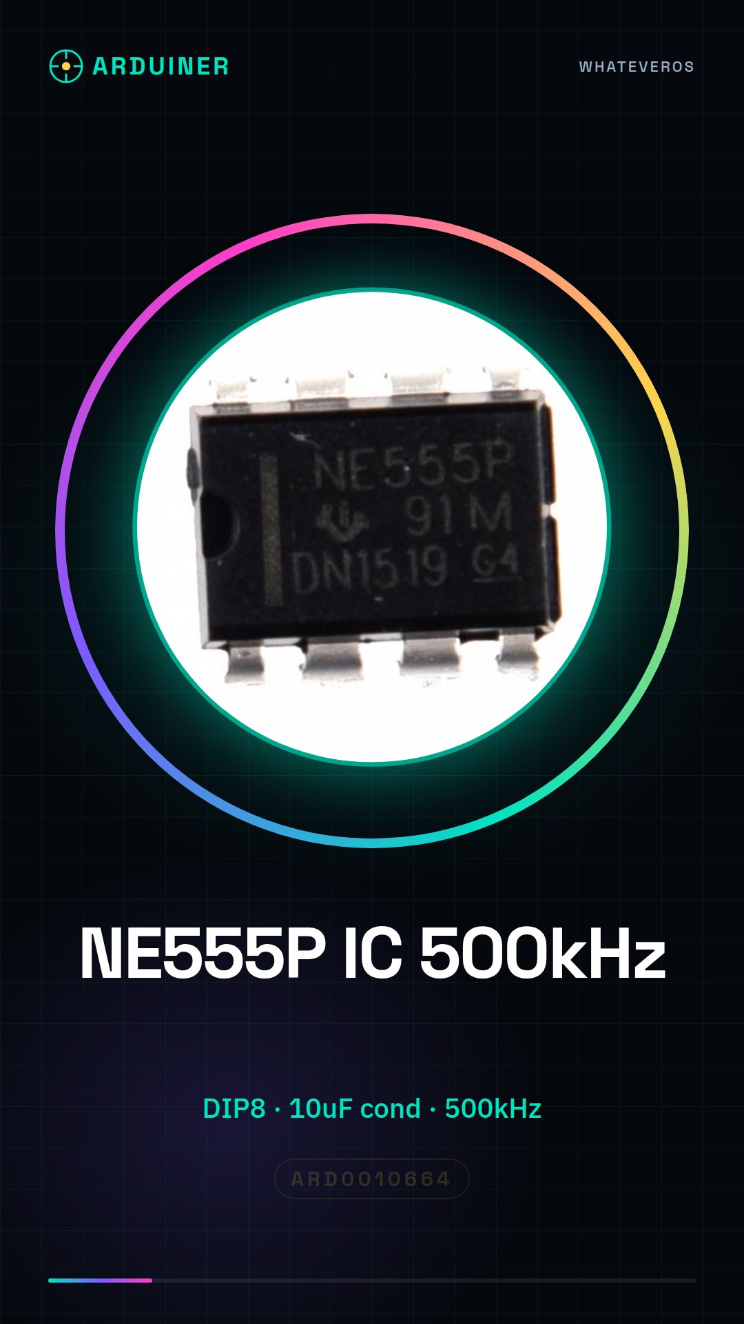
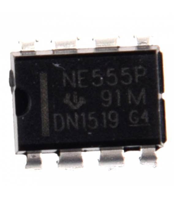
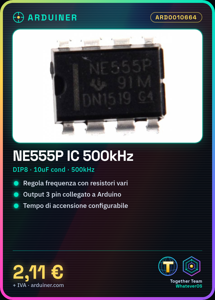
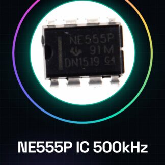
The IC NE555P is a fundamental component for creating timed circuits and signal generators. It is ideal for projects such as timers, oscillators, flip-flops, and more.
What you need
- Arduino Uno
- Prototype Printing
- 10uF Capacitor
- Various Resistors
Steps
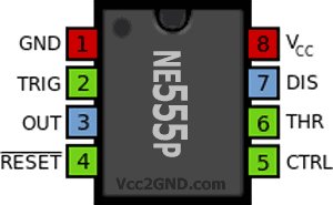
- Connect the 10uF capacitor between pins 2 and 4 of the IC NE555P.
- Connect the resistors to the terminals of the circuit to adjust the frequency and amplitude of the generated signals.
- Connect the positive power supply (+Vcc) to pin 8 of the IC NE555P, and ground (GND) to pin 1.
- Connect pin 3 (output) of the integrated circuit to a digital pin of an Arduino for reading the generated signals.
- Configure the Arduino with the appropriate sketch to read data from the NE555P.
Example code
void setup() {
pinMode(2, INPUT);
Serial.begin(9600);
}

void loop() {
digitalRead(2);
}
Mini project
Create a simple timer that turns on an LED lamp for 5 seconds every time a button is pressed.
Common mistakes
- Do not connect the capacitor with incorrect polarity
- Insert incorrect values for the resistors
- Configure the Arduino without uploading the appropriate sketch
Recommended accessories
- LED
- Push button
- Prototype printing for Arduino
- Kit of variable resistors
Frequently asked questions
What is the maximum frequency I can generate?
Check the datasheet of the NE555P.
Can I use this IC with 3V power supply?
Yes, but check the low voltage operation specifications in the datasheet.
Reviews
There are no reviews yet.