 EN
 IT Italiano
 ES Español
 FR Français
 DE Deutsch
Description
Technical Description
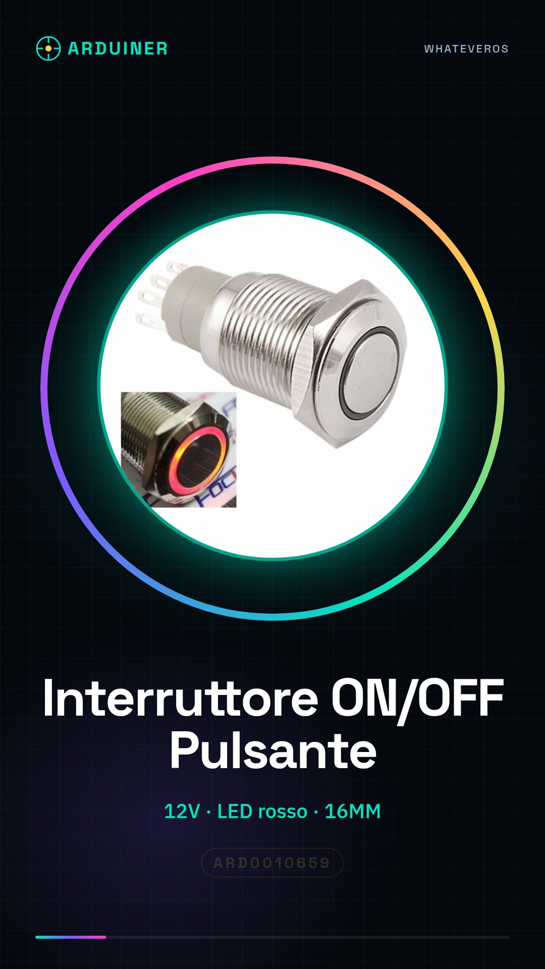
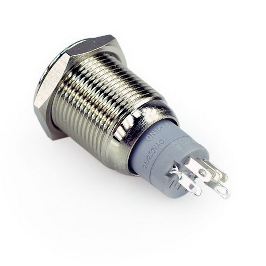
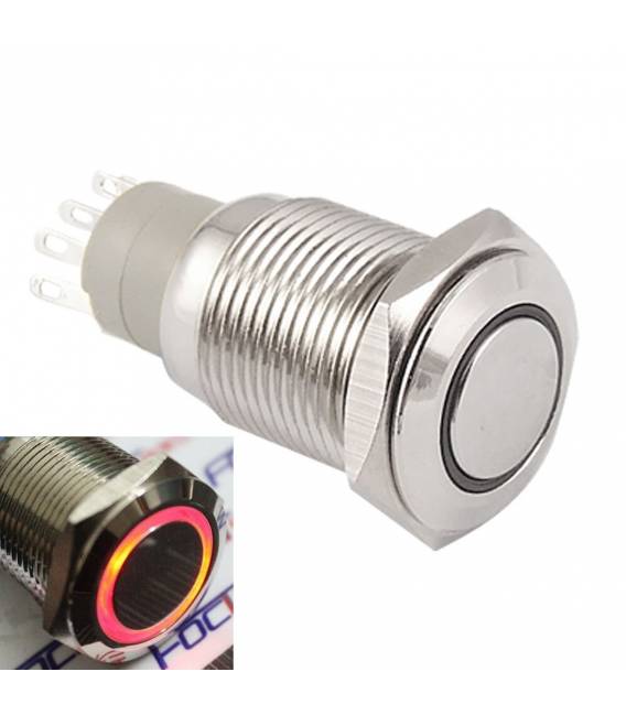
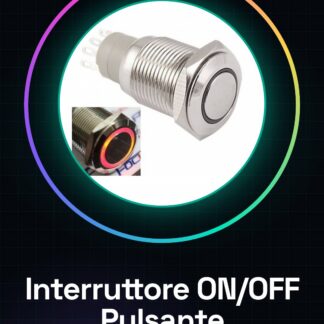
The self-locking push button ON/OFF switch with red LED 12V 16MM metal panel is an electronic component used for manual control of 12V powered electrical devices. The self-locking button allows the switch to remain in the ON or OFF position once activated, until it is released again. The red LED indicates the activation status of the switch. This switch is designed to be mounted on panels or rigid surfaces and can be used in various electronic projects and applications.
For its use, the switch must be correctly connected to the power supply circuit of the device to be controlled and to a digital input pin of an Arduino or another control board. Make sure to check the electrical compatibility and proper protection of the digital pins with any resistors.
The switch is suitable for applications where direct and visible manual control of the activation state of an electrical device is necessary.
Key Specifications
| Parameter | Value |
| Model | Push-On/Off Switch with Auto-Lock LED Red 12V 16MM |
| Operating Voltage | 12V |
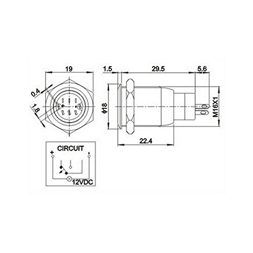
| Dimensions | 16MM |
| Materials | Metal |
| Switch Type | Auto-Lock |
| LED Color | Red |
| Mounting Type | Panel |
| Container | N/D (see manufacturer’s technical sheet) |
Installation and Usage
- Install the button on a panel or stable surface using the metal closure.
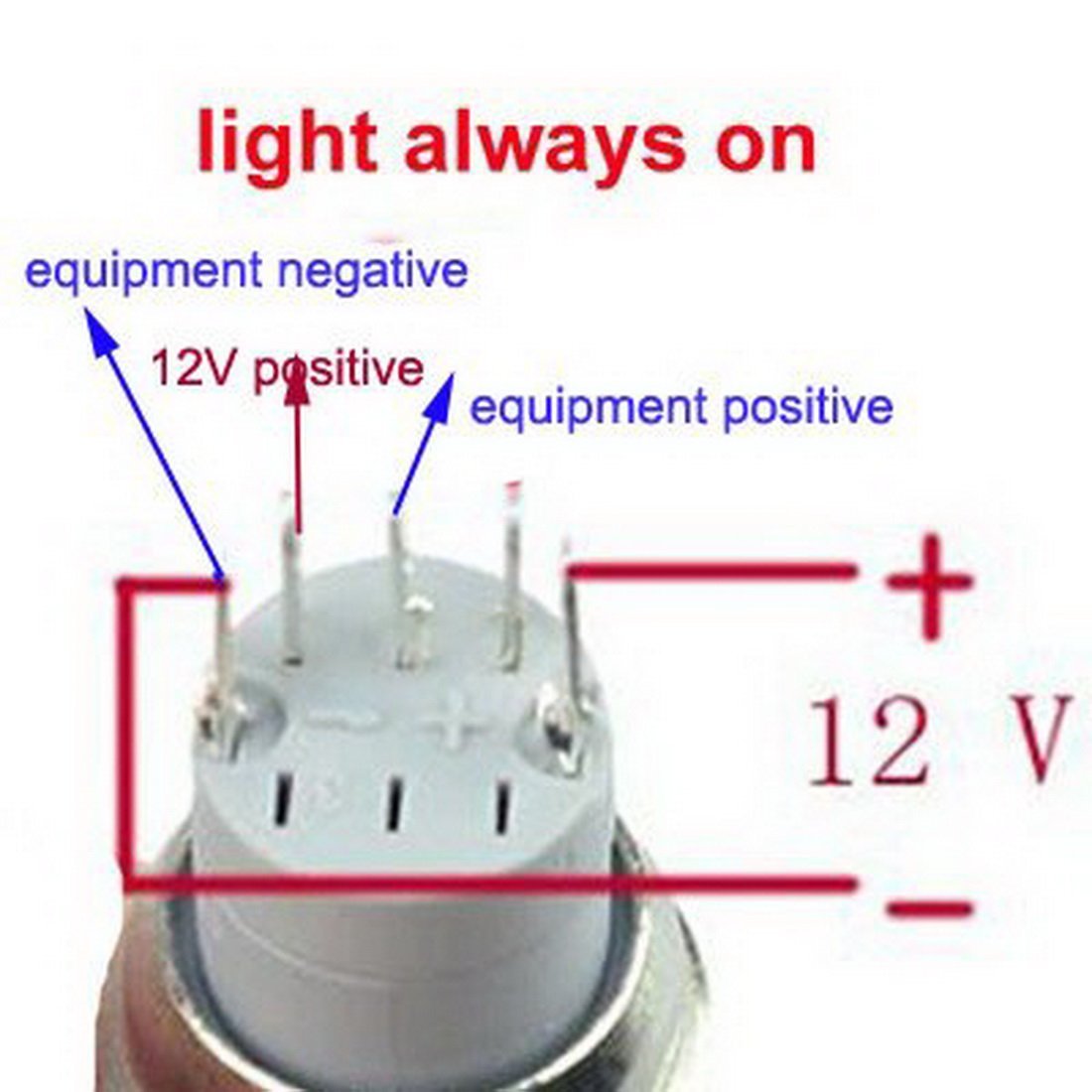
- Connect the ‘+’ and ‘-‘ lines of the switch to the device’s power circuit to be controlled.
- Connect the switch output to a digital input pin of the Arduino.
- Check the proper functioning of the system before using it in operational conditions.
- Add a resistor between the switch and the Arduino to protect the digital pin (if necessary).
Compatibility and Requirements
- This switch is compatible with Arduino Uno and other electronic control boards.
- A connection cable is required to connect the switch to the Arduino.
- A 12V battery is required to power the device.
- For project configuration, it is recommended to have additional software to manage the switch state.
Limitations and Important Notes
- The switch cannot be used for devices powered by voltages different from 12V.
- It is important to verify electrical compatibility before connecting the switch to the circuit.
- It is not recommended to use the switch without digital pin protection with resistors.
- The system must be adequately tested before operational use.
Troubleshooting
The LED does not light up.
Probable cause: The connection between the switch and the Arduino is incorrect.
Solution: Check the connections and ensure that the switch is correctly connected to a digital input pin of the Arduino.
The device does not respond.
Probable cause: The power supply circuit is not correctly connected.
Solution: Check the power circuit connections and ensure they are correct.
The system is not functioning properly.
Probable cause: The system was not adequately tested before use.
Solution: Test the system during charging and discharging phases to verify stability.
The button does not lock properly.
Probable cause: The locking mechanism may be damaged.
Solution: Check the locking mechanism and replace the switch if necessary.
Use cases
Automatic lighting system
Objective: Create an automatic lighting system from 12V.
What is needed: Push-button self-locking ON/OFF switch, red LED, Arduino Uno, connection cable, 12V battery, LED lamp.
Steps: 1) Install the switch on the panel. 2) Connect the switch to the lamp’s power circuit. 3) Connect the switch to a digital input pin of the Arduino. 4) Write an Arduino sketch to manage the state of the switch. 5) Test the system.
Expected result: The automatic lighting system is functioning and controlled by the button.
Motors control
Objective: Control the operation of a motor.
What you need: Push-button self-locking ON/OFF switch with red LED, Arduino Uno, connection cable, 12V battery, motor.
Steps: 1) Install the switch on the panel. 2) Connect the switch to the motor’s power circuit. 3) Connect the switch to a digital input pin of the Arduino. 4) Write an Arduino sketch to manage the state of the switch. 5) Test the system.
Expected result: The motor is controlled by the button.
Alarm system
Objective: Create an alarm system.
What you need: Push-button self-locking ON/OFF switch with red LED, Arduino Uno, connection cable, 12V battery, siren.
Steps: 1) Install the switch on the panel. 2) Connect the switch to the siren’s power circuit. 3) Connect the switch to a digital input pin of the Arduino. 4) Write an Arduino sketch to manage the state of the switch. 5) Test the system.
Expected result: The alarm system is functional and controlled by the button.
Fan control
Objective: Control the operation of a fan.
What you need: Push-button self-locking ON/OFF switch with red LED, Arduino Uno, connection cable, 12V battery, fan.
Steps: 1) Install the switch on the panel. 2) Connect the switch to the fan’s power circuit. 3) Connect the switch to a digital input pin of the Arduino. 4) Write an Arduino sketch to manage the state of the switch. 5) Test the system.
Expected result: The fan is controlled by the button.
Carillon Control System
Objective: Control the operation of a carillon.
What you need: Push-button self-locking ON/OFF switch with red LED, Arduino Uno, connection cable, 12V battery, carillon.
Steps: 1) Install the switch on the panel. 2) Connect the switch to the carillon’s power circuit. 3) Connect the switch to a digital input pin of the Arduino. 4) Write an Arduino sketch to manage the state of the switch. 5) Test the system.
Expected result: The chime is controlled by the button.
Control of an irrigation system
Objective: To control the operation of an irrigation system.
What you need: Self-locking push button switch with red LED, Arduino Uno, connection cable, 12V battery, irrigation pump.
Steps: 1) Install the switch on the panel. 2) Connect the switch to the pump’s power circuit. 3) Connect the switch to a digital input pin of the Arduino. 4) Write an Arduino sketch to manage the state of the switch. 5) Test the system.
Expected result: The irrigation system is controlled by the button.
Control of a security system
Objective: To control the operation of a security system.
Needed: Self-locking push button switch with red LED, Arduino Uno, connection cable, 12V battery, security system.
Steps: 1) Install the switch on the panel. 2) Connect the switch to the power supply circuit of the security system. 3) Connect the switch to a digital input pin of the Arduino. 4) Write an Arduino sketch to manage the state of the switch. 5) Test the system.
Expected result: The security system is controlled by the button.
Ventilation system control
Objective: Control the operation of a ventilation system.
Needed: Self-locking push button switch with red LED, Arduino Uno, connection cable, 12V battery, ventilation system.
Steps: 1) Install the switch on the panel. 2) Connect the switch to the ventilation system power circuit. 3) Connect the switch to a digital input pin of the Arduino. 4) Write an Arduino sketch to manage the state of the switch. 5) Test the system.
Expected result: The ventilation system is controlled by the button.
In the package
- 1 piece
Complete the project
- Green LED Push-On/Off Switch with Auto-Lock 12V 16MM Metal Panel: to use an alternative green LED switch
Technical FAQs
How to verify the compatibility of the circuit with 12V power supply?
Check the device’s datasheet to ensure the operating voltage is 12V.
Why does the device not work?
Check the power circuit connections and ensure they are correct.
How to protect the digital pins of the Arduino?
Add a resistor between the switch and the Arduino to protect the digital pin.
What are the steps to test the system?
Test the system during charging and discharging phases to verify stability.
Tutorial: How to use Push Button Self-Locking ON/OFF Switch with Red LED 12V
This ON/OFF switch with push button self-locking and red LED is ideal for controlling 12V devices such as lamps, motors, or any other electrical device. It is perfect for both beginners and more experienced makers.
What you need
- Arduino Uno
- Connection cable
- 12V battery
- Connectors
Steps
- Install the button in a panel or stable surface using the metal closure.
- Connect the ‘+’ and ‘-‘ lines of the switch to the power circuit of the device to be controlled (check the datasheet for specific details).
- Connect the switch output to a digital input pin of the Arduino.
- Write an Arduino sketch that reads the state of the switch and activates/deactivates the connected device (check the datasheet for specific details).
- Verify the correct functioning of the system before using it in operational conditions.
- If necessary, add a resistor between the switch and the Arduino to protect the digital pin (check the datasheet for specific details).
- Test the stability of the system during charging and discharging phases.
- Configure any additional software to manage the state of the switch.
Mini project
Create an automatic 12V lighting system using this switch, an LED lamp, and an Arduino. The project can be completed in about 30 minutes.
Common mistakes
- Do not verify the circuit’s compatibility with 12V power supply.
- Omit the connection between the switch and a digital pin of the Arduino.
- Ignore the protection of digital pins with resistors.
- Do not adequately test the system before use.
Recommended accessories
- Resistor to protect digital pins
- 12V battery
- Mounting panel
- Connector kit
Frequently asked questions
Can the switch be used with voltages below 12V?
Check the datasheet for compatibility.
How can I protect my circuit from current spikes?
Add a fuse or voltage regulator to the circuit.
Reviews
There are no reviews yet.