 EN
 IT Italiano
 ES Español
 FR Français
 DE Deutsch
Description
FTDI Breakout Converter USB to TTL Serial ASP 6 PIN 5V for MWC Multiwii Arduino
Description:
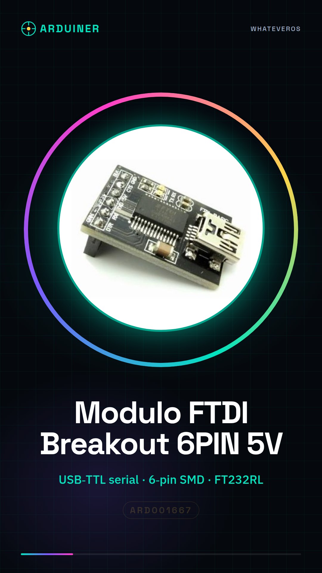
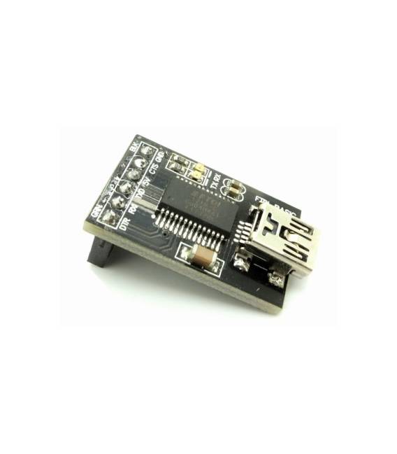
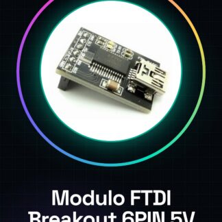
This is the latest revision of our FTDI BASIC. It now uses a 6-pin SMD header on the bottom, making it smaller and more compact. The functionality remains the same.
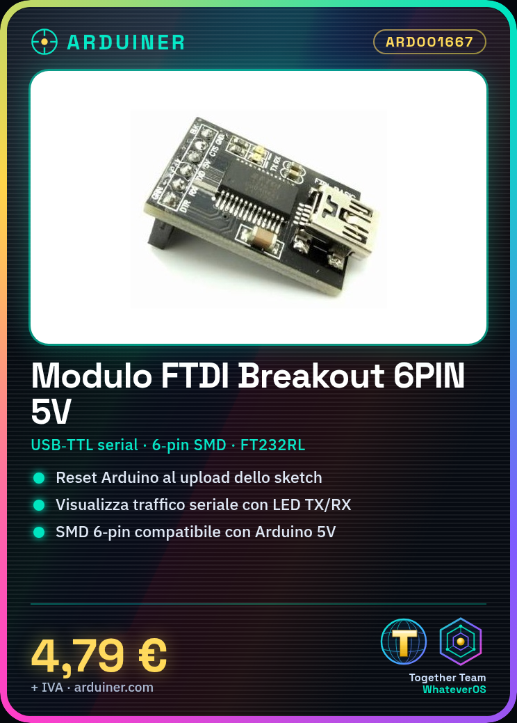
This is a basic breakout board for FTDI FT232RL USB to serial IC. The pinout of this board matches the FTDI cable to work with official Arduino boards and 5V cloned Arduino boards.
It can also be used for general serial applications. The main difference with this board is that it highlights the DTR pin in contrast to the RTS pin of the FTDI cable.
The DTR pin allows an Arduino target to automatically reset when a new sketch is uploaded. This is a really nice feature to have and allows for sketch upload without having to press the reset button.
This board will automatically reset any Arduino board that has the reset pin brought out to a 6-pin connector.
The pins labeled BLK and GRN correspond to the colored wires on the FTDI cable. The black wire on the FTDI cable is GND, the green is CTS. Use these BLK and GRN pins to align your base FTDI board to your target Arduino.
This board has TX and RX LEDs that make it a bit easier to use with the FTDI cable. You can actually see the serial traffic on the LEDs to check if the board is working.
We have datasheets available for all components, should they not be present in the product download. If you do not find them, send us a message from the contact us module and we will publish them as soon as possible on our website.
Tutorial: How to use FTDI Breakout Module USB to TTL Serial Converter
The FTDI Breakout module is a crucial component for serial communication between a computer and Arduino boards or other microcontrollers. It is ideal for beginners in electronics who want to easily send data to and from their projects.
What you need
- Computer with USB port
- USB A to B or Micro-B cable
- Arduino or other microcontroller
Steps
- Connect the FTDI module to the computer via a USB cable
- Check that the TX and RX pins of the module are correctly connected to the pins of the Arduino board
- Install the necessary library to manage the FTDI (usually provided with the Arduino IDE)
- Write a simple sketch in Arduino IDE that sends data to the serial port
- Open the serial monitor in Arduino IDE and verify the reception of the data
- Configure communication settings (baud rate, parity, etc.) in the computer software
- Verify the proper functionality of the module with a simple example provided in the FTDI datasheet
- Test the connection by reversing TX and RX to check for connection errors
Example code
void setup() {
  Serial.begin(9600);
}

void loop() {
  Serial.println("Messaggio da Arduino");
}
Mini project
Create a projectile that sends data from the temperature sensor to the Arduino and then to the computer through the FTDI module
Common mistakes
- Incorrect connection between TX and RX
- Incorrect serial settings (baud rate, parity)
- Missing library required for the FTDI
- Unstable USB connection
Recommended accessories
- DS18B20 Temperature Sensor
- USB A to Micro-B Cable
- Arduino Uno R3
- 3D Print FTDI Connection Prototype
Frequently asked questions
Why is the FTDI module not communicating with the Arduino?
Check that TX and RX are correctly connected and verify the serial settings in the software.
What baud rates does the FTDI module support?
Check the module datasheet for specific supported baud rate values.
Reviews
There are no reviews yet.