 EN
 IT Italiano
 ES Español
 FR Français
 DE Deutsch
Description
What it is
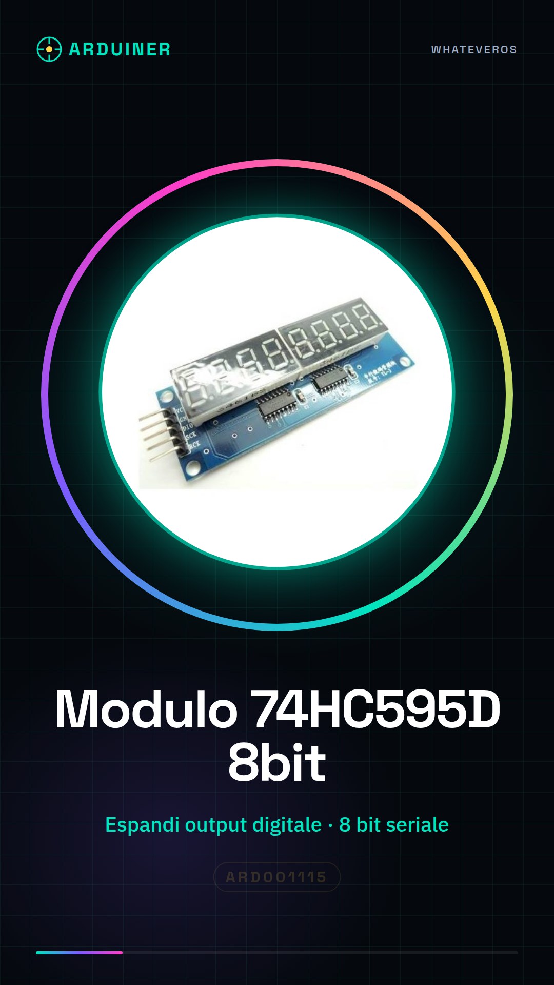
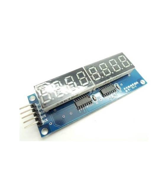
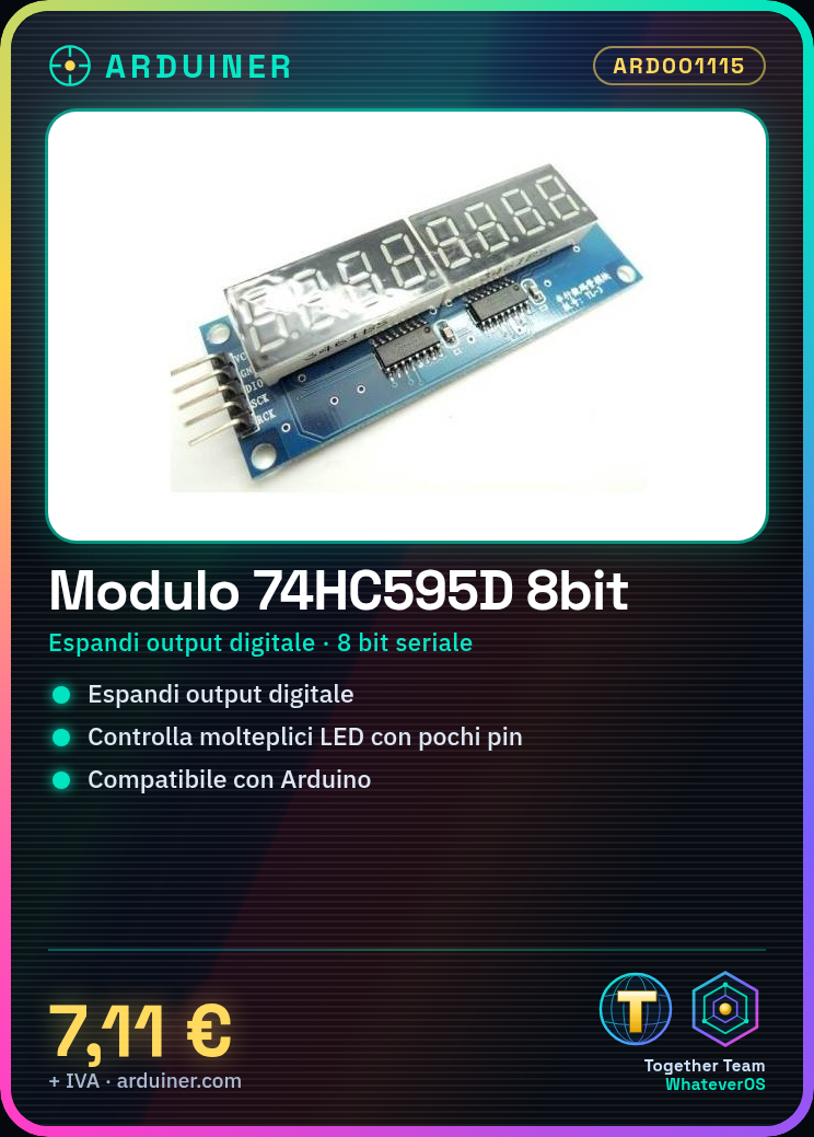
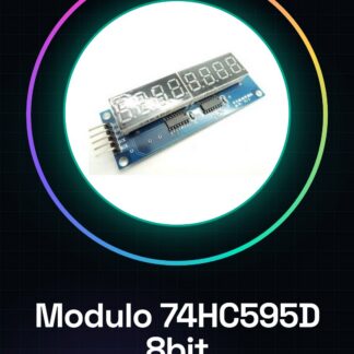
The 8-bit serial digital microcontroller module 74HC595D is an electronic component used to expand the digital output capacity in Arduino projects. It is particularly useful for managing LED matrices, where it allows controlling a large number of LEDs or digital pins with few microcontroller pins.
Features
- 8-bit serial digital microcontroller
- For managing LED matrices and other digital ports
What it is for
It is used for projects that require managing a large number of LEDs or digital pins with few microcontroller pins. It is compatible with Arduino and can be used in various scenarios such as LED matrices, multiple segment displays, and any other case where there is a need to expand the digital output capacity.
Tutorial: How to use Shift Register Module 74HC595D
The 74HC595D shift register module is an essential electronic component for makers who want to control a large number of LEDs or other digital outputs with few pins of the microcontroller. It is ideal for projects such as LED matrices, multiple segment displays, and any other scenario where there is a need to expand digital output capacity.
What you need
- Arduino Uno or compatible
- USB cable to connect the Arduino to the computer
- Connections such as jumper wire
- LEDs
Steps
- Connect the pins of the 74HC595D module to those of the Arduino as follows: VCC to 5V, GND to GND, SER (DS) to a digital output pin of the Arduino, RCLK (SRCLK) to another digital pin, and SRCLR (RCLR) to ground with a pull-up resistor.
- Open the Arduino IDE and install the ShiftRegister library if it is not already present.
- Write a sketch that uses the 74HC595D module to turn on or off the LEDs connected to its outputs.
- Load the sketch onto the Arduino and verify that everything works correctly.
Example code
// Includi la libreria ShiftRegister
#include <ShiftRegister.h>

// Definisci i pin dell'Arduino utilizzati per il modulo 74HC595D
const int latchPin = 8;
const int dataPin = 12;
const int clockPin = 11;

void setup() {
  // Inizializza i pin del modulo
  ShiftRegister::begin(latchPin, clockPin, dataPin);
}

void loop() {
  // Accendi tutti i LED collegati al modulo
  ShiftRegister::allOn();
  delay(1000);

  // Spegni tutti i LED collegati al modulo
  ShiftRegister::allOff();
  delay(1000);
}
Mini project
Design and build an 8×8 LED matrix using 4 shift register modules 74HC595D. The matrix can be programmed to display various visual effects such as sparks, flows, or custom patterns.
Common mistakes
- Incorrect pin connection of the module
- ShiftRegister library not installed
- Error in the memory address used to access the module registers
- Problems with the voltage applied to the module
Recommended accessories
- 8×8 LED matrix
- LEDs of various colors
- 220 ohm resistors
- USB type B cable
Frequently asked questions
How can I connect multiple 74HC595D modules?
Connect the SER (DS) pin of the next module to the QH’ (output) of the first, RCLK (SRCLK) and SRCLR (RCLR) must be shared among all modules.
What is the difference between 74HC595D and SN74HC164N?
The 74HC595D has 8 outputs, while the SN74HC164N has only 8 in series. The 74HC595D is more suitable for controlling LED matrices or digital ports.
Reviews
There are no reviews yet.