 EN
 IT Italiano
 ES Español
 FR Français
 DE Deutsch
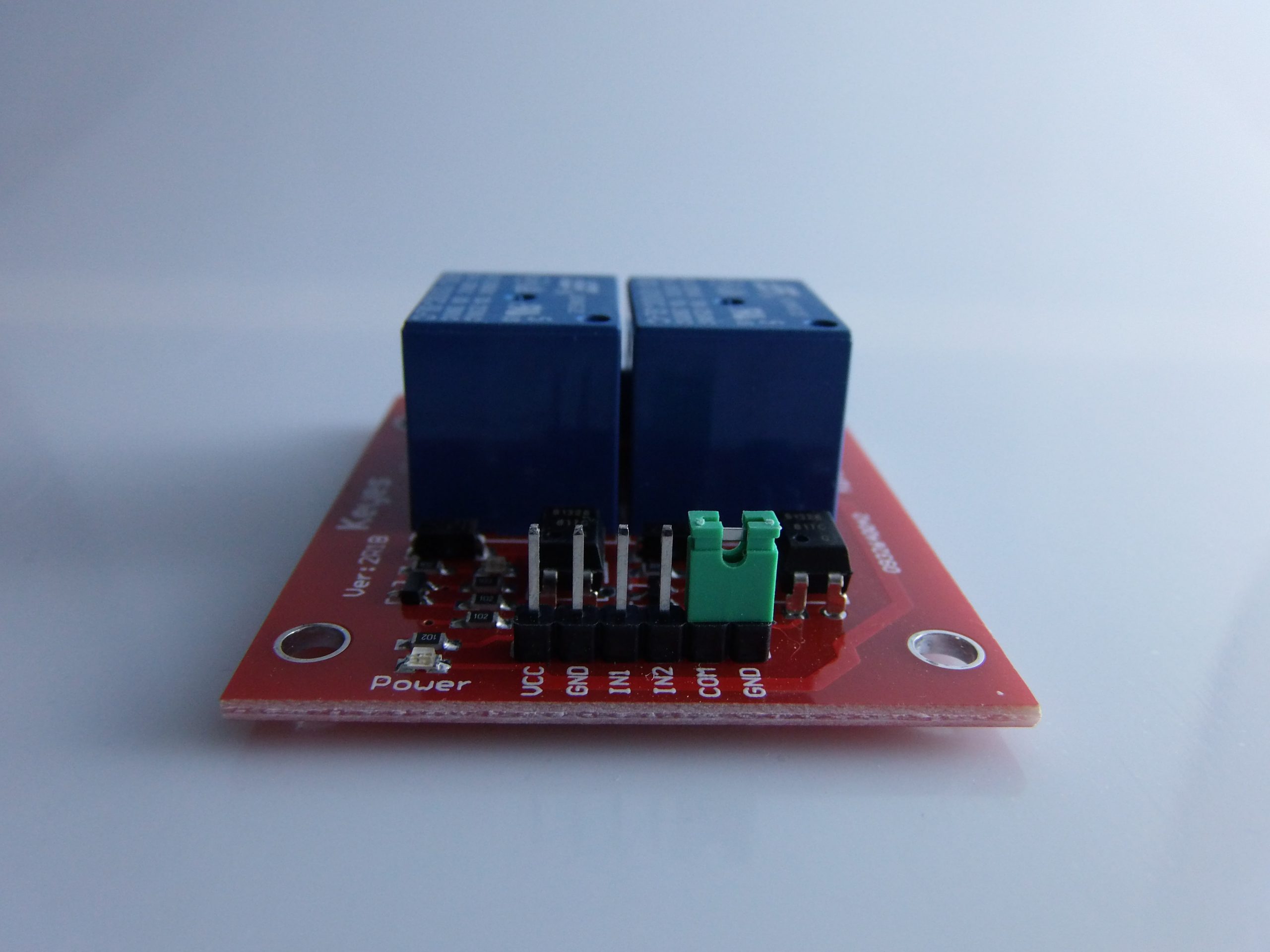
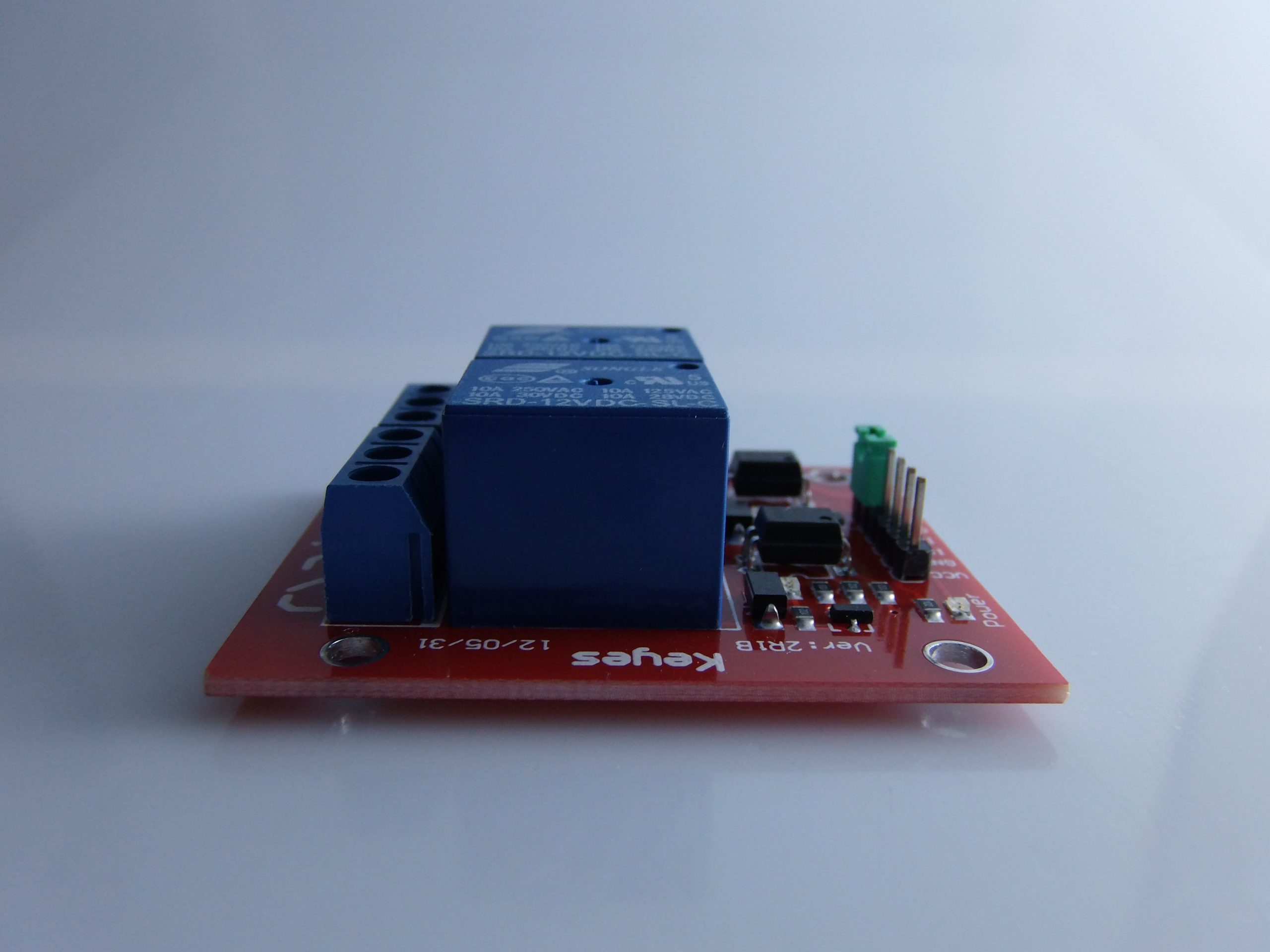
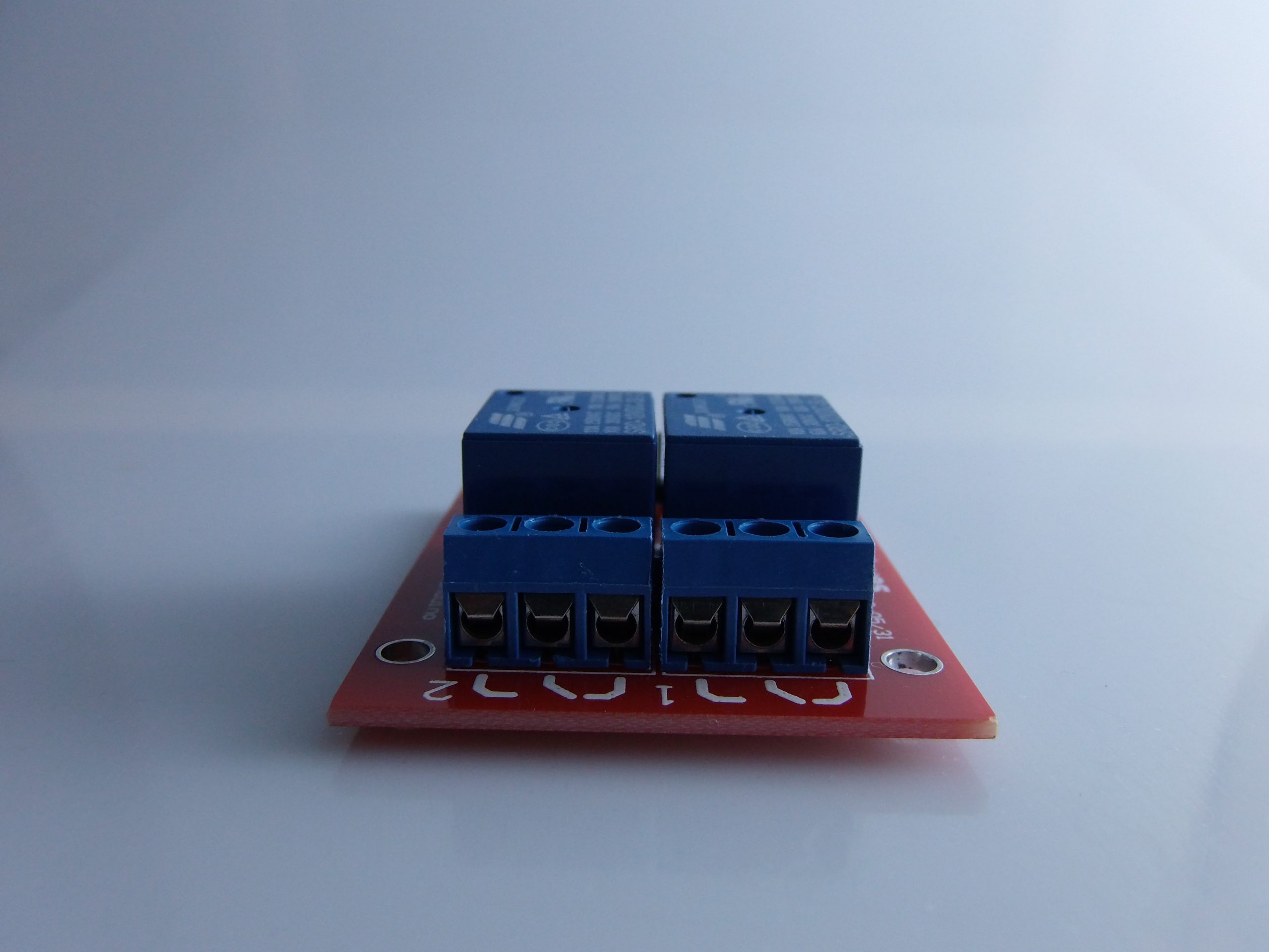
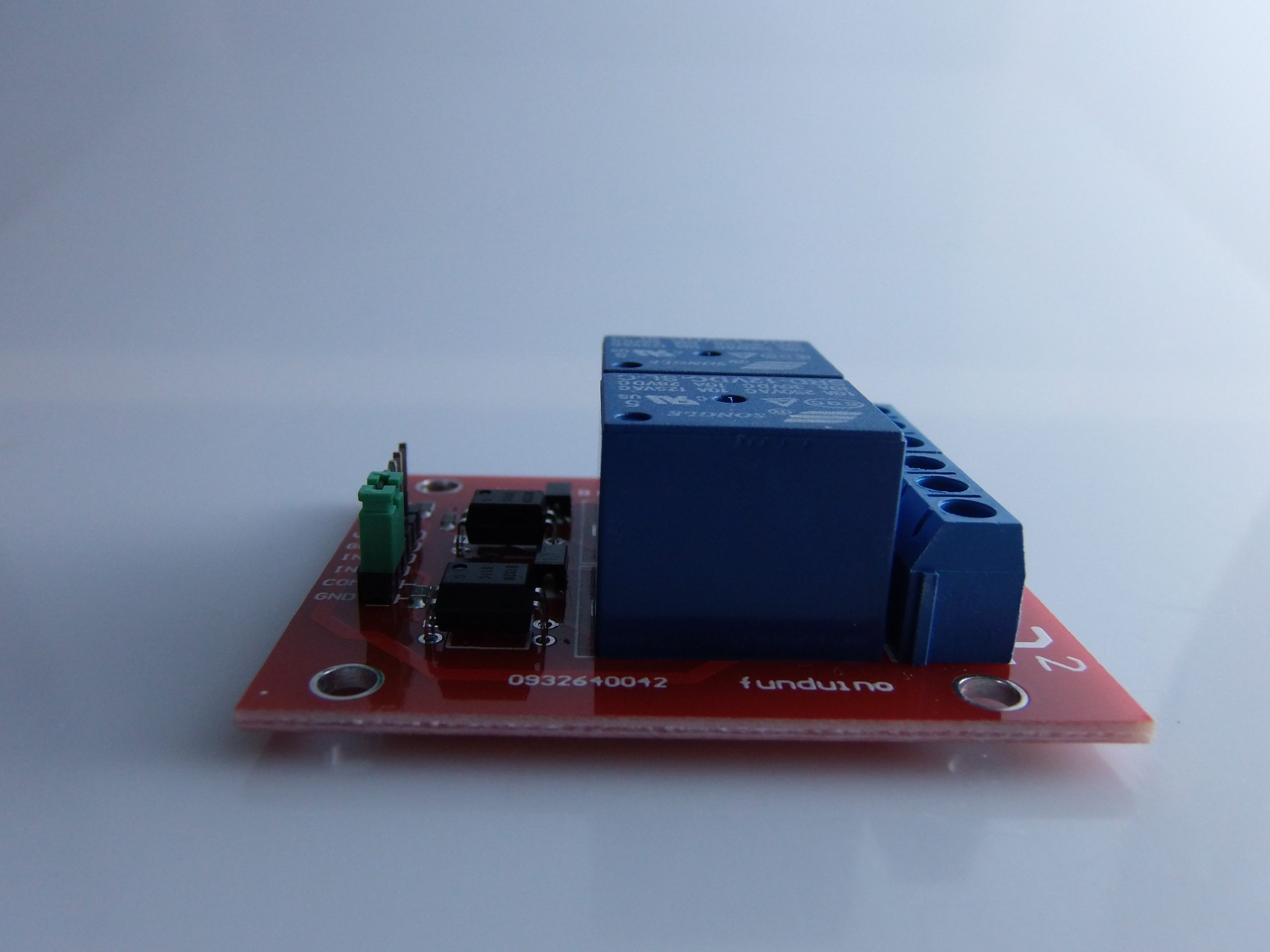
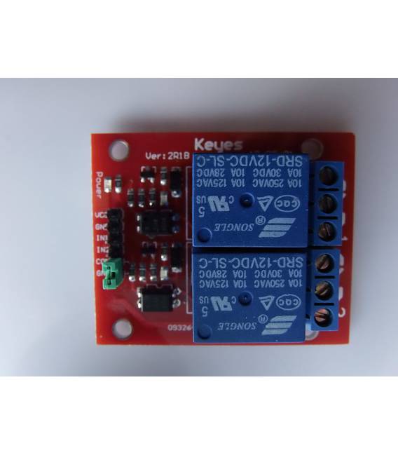
Description
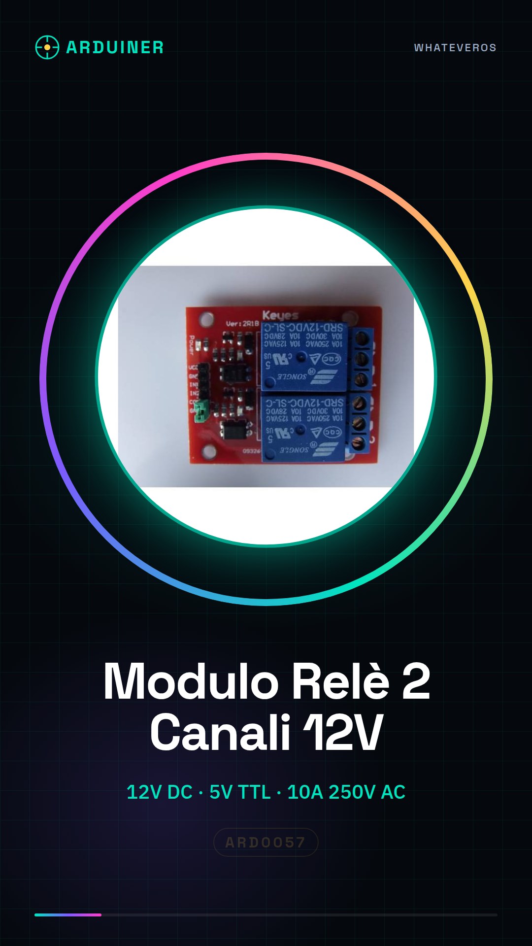
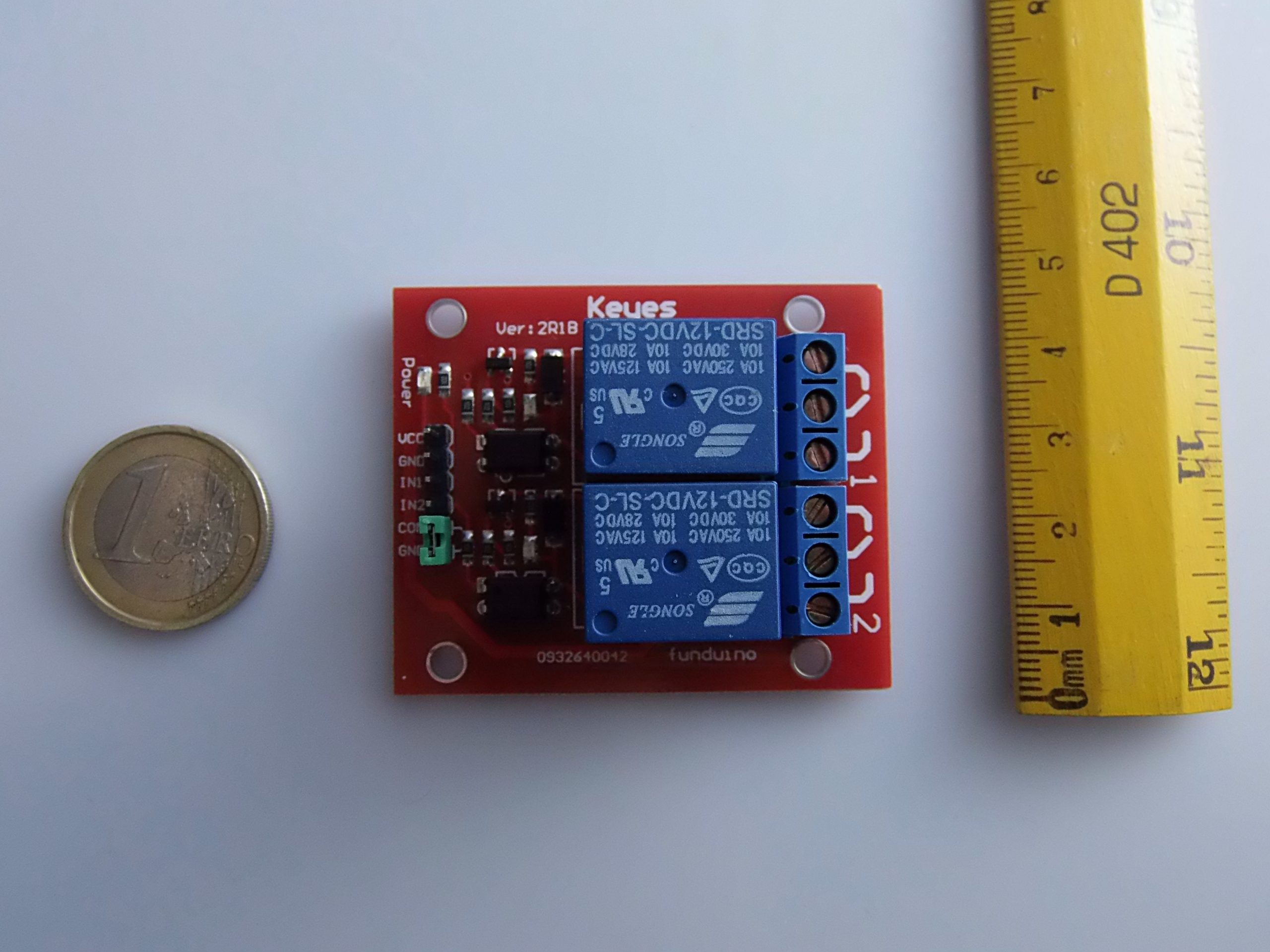
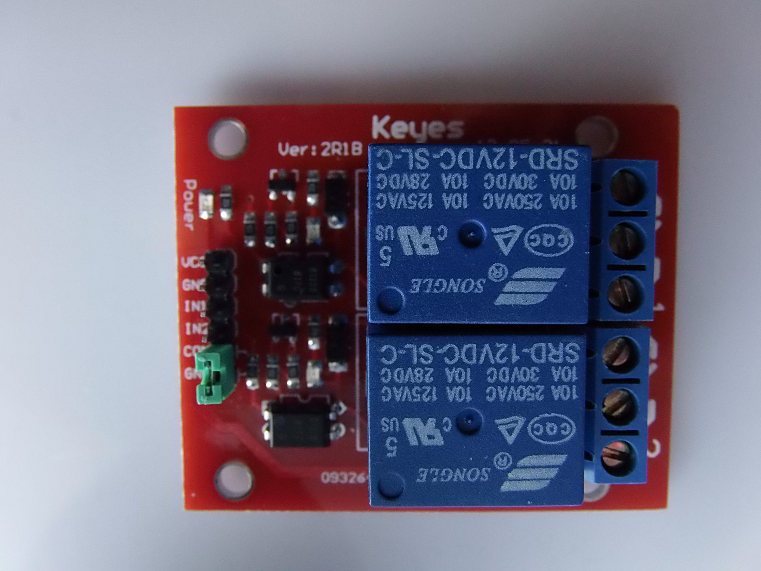
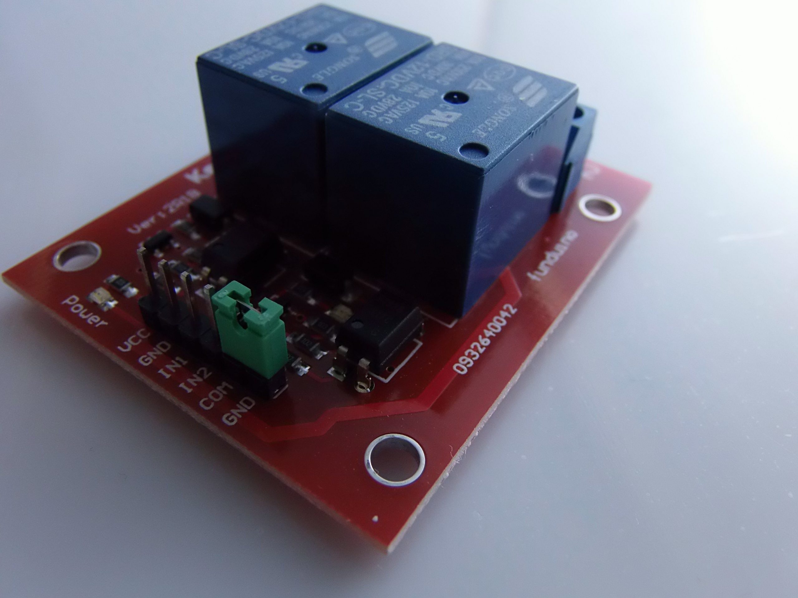
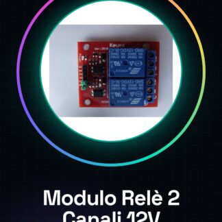
Description 2 Channel 12V Relay Module
The 2 Channel 12V Relay Module is an electronic module that allows controlling high voltage electrical loads (up to 250V AC or 30V DC) using low voltage signals from microcontrollers such as Arduino, PIC, ARM, AVR, DSP, etc.
Main Features:
- Number of Channels: 2 independent relays
- Supply Voltage: 12V DC for the module
- Control Voltage (input): 5V TTL (compatible with Arduino and most microcontrollers)
- Type of relay: Electromechanical relay with normally open (NO), normally closed (NC) and common (COM) contacts
- Maximum Current: Generally up to 10A (depends on the specific model) at 250V AC or 30V DC
- LED Indicator: An LED for each channel that lights up when the relay is activated
- Opto-isolator isolation: Many modules have insulation between the control circuit and the high-voltage circuit, increasing safety
- Dimensions: Compact, easy to integrate into DIY projects
Operation:
The module receives a 5V digital signal (HIGH/LOW) from the microcontroller pins. When the signal is HIGH, the relay activates, closing the circuit on the load side, allowing current to pass and turning on the connected device.
How to use the 2-channel relay module with Arduino
Required materials:
- Arduino Uno (or any other model)
- 2-channel relay module 12V
- 12V power supply for the relay module (or external power supply)
- Jumper wires
- Load to control (light bulb, motor, solenoid, etc.)
Hardware connections:
| Relay Module | Arduino Uno | Description |
|---|---|---|
| VCC | 12V DC (external power supply) | Module power supply (be careful not to power from Arduino 5V) |
| GND | GND Arduino + GND power supply | Common ground between Arduino and module |
| IN1 | Digital pin Arduino (e.g. D7) | Control relay 1 |
| IN2 | Digital pin Arduino (e.g. D8) | Control relay 2 |
| COM1, NO1, NC1 | Load 1 | Connect the load to be controlled |
| COM2, NO2, NC2 | Load 2 | Connect the second load |
Note: The module power supply must be provided externally at 12V, because the relay requires this voltage to function correctly. Ensure that the GND of the module is connected to the GND of Arduino for a common reference.
Programming with Arduino
Here is an example of basic code to alternate and activate the two relays every 2 seconds:
// Definizione dei pin di controllo dei relè
const int rele1 = 7;
const int rele2 = 8;

void setup() {
 // Impostiamo i pin dei relè come output
 pinMode(rele1, OUTPUT);
 pinMode(rele2, OUTPUT);

 // Disattiviamo entrambi i relè all'inizio (LOW = relè spento)
 digitalWrite(rele1, LOW);
 digitalWrite(rele2, LOW);
}

void loop() {
 // Attiva il relè 1, disattiva il relè 2
 digitalWrite(rele1, HIGH);
 digitalWrite(rele2, LOW);
 delay(2000); // aspetta 2 secondi

 // Disattiva il relè 1, attiva il relè 2
 digitalWrite(rele1, LOW);
 digitalWrite(rele2, HIGH);
 delay(2000); // aspetta 2 secondi
}
How the code works:
- In
setup()the relay pins are initialized as outputs. - In
loop()the relays are alternated every 2 seconds: first the first relay is turned on and the second is turned off, then vice versa.
Useful tips for programming and using the module
- Inverted signal: Some relay modules activate with a LOW signal (0V) instead of HIGH (5V). In this case, you need to invert the logic in the code (
LOWto activate,HIGHto deactivate). - Separate power supply: Use an external power supply for the 12V module to avoid overloading Arduino.
- Protection: Do not connect high voltage loads directly to Arduino pins! Always use the relay as a switch.
- Isolation: If possible, choose modules with optoisolators for electrical safety.
- Suitable load: Check the maximum current and voltage supported by the relay to avoid damage.
Perfect! I’ll prepare an advanced guide with practical examples of using the 2 channel relay module with Arduino, integrating remote control via Bluetooth and usage with sensors.
Advanced Guide: Control 2 Channel Relay Module with Arduino + Bluetooth + Sensors
1. Remote Control via Bluetooth
Additional Material:
- Bluetooth Module HC-05 or HC-06
- Arduino Uno
- 2 Channel Relay Module 12V
- 12V Power Supply for Relay
Essential Connections:
| Bluetooth Module HC-05 | Arduino Uno | Function |
|---|---|---|
| VCC | 5V | Power |
| GND | GND | Ground |
| TX | Pin 10 (RX) | Data reception from Arduino |
| RX | Pin 11 (TX) | Data transmission from Arduino |
Also connect the relay module pins as before (IN1 -> pin 7, IN2 -> pin 8).
Example code: relay control via Bluetooth commands
#include <SoftwareSerial.h>

SoftwareSerial BTSerial(10, 11); // RX, TX

const int rele1 = 7;
const int rele2 = 8;

void setup() {
 pinMode(rele1, OUTPUT);
 pinMode(rele2, OUTPUT);
 digitalWrite(rele1, LOW);
 digitalWrite(rele2, LOW);

 Serial.begin(9600);
 BTSerial.begin(9600);
 Serial.println("Modulo Relè Bluetooth pronto.");
}

void loop() {
 if (BTSerial.available()) {
 char comando = BTSerial.read();
 Serial.print("Ricevuto comando: ");
 Serial.println(comando);

 switch(comando) {
 case '1': // Accendi relè 1
 digitalWrite(rele1, HIGH);
 break;
 case '2': // Spegni relè 1
 digitalWrite(rele1, LOW);
 break;
 case '3': // Accendi relè 2
 digitalWrite(rele2, HIGH);
 break;
 case '4': // Spegni relè 2
 digitalWrite(rele2, LOW);
 break;
 default:
 Serial.println("Comando non riconosciuto");
 }
 }
}
2. Automatic control with temperature sensor (example with DHT11/DHT22 sensor)
Additional materials:
- Temperature and humidity sensor DHT11 or DHT22
- DHT library for Arduino (installable from Library Manager)
Connections:
| DHT11/22 sensor | Arduino Uno | Function |
|---|---|---|
| VCC | 5V | Power Supply |
| GND | GND | Ground |
| DATA | Pin 2 | Data (with 10k pull-up resistor) |
Example Code: Turn on a relay if temperature > 30°C
#include <DHT.h>

#define DHTPIN 2
#define DHTTYPE DHT11

DHT dht(DHTPIN, DHTTYPE);

const int rele1 = 7;

void setup() {
 Serial.begin(9600);
 dht.begin();

 pinMode(rele1, OUTPUT);
 digitalWrite(rele1, LOW);
}

void loop() {
 float temp = dht.readTemperature();
 if (isnan(temp)) {
 Serial.println("Errore lettura sensore");
 return;
 }
 Serial.print("Temperatura: ");
 Serial.print(temp);
 Serial.println(" °C");

 if (temp > 30) {
 digitalWrite(rele1, HIGH); // accendi il relè
 } else {
 digitalWrite(rele1, LOW); // spegni il relè
 }
 delay(2000);
}
3. Advanced Usage Ideas
- Automatic Timer: turn on a load for a certain period, then turn it off automatically.
- WiFi Control: using ESP8266 or ESP32 modules, you can integrate relays with web servers or smartphone apps.
- Security Management: add current sensors to prevent overloads or damage.
- Integration with Voice Assistants: connect Arduino to platforms like Alexa via bridge.
|
GENERAL |
MODEL |
2 Channel 12V Relay Module |
|
MATERIALS |
pcb + components |
|
|
COMPATIBILITY |
ARDUINO |
|
|
ELECTRICAL COMPONENTS |
INPUT VOLTAGE |
12 V |
|
WEIGHT AND DIMENSIONS |
PRODUCT WEIGHT |
20g |
|
PACKAGE WEIGHT |
0.35 kg |
|
|
PRODUCT DIMENSIONS (L x W xH) |
5.6 x 4.8 x 4.5 cm |
|
|
PACKAGE DIMENSIONS (L x W x H) |
10 x 15 x 5 cm |
|
|
PACKAGE CONTENT |
1 x Module |
We have available the technical sheet of all components, if it is not present in the product download card, send us a message through the contact form and we will publish it as soon as possible on our website.
Tutorial: How to use 2 Channel 12V Relay Module
This 2-channel relay module allows you to control electrical devices from Arduino or other microcontrollers. Ideal for beginners who want to start with automation.
What you need
- Arduino Uno
- USB Cable
- 12V Battery
Steps
- Connect the relay module to your computer via USB cable.
- Connect the VCC and GND pins of the module to corresponding pins on the Arduino.
- Connect the command lines (IN1, IN2) to the digital pins of the Arduino.
- Check the datasheet for the resistor to connect between the microcontroller and the relay input to limit the current.
- Write the sketch that activates/deactivates the relays based on the desired conditions.
- Load the sketch onto Arduino using Arduino IDE.
- Check the datasheet for the control pin specifications (IN1, IN2) to ensure the correct operation of the module.
- Test the activation/deactivation of the relays with various commands from Arduino.
Example code
void setup() {
 pinMode(7, OUTPUT);
pinMode(8, OUTPUT);
}

void loop() {
digitalWrite(7, HIGH); // Attiva il relè del canale 1
delay(2000);
digitalWrite(7, LOW); // Disattiva il relè del canale 1
delay(2000);
}
Mini project
Create an automatic lighting system: connect 12V lamps to the relays and control the switching with Arduino based on data from sensors.
Common mistakes
- Incorrect pin connection of VCC/GND
- Omission of the current limiting resistor.
- Use of voltages higher than specified for the relay (max 12V).
- Incorrect choice of control pin without checking the specifications on the datasheet.
Recommended accessories
- Relay Shield for Arduino
- Light sensors
- Battery 9-12V
- Extension cable
Frequently asked questions
How can I control multiple relays?
Connect multiple modules or use a module with more channels.
What is the operating voltage of the relay?
12V max, check the datasheet for specific details.
Reviews
There are no reviews yet.