 EN
 IT Italiano
 ES Español
 FR Français
 DE Deutsch
Description
Technical Specifications
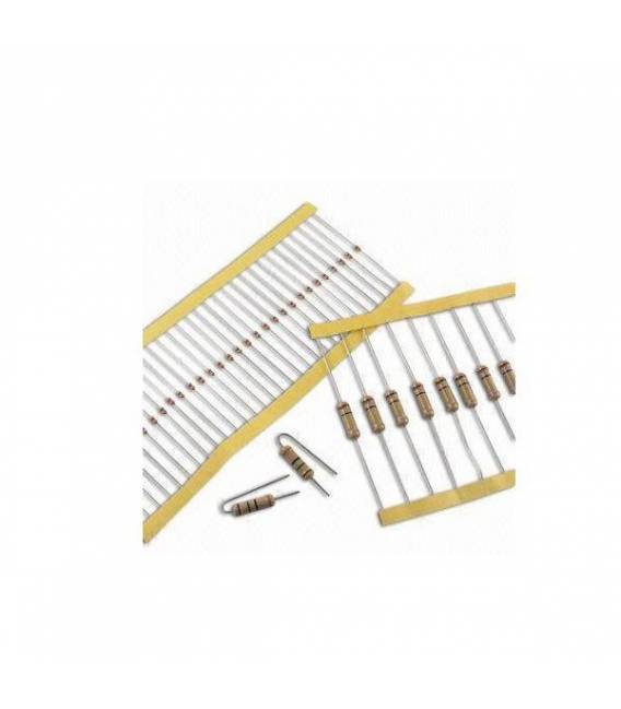
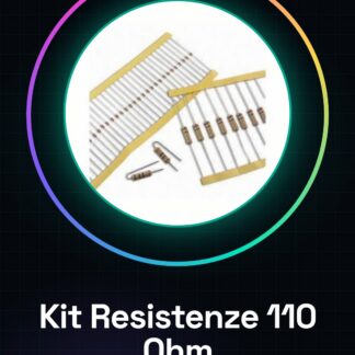
The 110 Ohm 1/4W 5% Resistor Kit contains 50 pieces of resistors with a resistance of 110 Ohm and a maximum power of 1/4 Watt. These resistors are used to limit the flow of current in electronic circuits, protect sensitive components from overvoltage, and regulate voltage levels. The resistance value tolerance is 5%, ensuring a certain variation in specific values.
Resistors are available in an organized container to facilitate their management and use in various electronic projects. To use these resistors, it is necessary to connect them correctly to the circuits, check the technical specifications, and ensure that the resistance value is adequate for the project requirements.
The kit is suitable for laboratory experiments and tests, Arduino prototyping and projects, offering great flexibility and a reserve of essential components.
Key Specifications
| Parameter | Value |
| Model | 110 Ohm 1/4W 5% Resistor Kit |
| Quantity | 50 pieces |
| Resistor | 110 Ohm |
| Power | 1/4W |
| Tolerance | 5% |
| Dimensions | N/D (see manufacturer’s datasheet) |
| Container | Organized for 50 pieces |
Installation and Usage
- Check the resistor specifications in the datasheet.
- Use a multimeter to verify the value of the resistor.
- Connect the resistor to a digital pin of the Arduino using JST/Molex cables or breadboards.
- Change the state of the digital pin in Arduino IDE (HIGH and LOW) to test the current flow.
- Verify the read values with a multimeter.
Compatibility and Requirements
- This resistor kit is compatible with Arduino Uno and compatible boards.
- An Arduino Uno or compatible board is required to test and use the resistors.
- JST/Molex cables or breadboards are required to connect the resistors to circuits.
Limitations and Important Notes
- These resistors cannot be used in circuits requiring a resistance higher than 110 Ohm.
- It is necessary to check the technical specifications before using the resistors.
- It is recommended to use an appropriate limiting resistor when connecting components to high voltages.
- It is necessary to protect sensitive components from overvoltage.
Troubleshooting
The resistance value does not match the expected value.
Probable cause: The resistance value tolerance is 5%, the value may vary.
Solution: Check the value with a multimeter and compare with technical specifications.
The component connected to the resistance does not work properly.
Probable cause: The resistance may not be adequate for the circuit requirements.
Solution: Check the technical specifications and ensure that the resistance value is adequate.
The component connected to the resistance burns out.
Probable cause: The resistance may not be able to handle the circuit power.
Solution: Check the resistance power and use a higher power resistance if necessary.
The value read by the multimeter is abnormal.
Probable cause: The resistor might be damaged or not connected properly.
Solution: Check the connection and the resistor with a multimeter.
Use cases
Light control system
Objective: Adjust the intensity of an LED through a button.
What’s needed: Arduino Uno, 110 Ohm resistors, LED, button.
Steps: 1) Connect the button to a digital pin of the Arduino. 2) Connect the LED to the digital pin of the Arduino through a 110 Ohm resistor. 3) Write a code to adjust the intensity of the LED based on the state of the button.
Expected result: The LED changes intensity based on the state of the button.
RC Circuit
Objective: Test the behavior of an RC circuit.
What’s needed: Arduino Uno, 110 Ohm resistors, capacitor.
Steps: 1) Connect the resistor and capacitor in series. 2) Connect the circuit to a digital pin of the Arduino. 3) Measure the charging and discharging time of the capacitor.
Expected result: The charging and discharging time of the capacitor is measured correctly.
Protection System
Objective: Protect a component from overvoltage.
Required: Arduino Uno, 110 Ohm resistors, sensitive component.
Steps: 1) Connect the resistor between the digital pin of the Arduino and the sensitive component. 2) Verify that the resistor correctly limits the current flow.
Expected result: The sensitive component is protected from overvoltage.
Voltage Divider
Objective: Adjust the voltage level.
Required: Arduino Uno, 110 Ohm resistors.
Steps: 1) Connect two resistors in series. 2) Measure the voltage between the resistors.
Expected result: The voltage level is adjusted correctly.
Resistance Test
Objective: Verify the resistance value.
What you need: Multimeter, 110 Ohm resistors.
Steps: 1) Connect the ends of the resistor to the multimeter. 2) Measure the resistance value.
Expected result: The resistance value is measured correctly.
Attenuation Circuit
Objective: Limit the flow of current.
What you need: Arduino Uno, 110 Ohm resistors.
Steps: 1) Connect the resistor between the power source and the component. 2) Measure the current flow.
Expected result: The current flow is limited correctly.
Temperature Control System
Objective: Regulate the temperature level.
What you need: Arduino Uno, 110 Ohm resistors, thermistor.
Steps: 1) Connect the thermistor and the resistor in series. 2) Measure the temperature using the thermistor.
Expected result: The temperature level is measured correctly.
Protection Circuit
Objective: Protect a circuit from overvoltage.
What you need: Arduino Uno, resistors 110 Ohm.
Steps: 1) Connect the resistor between the power supply and the circuit. 2) Verify that the resistor correctly limits the current flow.
Expected result: The circuit is protected from overvoltage.
In the package
- 50 pieces Resistors 110 Ohm 1/4W 5%
Complete the project
- 50 Pieces Resistor, 10000 ohm, 10k, ohm 1/4w 1/4 w 5% , Arduino compatible resistors: It is used to test resistors of different values.
- Kit Resistors 470 Ohm 1/4W 5% – 50 Pieces: It is used to test resistors of different values.
- Kit Resistors 330 Ohm 1/4W 5% – 50 Pieces: It is used to test resistors of different values.
- Kit Resistors 150 Ohm 1/4W 5% – 50 Pieces
- Kit Resistors 120 Ohm 1/4W 5% – 50 Pieces
Technical FAQs
What is the maximum power of the resistor?
The maximum power of the resistor is 1/4 Watt.
How do you connect a resistor to an LED?
Connect the anode pin of the LED to a digital pin on the Arduino and the other end of the LED to the resistor.
What is the tolerance of the resistance value?
The tolerance of the resistance value is 5%.
How do you verify the resistance value?
Verify the resistance value with a multimeter.
Tutorial: How to use 110 Ohm Resistor Kit
This resistor kit is ideal for Arduino projects and electronic prototypes. With 50 pieces, it offers great flexibility for experiments and testing.
What you need
- Arduino Uno or compatible
- JST/Molex cables
- breadboard
Steps
- Open the product datasheet to verify technical specifications.
- Verify the resistance with a multimeter.
- Connect the resistor to a digital pin on the Arduino using JST/Molex cables or breadboard.
- Change the state of the digital pin in Arduino IDE (HIGH and LOW) to test the current flow.
- Check the readings with a multimeter.
- If necessary, use the resistor as part of a voltage divider or an RC circuit.
- Test the resistor in various circuits to familiarize yourself with its applications.
- Store the kit in an organized container to preserve the integrity of the components.
Mini project
Create a simple illuminated control interface using Arduino and the 110 Ohm resistor. Connect the resistor to an LED and control it through a button connected to another digital pin.
Common mistakes
- Use an inadequate resistor for current attenuation.
- Do not check the technical specifications of the resistor before using it.
- Omit overvoltage protection when using with LEDs or detectors.
- Connect a component directly to high voltage without an appropriate limiting resistor.
Recommended accessories
- Kit of LEDs in various colors
- Arduino compatible test panels
- JST/Molex cables for connecting components
- Arduino Uno or compatible
Frequently asked questions
What is the maximum power of the resistor?
Check the datasheet.
How do you connect a resistor to an LED?
Connect the anode pin of the LED to the digital pin of the Arduino and the other end to the resistor, then ground the resistor to limit current.
Reviews
There are no reviews yet.