 EN
 IT Italiano
 ES Español
 FR Français
 DE Deutsch
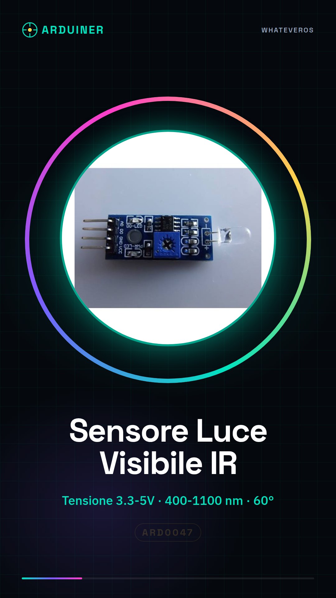
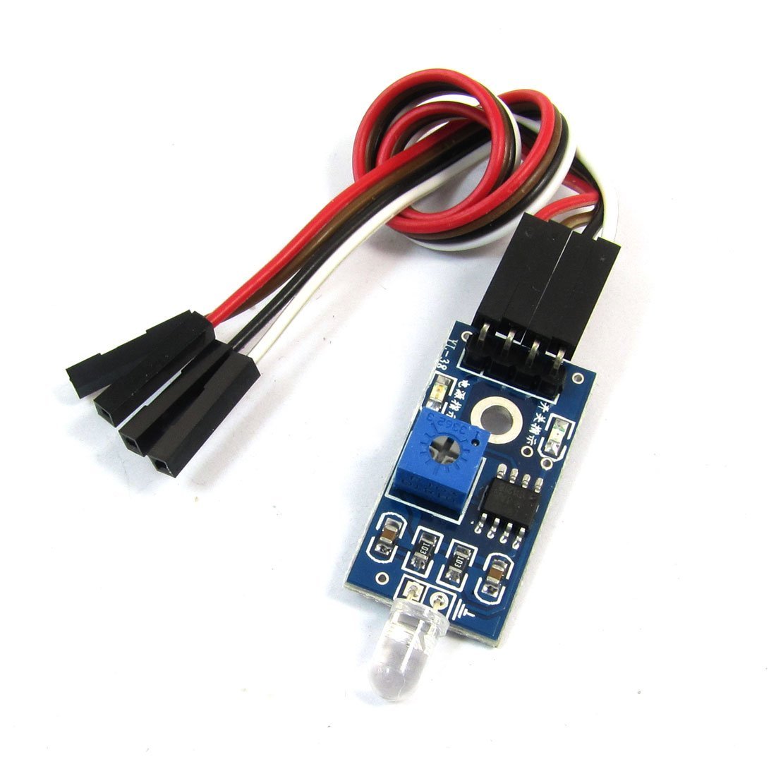
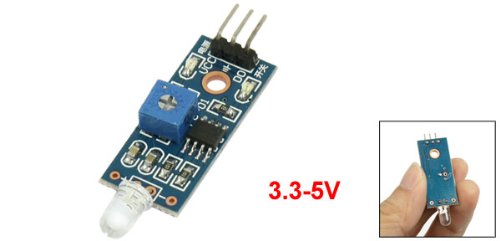
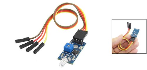
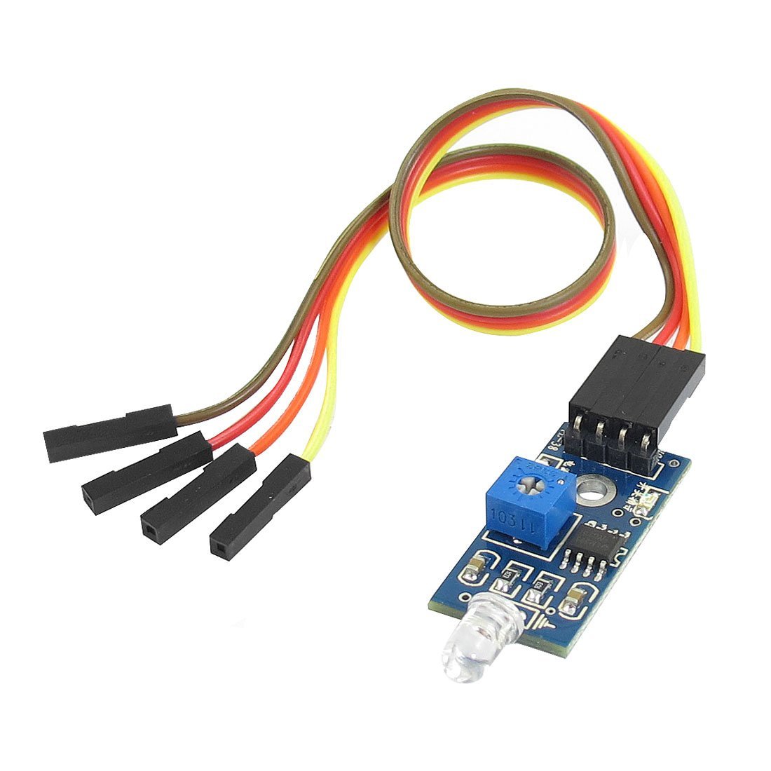
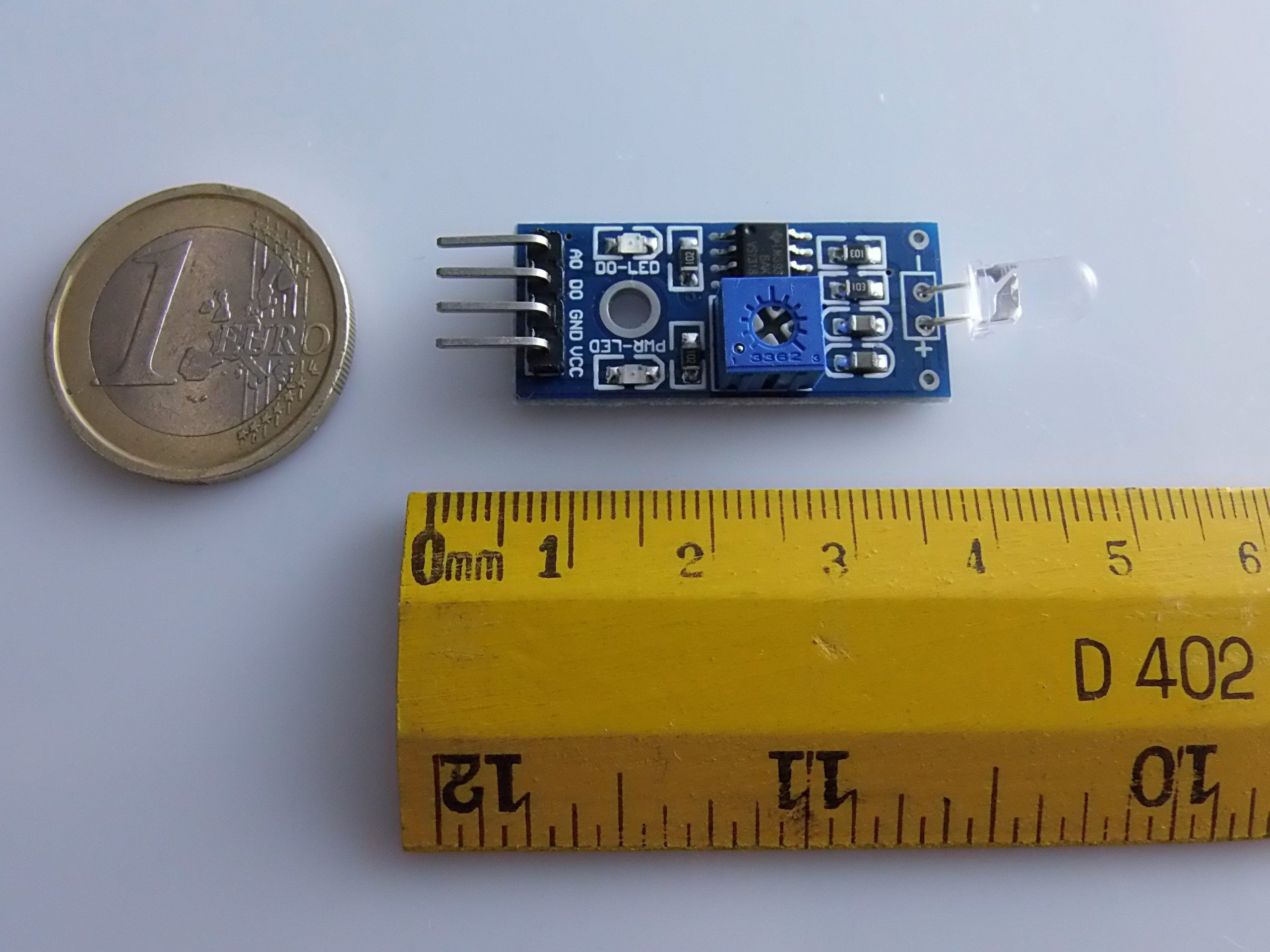
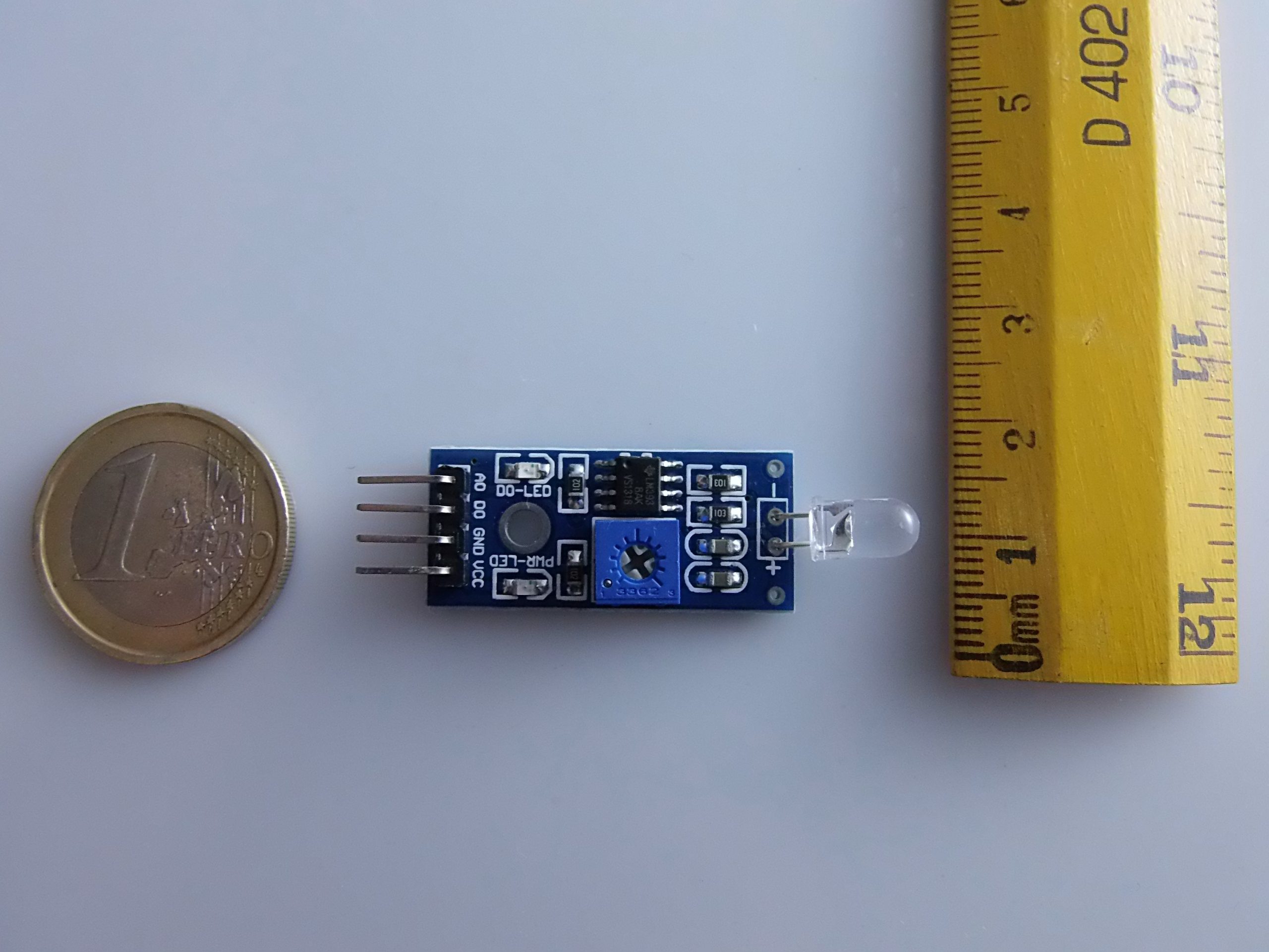
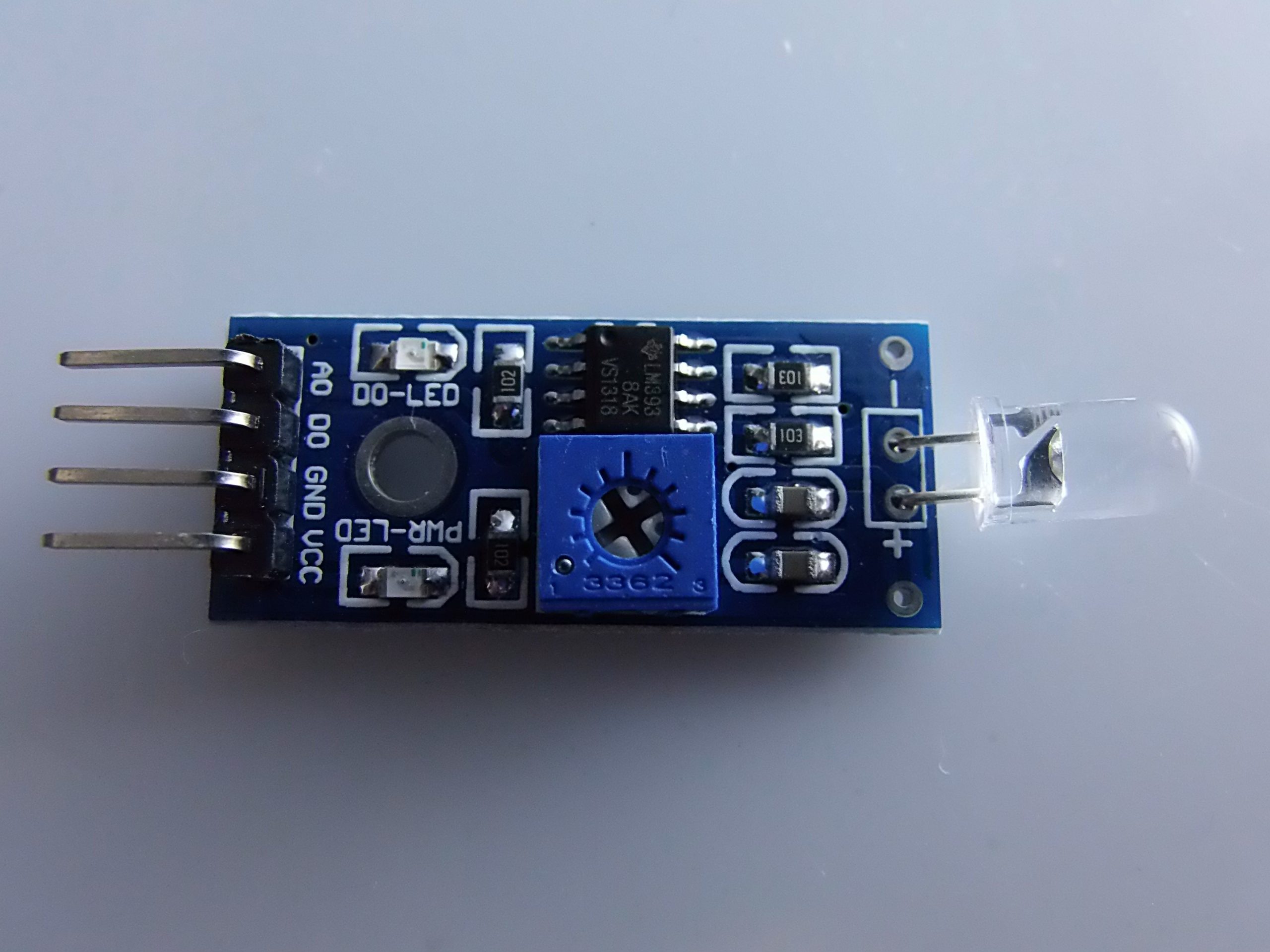
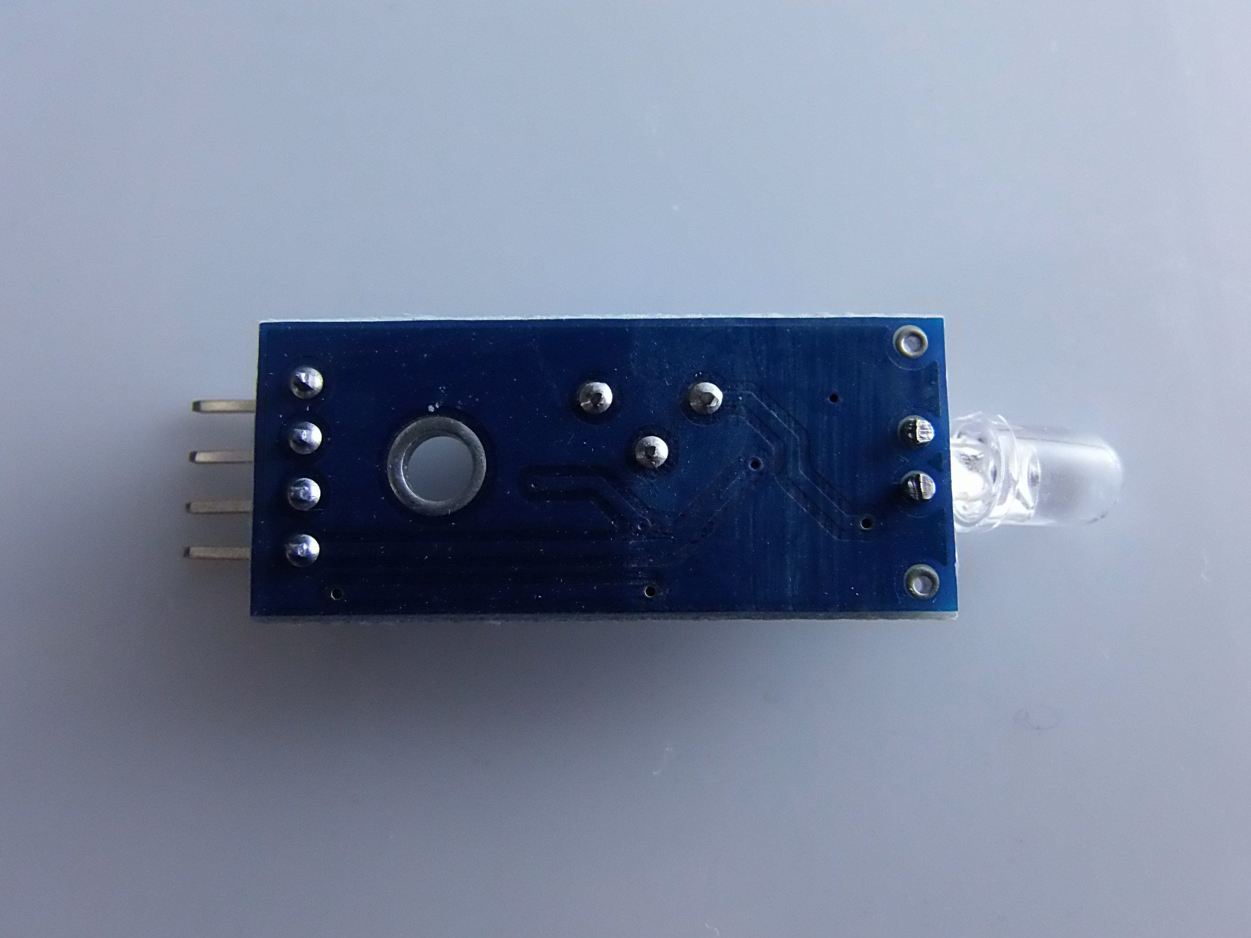
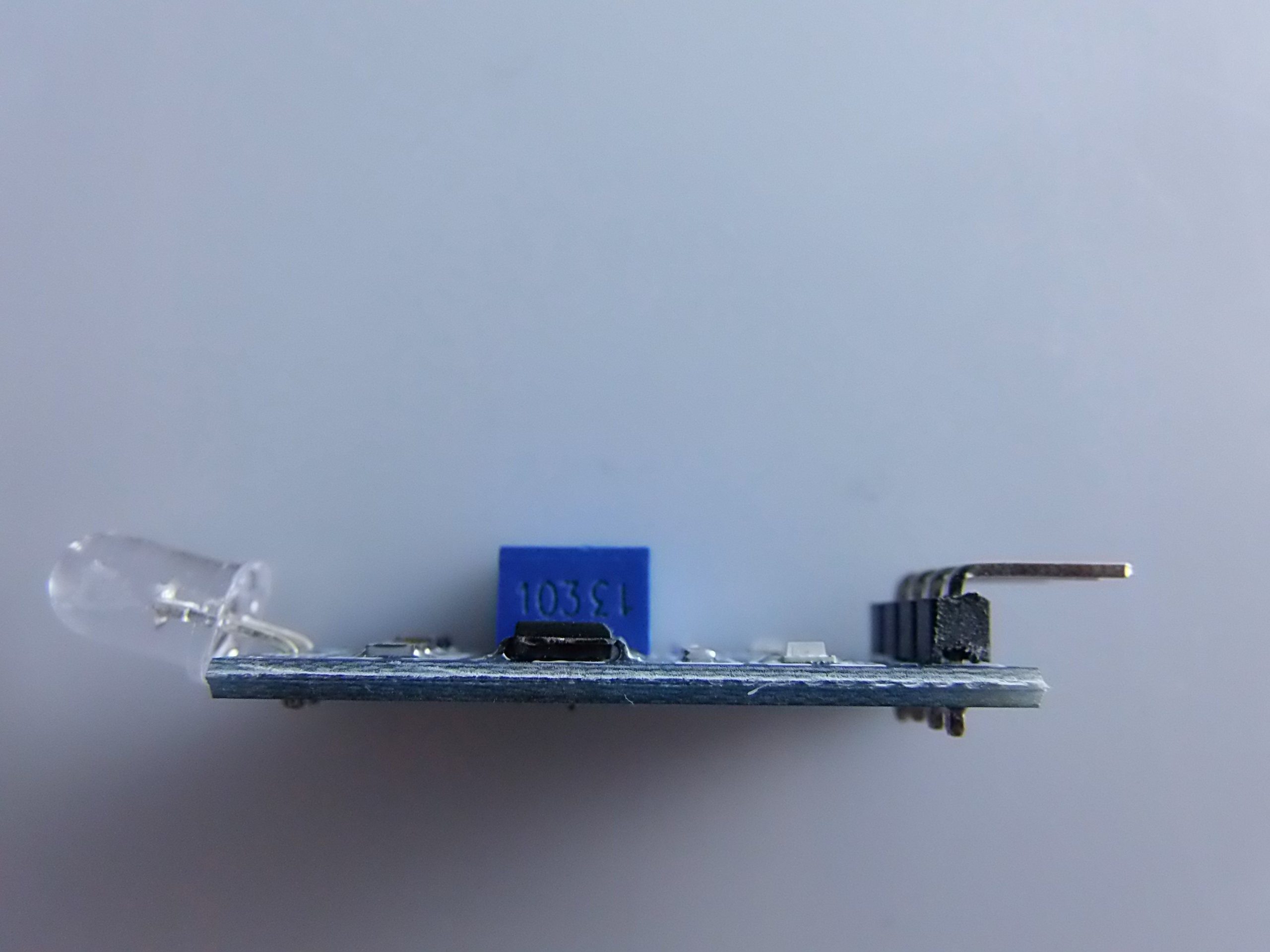
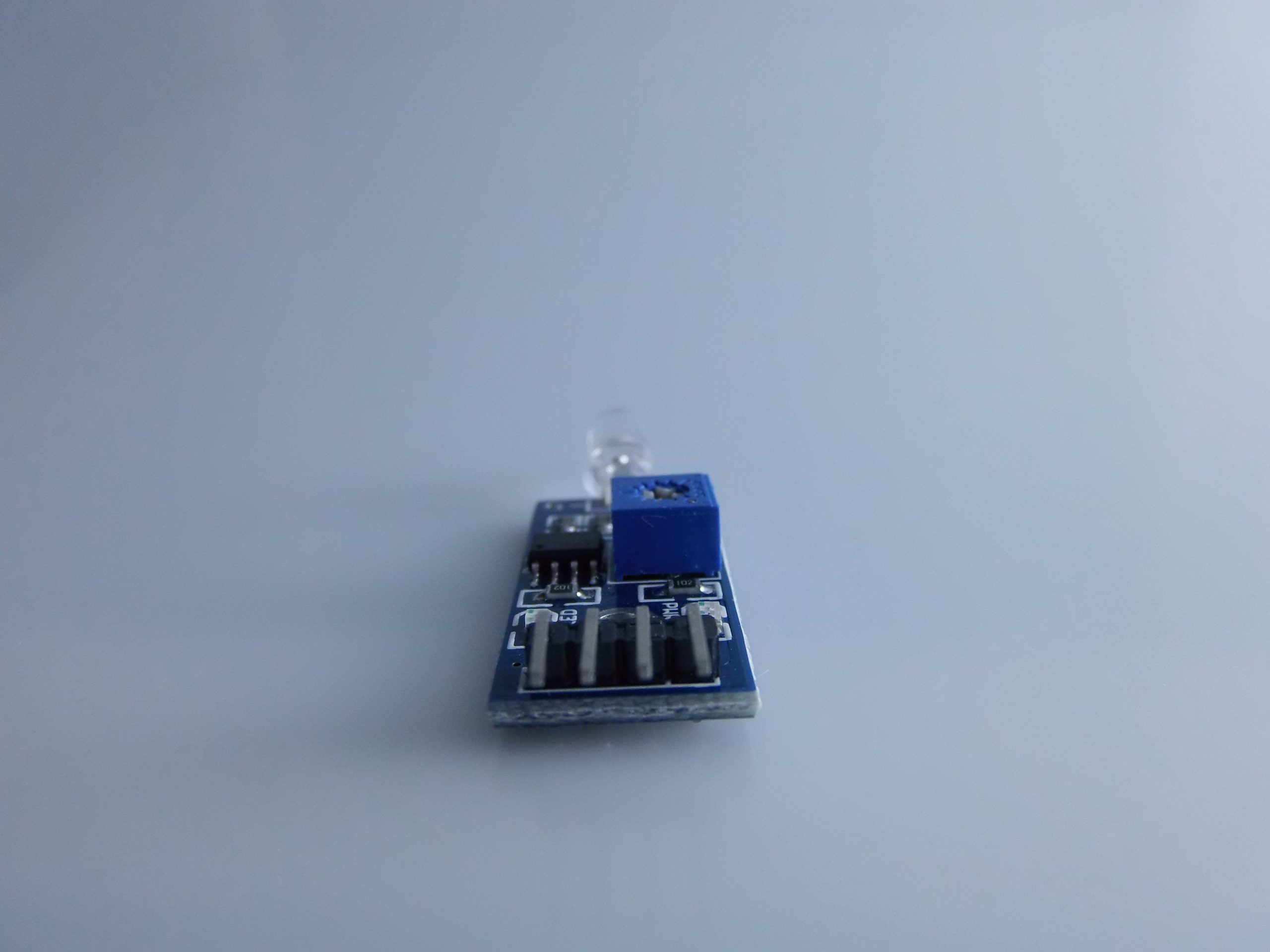
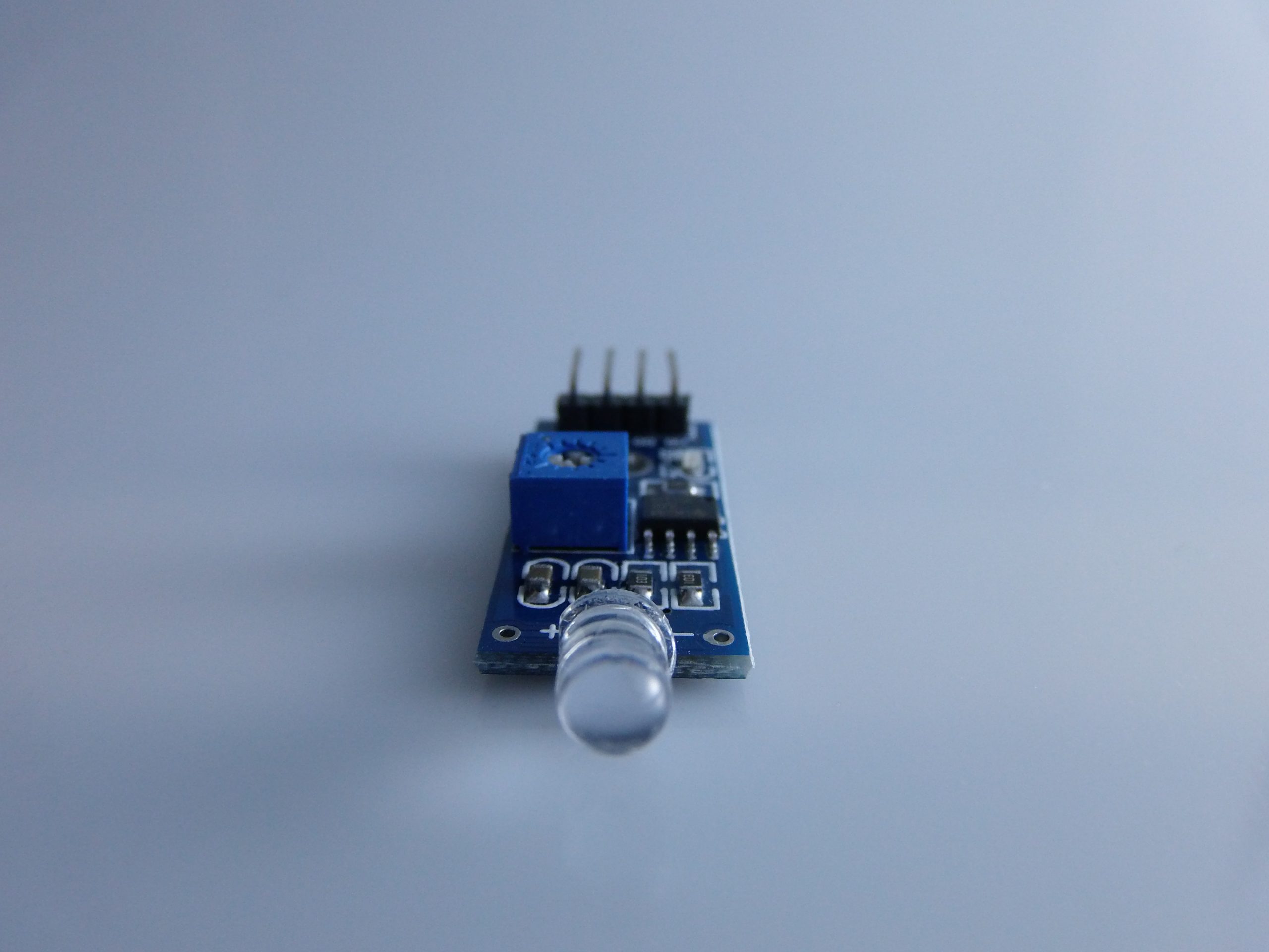
Description
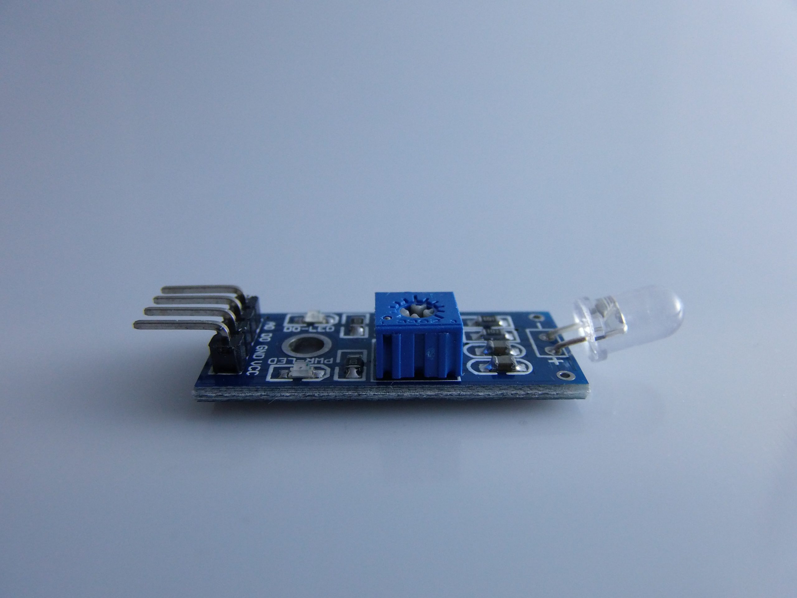
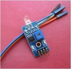
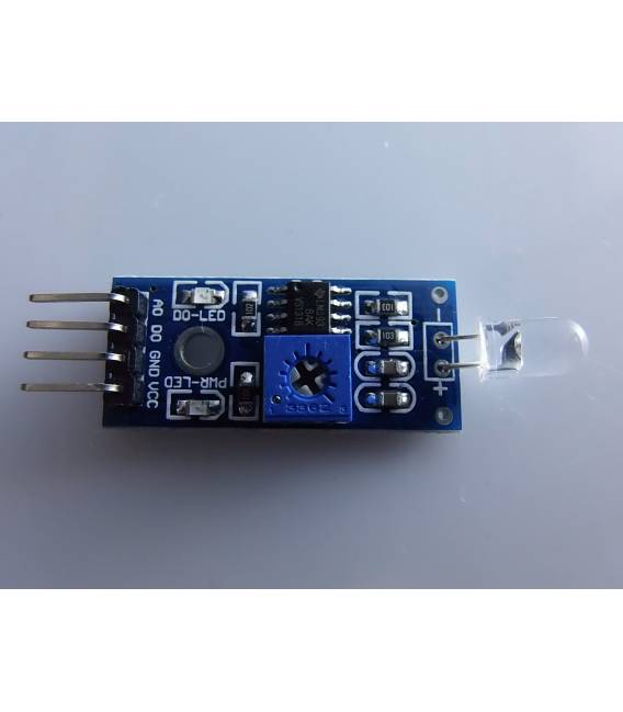
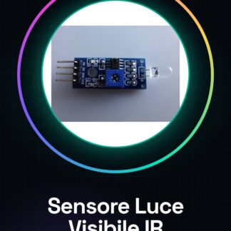
Here is a detailed description of the visible light and infrared (IR) sensor module – photo detector module, a usage guide with Arduino, and some practical programming examples.
🔎 Description of the Visible Light and Infrared (IR) Sensor Module
📦 Common Name:
Visible Light + Infrared (IR) Sensor – Photo Detector Analog/Digital
🧩 Main Components:
- Photodiode or Phototransistor (visible light/IR sensor)
- Op-amp / Comparator (on modules with digital output)
- Trimmer (to adjust the light threshold on digital output)
- LED Indicator (often present for visual feedback)
- Outputs:
- Analog (A0): voltage proportional to the light intensity
- Digital (D0): value HIGH or LOW relative to the set threshold
📐 Technical Specifications:
| Characteristic | Typical Value |
|---|---|
| Operating Voltage | 3.3V – 5V |
| Current Consumption | < 20 mA |
| Output Type | Analog (0-1023 with Arduino) / Digital (0 or 1) |
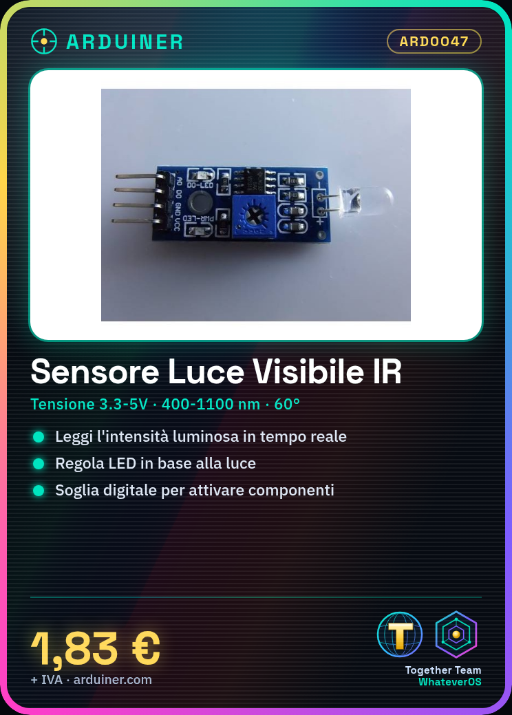
| Spectral Sensitivity | 400 – 1100 nm (visible + IR) |
| Detection Angle | Approximately 60° |
🔌 Module Connection with Arduino
⚙️ Module Pins:
- VCC → 5V (o 3.3V)
- GND → GND
- A0 → Arduino analog pin (e.g., A0)
- D0 → Arduino digital pin (e.g., D2 – optional)
🔧 Connection Diagram (Example with Arduino Uno):
| IR Module | Arduino Uno |
|---|---|
| VCC | 5V |
| GND | GND |
| A0 | A0 |
| D0 (optional) | D2 |
👨💻 Arduino Programming Guide
1. 📈 Read light intensity via analog output (A0)
int pinSensore = A0;

void setup() {
 Serial.begin(9600);
}

void loop() {
 int valoreLuce = analogRead(pinSensore);
 Serial.print("Intensita' luminosa: ");
 Serial.println(valoreLuce); // da 0 (buio) a 1023 (molto luce)
 delay(500);
}
2. 💡 Turn on an LED based on light intensity
int pinSensore = A0;
int pinLED = 9;

void setup() {
 pinMode(pinLED, OUTPUT);
}

void loop() {
 int luce = analogRead(pinSensore);
 if (luce < 300) { // Sotto una soglia (luce debole)
 digitalWrite(pinLED, HIGH);
 } else {
 digitalWrite(pinLED, LOW);
 }
}
3. ⚙️ Read with adjustable digital threshold (D0)
If the module has adjustable digital output via trimmer:
int pinDigital = 2;
int pinLED = 9;

void setup() {
 pinMode(pinDigital, INPUT);
 pinMode(pinLED, OUTPUT);
}

void loop() {
 int stato = digitalRead(pinDigital);
 if (stato == LOW) { // LOW = poco luce (dipende dalla regolazione)
 digitalWrite(pinLED, HIGH);
 } else {
 digitalWrite(pinLED, LOW);
 }
}
🧪 Practical usage examples
✅ Common applications:
- Day/night detection for automatic light switching
- Light intensity control in greenhouses or indoor environments
- Automatic activation of displays or devices based on ambient light
- Passage detection (when combined with an obstacle that blocks the light)
💡 Project ideas:
- Courtesy light: turn on LED only when it’s dark
- Environmental data logger: save light values on SD or send via WiFi
- Optical counter: use the module to count objects that interrupt the light
📌 Tips
- IR modules can be affected by direct sunlight and by IR sources (e.g. TV, remote controls).
- The comparator threshold is adjustable with the trimmer present on the module (turn with a star screwdriver).
- If you use only the analog output, ignore the trimmer and the D0 output.
If you want, I can provide you with a complete project example, including code, Fritzing diagram, and serial graph. Let me know!
|
GENERAL |
MODEL |
Photosensitive diode sensor brightness sensor |
|
MATERIALS |
pcb + components |
|
|
COMPATIBILITY |
ARDUINO |
|
|
ELECTRICAL COMPONENTS |
INPUT VOLTAGE |
5 V |
|
WEIGHT AND DIMENSIONS |
PRODUCT WEIGHT |
7 g |
|
PACKAGE WEIGHT |
0.088 kg |
|
|
PRODUCT DIMENSIONS (L x W x H) |
5 x 2 x 0.5 cm |
|
|
PACKAGE DIMENSIONS (L x W x H) |
10 x 5 x 2 cm |
|
|
PACKAGE CONTENTS |
PACKAGE CONTENTS |
1 x Module |
We have datasheets available for all components, if not present in the product download sheet, please send us a message via the contact form and we will publish it as soon as possible on our website.
Tutorial: How to Use Visible Light IR Sensor
This sensor measures visible light and infrared, ideal for lighting and light control projects.
What you need
- Visible Light IR Sensor
- Arduino or microcontroller
- Power Supply Cable
- Multimeter (optional)
Steps
- 1. Connect the sensor to the microcontroller using the following pins: VCC to 5V, GND to GND, and OUT to a digital pin.
- 2. Install the Wire library for Arduino if necessary.
- 3. Write the code to read values from the sensor.
- 4. Test the sensor using a multimeter if available.
- 5. Configure the sensor for continuous operation.
- 6. Adapt the code to handle the read values.
- 7. Test the sensor with a variable light source.
- 8. Check the datasheet for further details.
Example code
```void loop() { int value = analogRead(A0); Serial.println(value); delay(100);}```Mini project
Create a simple light alarm with the sensor turning on an LED when the light decreases.
Common mistakes
- Do not connect the sensor to VCC 3.3V if the sensor requires 5V.
- Make sure the sensor is properly connected before running the code.
- Do not use a PWM pin to read values from the sensor.
- Do not forget to check the datasheet for further specifications.
Recommended accessories
- LED
- Current limiting resistor
- 5V power supply
- Connection cable
Frequently asked questions
How can I calibrate the sensor?
Check the datasheet for further details.
Can I use the sensor with a 3.3V microcontroller?
Check the datasheet for further details.
Does the sensor work well with all light sources?
The sensor performs better with visible and infrared light.
Reviews
There are no reviews yet.