 EN
 IT Italiano
 ES Español
 FR Français
 DE Deutsch
Description
Tutorial: How to Use TLP781-GB DIP-4 Photo Transistor Optocoupler
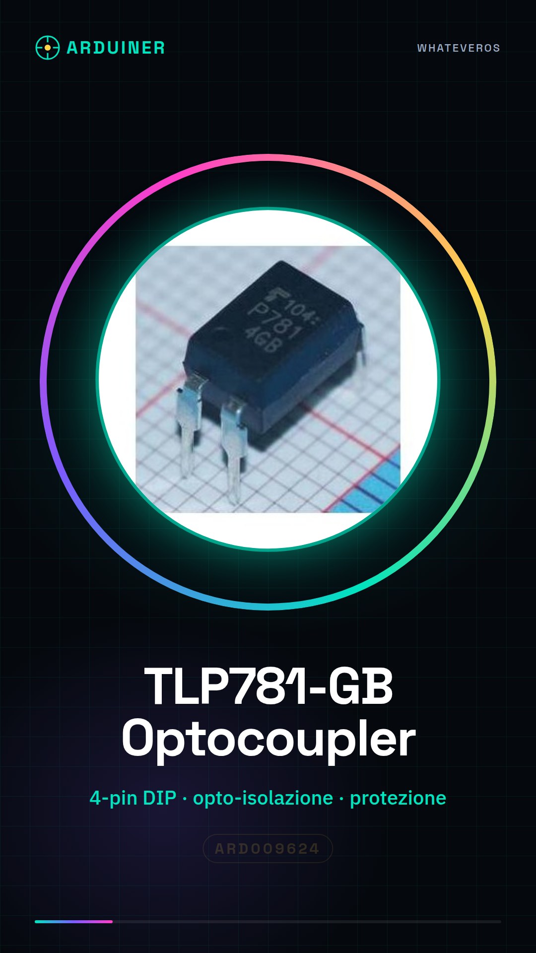
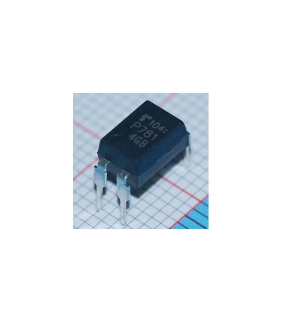
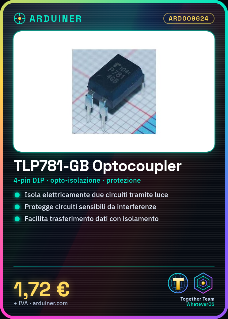
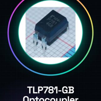
The TLP781-GB is an optocoupler that allows for electrical isolation between two circuits through optical transmission. It is ideal for protecting sensitive circuits from interference or short circuits.
What you need
- circuit isolation
- power protection
- data transfer with isolation
- remote control
Steps
- Check the specifications of the TLP781-GB in the datasheet to understand the pins and required voltage.
- Connect the optocoupler input to a control circuit (for example, an Arduino).
- Connect the output to the other side of the circuit that needs to be isolated.
- Verify proper operation with a multimeter or an oscilloscope.
- Adjust the resistor in series with the LED emitter to control the current flow.
- Test the system under various conditions (for example, by changing the input voltage).
- If necessary, add an RC filter to the output to reduce interference and noise.
- Document the experiment or project for future reference.
Mini project
Create a remote control system for a lamp with isolation between the control circuit and the household electrical network.
Common mistakes
- Use voltages higher than those specified in the datasheet.
- Do not properly verify connections before use.
- Omit the necessary isolation to protect sensitive circuits.
- Ignore the resistor in series with the LED to limit the current.
Recommended accessories
- Variable resistors
- Arduino Uno R3
- Digital multimeter
- DIP 4-pin socket
Frequently asked questions
What is the main function of the TLP781-GB optocoupler?
Its main function is to electrically isolate two circuits by transferring optical signals.
How can I control the current through the LED emitter?
Add a resistor in series with the LED to limit it.
Reviews
There are no reviews yet.