 EN
 IT Italiano
 ES Español
 FR Français
 DE Deutsch
Description
What it is
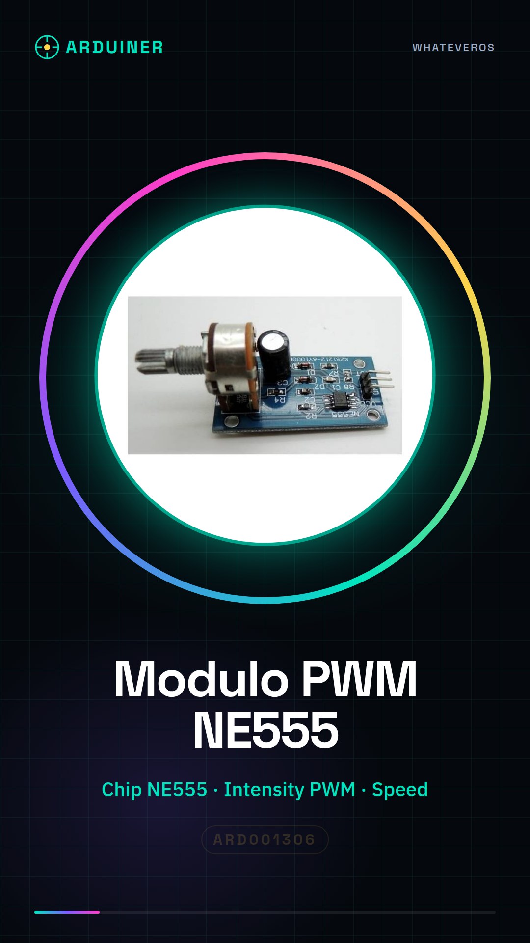
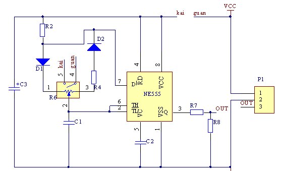
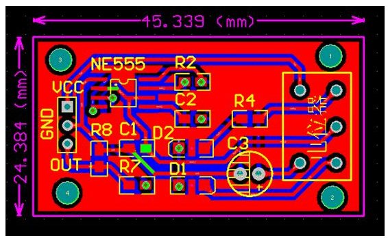
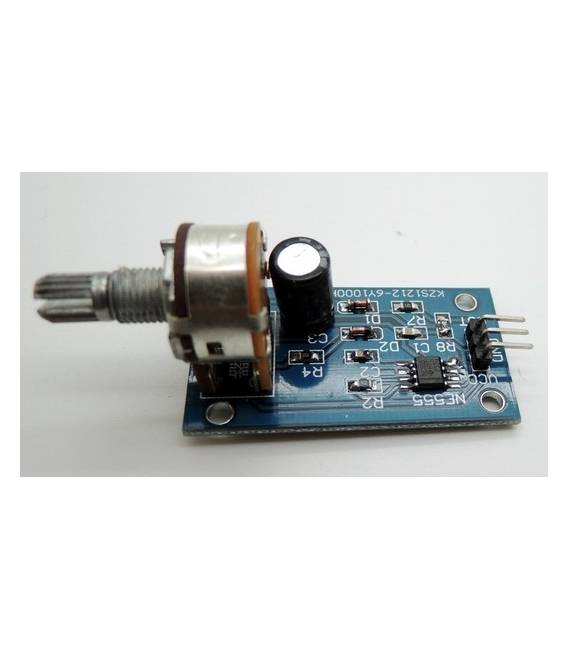
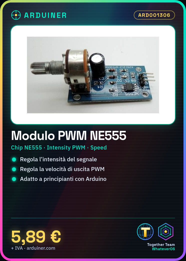
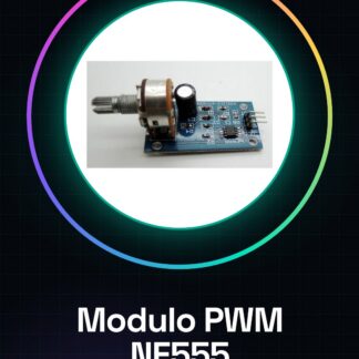
The NE555-based PWM module is an electronic component that allows the regulation of signal intensity and speed in various devices. Using the NE555 chip, this module enables easy implementation of PWM (Pulse Width Modulation) functionality to control motors, LEDs, or other devices that require a PWM output.
Features
- Based on the NE555 chip
- Regulation of signal intensity and speed
- Ideally suited for Arduino projects
What it is for
This module is ideal for beginners who want to control motors, LEDs, or any other device that requires a PWM output. You can use it to create simple LED dimmers by adjusting the brightness through a button connected to a digital pin on an Arduino.
Tutorial: How to use NE555 PWM Module
The NE555-based PWM module allows you to adjust the signal intensity and speed in various electronic devices. Ideal for beginners who want to control motors, LEDs, or any other device that requires a PWM output.
What you need
- Arduino Uno
- 3-pin header connections
- Various LEDs
- Resistors
Steps
- Connect the NE555 module to pin 9 of the Arduino using a 3-pin header connection.
- Connect an LED to ground and a resistor to the PWM output pin of the NE555 module.
- Check the required power supply voltage on the datasheet and ensure the module is adequately powered.
- Write the Arduino sketch to adjust the LED intensity via PWM.
- Compile and upload the sketch to your Arduino.
- Obtain the desired PWM signal frequency by modifying the values in the code.
- Test the PWM module by connecting it to a motor or other compatible PWM output devices.
- Adjust the intensity and speed of the device according to your needs.
Example code
void setup() {
  pinMode(9, OUTPUT);
}

void loop() {
  analogWrite(9, 128); // Regolare il valore da 0 a 255 per variare l'intensità PWM.
}
Mini project
Create a simple LED dimmer that allows you to adjust the brightness of the LED through a button connected to a digital pin.
Common mistakes
- Do not check the required power supply voltage for the PWM module.
- Enter invalid values in the Arduino code for PWM intensity.
- Connect the device without testing it first with an LED or a resistor.
- Modify the PWM signal parameters without understanding their implications on the connected device.
Recommended accessories
- 3-pin header connections
- Variable resistors
- Buttons
- DC Motors
Frequently asked questions
What is the minimum and maximum frequency I can get with this PWM module?
Check the datasheet of the NE555 chip to determine the available frequencies.
Can I use this PWM module with other microcontrollers besides Arduino?
Yes, but make sure the output pin is compatible with the PWM output of your microcontroller.
How can I control the frequency and amplitude of the PWM signal?
Modify the values in the Arduino code or add external components such as capacitors and resistors to adjust these characteristics.
Reviews
There are no reviews yet.