 EN
 IT Italiano
 ES Español
 FR Français
 DE Deutsch
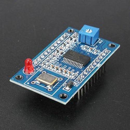
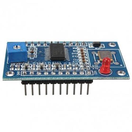
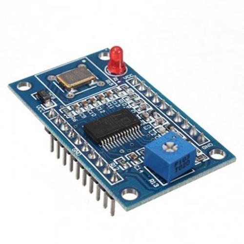
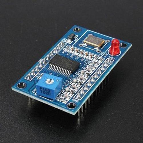
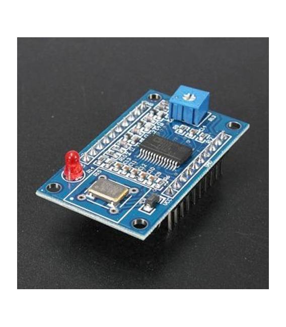
Description
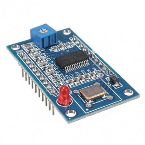
📡 AD9850 Direct Digital Synthesis (DDS) Signal Generator Module – Complete Description and Guide for Use with Arduino
🔧 General Description of the AD9850 DDS Module
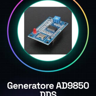
The AD9850 DDS Module (Direct Digital Synthesis) is a variable frequency sine, square, and triangular wave signal generator , widely used in hobbyist, amateur radio, and educational settings for generating test signals and development., widely used in hobbyist, amateur radio, and educational settings for generating test signals and development.
✅ Main Chip:
- Analog Devices AD9850 Operating Voltage:
- 5V DC Output Frequency:
- from 0 Hz up to approximately 40 MHz (sinusoidal recommended up to 20 MHz for signal purity) (recommended sine wave up to 20 MHz for signal purity)
- 32-bit tuning word (very precise frequency) 32-bit tuning word (very precise frequency)
- Control Interface: Serial (parallel available but less used with Arduino)
- Output Signals:
- Filtered sine wave output
- Square wave output (TTL, up to 5Vpp)
- Connectors: Standard 2.54 mm header pins
- Integrated Components:
- 125 MHz quartz oscillator
- Low-pass filter for sine wave output
- Operational amplifier for direct drive
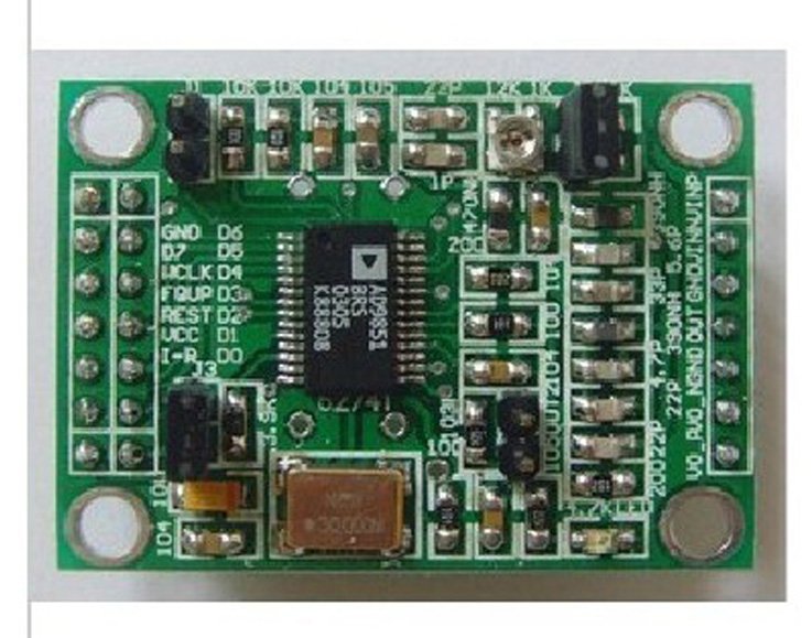
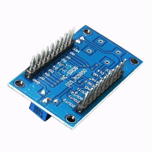
⚙️ AD9850 Module Pinout
| PIN | Description |
|---|---|
| VCC | 5V Power Supply |
| GND | Ground |
| D7 – D0 | Parallel data bus (not used in serial) |
| W_CLK | Write clock |
| FQ_UD | Frequency update (latch) |
| DATA | Serial data |
| RESET | Chip reset |
| SQ_OUT | Square wave output |
| SIN_OUT | Filtered sine wave output |
🧠 How Does the DDS (Direct Digital Synthesis) Work?
The principle of DDS involves generating a sine wave digitally through a phase accumulator, a ROM containing sine values, and a DAC. This allows for precise and rapid variation of the output frequency with excellent stability.
🔌 Connecting the AD9850 Module to Arduino
✨ Arduino UNO Connection Diagram:
| Arduino | AD9850 Module |
|---|---|
| 5V | VCC |
| GND | GND |
| D2 | RESET |
| D3 | DATA |
| D4 | W_CLK |
| D5 | FQ_UD |
🧪 Example Code for Arduino
You can easily control the AD9850 module with a dedicated library or directly through code. Here is a basic example without a library to generate a 1 MHz signal:, for generating a signal at 1 MHz:
#define W_CLK 4 // Pin W_CLK
#define FQ_UD 5 // Pin FQ_UD
#define DATA 3 // Pin DATA
#define RESET 2 // Pin RESET

void setup() {
 pinMode(W_CLK, OUTPUT);
 pinMode(FQ_UD, OUTPUT);
 pinMode(DATA, OUTPUT);
 pinMode(RESET, OUTPUT);

 // Reset iniziale del modulo
 digitalWrite(RESET, LOW);
 digitalWrite(W_CLK, LOW);
 digitalWrite(FQ_UD, LOW);
 digitalWrite(RESET, HIGH);
 digitalWrite(RESET, LOW);

 setFrequency(1000000); // 1 MHz
}

void loop() {
 // Nessuna azione continua necessaria
}

void pulse(int pin) {
 digitalWrite(pin, HIGH);
 delayMicroseconds(1);
 digitalWrite(pin, LOW);
}

void setFrequency(unsigned long frequency) {
 // Costante derivata da 2^32 / 125 MHz (frequenza dell’oscillatore)
 double tuningWord = (frequency * pow(2, 32)) / 125000000.0;
 unsigned long freqWord = (unsigned long)(tuningWord);

 // Invia la word a 32 bit (LSB first)
 for (int i = 0; i < 4; i++) {
 shiftOut(DATA, W_CLK, LSBFIRST, freqWord >> (8 * i));
 }

 shiftOut(DATA, W_CLK, LSBFIRST, 0x00); // Ultimo byte: controllo fase

 // Aggiorna il DDS
 pulse(FQ_UD);
}
📚 🔄 Advanced Guide: What You Can Do
🔄 Dynamically Change the Frequency
You can write a function that reads values from a potentiometer or serial and updates the frequency in real-time.
🎛️ Possible Modulations
- FSK: by rapidly changing the frequency
- PSK: by changing the phase
- AM (limited): with external circuitry
- Sweep: frequency sweep generation for frequency response testing
📈 Output to Oscilloscope
Connect SIN_OUT directly to an oscilloscope or an amplifier. The signal can be weak for high impedance loads.
📦 Alternative Libraries (optional)
To facilitate usage, you can use an Arduino library such as:
DDS_AD9850
Installable from GitHub: https://github.com/F4GOJ/AD9850
Example with library:
#include <AD9850SPI.h>

AD9850SPI dds(5, 4, 3); // FQ_UD, W_CLK, DATA

void setup() {
 dds.reset();
 dds.setFrequency(2000000); // 2 MHz
}

void loop() {
 // puoi aggiornare dinamicamente se vuoi
}
🛠️ Usage Tips
- Filter the power supply well to avoid noise
- Avoid very high frequencies if you want a clean sinusoidal signal
- For generating triangular waves, additional filtering is required (not natively supported)
- Use
SQ_OUTif you need a precise TTL signal
🧾 Typical Applications
- Test generator for amplifiers
- RF Signal Generation for Ham Radio
- Frequency Response Analysis
- Interface with Mixer for SDR Experiments
- Signal Generator for Musical Instruments
Great! I propose a complete guide to build a multifunction AD9850 signal generator with Arduino, integrating all three functions you mentioned:
🎛️ PROJECT: Multifunction AD9850 Signal Generator
🔹 Features:
- Frequency control via rotary encoder
- OLED display visualization
- Optional control via Bluetooth / serial (smartphone or PC)
🧰 Required Components:
| Component | Quantity | Notes |
|---|---|---|
| Arduino UNO/Nano | 1 | Mega is also compatible |
| AD9850 DDS Module | 1 | Frequency up to 40 MHz |
| Rotary Encoder with Push Button | 1 | Model EC11 |
| 128×64 I2C OLED Display (SSD1306) | 1 | 0.96″ recommended |
| Optional Bluetooth HC-05/HC-06 Module | 1 | For remote control |
| Optional buttons | 1-2 | For reset/sweep |
| Breadboard or PCB | 1 | and jumper wires |
⚙️ Connection Diagram
✳️ AD9850 Connection
| AD9850 | Arduino |
|---|---|
| VCC | 5V |
| GND | GND |
| W_CLK | D4 |
| FQ_UD | D5 |
| DATA | D3 |
| RESET | D2 |
| SIN_OUT | Oscilloscope, amplifier etc. |
🔄 Rotary Encoder
| Encoder | Arduino |
|---|---|
| CLK | D6 |
| DT | D7 |
| SW (button) | D8 |
📺 OLED Display (SSD1306 I2C)
| OLED | Arduino |
|---|---|
| VCC | 3.3V o 5V |
| GND | GND |
| SDA | A4 |
| SCL | A5 |
📡 HC-05 Bluetooth (optional)
| HC-05 | Arduino |
|---|---|
| VCC | 5V |
| GND | GND |
| TX | RX (D0) |
| RX | TX (D1, with voltage divider!) |
🧪 Arduino Code (Basic functions integrated)
📦 Required Libraries:
U8g2libfor OLEDRotaryEncodermanual controlSoftwareSerialvia Bluetooth (if used)
Install from Library Manager:
U8g2 by olikraus
✅ Simplified code:
#include <U8g2lib.h>
#include <Wire.h>

#define W_CLK 4
#define FQ_UD 5
#define DATA 3
#define RESET 2

#define ENCODER_CLK 6
#define ENCODER_DT 7
#define ENCODER_SW 8

unsigned long frequency = 1000000; // 1 MHz di default
long step = 1000; // Passo iniziale (1 kHz)

// OLED: U8G2_SSD1306_128X64_NONAME_F_SW_I2C(RST, SCL, SDA)
U8G2_SSD1306_128X64_NONAME_F_SW_I2C u8g2(U8G2_R0, /* clock=*/ A5, /* data=*/ A4, /* reset=*/ U8X8_PIN_NONE);

void pulse(int pin) {
 digitalWrite(pin, HIGH);
 delayMicroseconds(1);
 digitalWrite(pin, LOW);
}

void setFrequency(unsigned long freq) {
 double tuningWord = (freq * pow(2, 32)) / 125000000.0;
 unsigned long freqWord = (unsigned long)(tuningWord);

 for (int i = 0; i < 4; i++) {
 shiftOut(DATA, W_CLK, LSBFIRST, freqWord >> (8 * i));
 }
 shiftOut(DATA, W_CLK, LSBFIRST, 0x00); // Phase = 0
 pulse(FQ_UD);
}

void setup() {
 pinMode(W_CLK, OUTPUT);
 pinMode(FQ_UD, OUTPUT);
 pinMode(DATA, OUTPUT);
 pinMode(RESET, OUTPUT);

 digitalWrite(RESET, LOW);
 digitalWrite(W_CLK, LOW);
 digitalWrite(FQ_UD, LOW);
 digitalWrite(RESET, HIGH);
 digitalWrite(RESET, LOW);

 pinMode(ENCODER_CLK, INPUT);
 pinMode(ENCODER_DT, INPUT);
 pinMode(ENCODER_SW, INPUT_PULLUP);

 u8g2.begin();
 setFrequency(frequency);
 displayFreq();
}

int lastCLK = HIGH;

void loop() {
 int clk = digitalRead(ENCODER_CLK);
 int dt = digitalRead(ENCODER_DT);

 if (clk != lastCLK && clk == LOW) {
 if (dt == HIGH) {
 frequency += step;
 } else {
 frequency = max(frequency - step, step);
 }
 setFrequency(frequency);
 displayFreq();
 }
 lastCLK = clk;

 if (digitalRead(ENCODER_SW) == LOW) {
 step = (step == 1000) ? 100000 : 1000;
 delay(300); // debounce
 }
}

void displayFreq() {
 u8g2.clearBuffer();
 u8g2.setFont(u8g2_font_ncenB08_tr);
 u8g2.setCursor(0, 20);
 u8g2.print("Freq:");
 u8g2.setCursor(0, 40);
 u8g2.setFont(u8g2_font_fub20_tr);
 u8g2.print(frequency / 1000.0, 3);
 u8g2.print(" kHz");
 u8g2.sendBuffer();
}
📡 Control via Bluetooth / Serial Monitor
Add this function to receive a serial command of the type: F2000000 → change frequency to 2 MHz
Added to loop():
if (Serial.available()) {
 String input = Serial.readStringUntil('n');
 if (input.startsWith("F")) {
 unsigned long newFreq = input.substring(1).toInt();
 if (newFreq > 0 && newFreq < 40000000) {
 frequency = newFreq;
 setFrequency(frequency);
 displayFreq();
 }
 }
}
🔄 Automatic Sweep (optional)
Add a function to sweep between two frequencies:
void sweep(unsigned long fStart, unsigned long fStop, int delayMs) {
 for (unsigned long f = fStart; f <= fStop; f += step) {
 setFrequency(f);
 displayFreq();
 delay(delayMs);
 }
}
🧾 Possible Expansions
- Add an OLED menu to choose waveform (square/sine)
- Save last frequencies in EEPROM
- USB-C port with isolation for bench instruments
- Android Bluetooth app to control frequency
✅ Conclusion
You now have a fully controllable DDS platform:
- Manually with encoder
- Graphically via display
- Remotely via smartphone or PC
|
GENERAL INFORMATION |
MODEL |
AD9850 Module DDS Signal Generator |
|
MATERIALS |
pcb + components |
|
|
COMPATIBILITY |
ARDUINO |
|
|
ELECTRICAL COMPONENTS |
INPUT VOLTAGE |
3,3 – 5 V |
|
WEIGHT AND DIMENSIONS |
PRODUCT WEIGHT |
15g |
|
PACKAGE WEIGHT |
0.55 kg |
|
|
PRODUCT DIMENSIONS (L x W x H) |
4.6 x 2.5 x 2 |
|
|
PACKAGE DIMENSIONS (L x W x H) |
10 x 5 x 5 cm |
|
|
CONTENTS OF THE PACKAGE |
CONTENTS OF THE PACKAGE |
1 x Module |
We have datasheets available for all components, should it not be present in the product download sheet, please send us a message through the contact form and we will publish it as soon as possible on our website.
Tutorial: How to Use AD9850 DDS Signal Generator
The AD9850 DDS module is a direct digital synthesizer signal generator ideal for makers who want to create and modify precise sinusoidal signals. This component is particularly useful for radio communication projects, testing, and measurement.
What you need
- Arduino Uno or compatible
- USB A-B cable
- Jumper Connections
- Arduino IDE Software
Steps
- Connect the AD9850 DDS module to the digital pins of the Arduino (check the datasheet for specific pins)
- Download and install the DDS library in the Arduino IDE software
- Load the example sketch provided with the library onto Arduino
- Modify the sketch settings based on your needs (frequency, signal amplitude)
- Check the module’s functionality by monitoring the output on the Serial Monitor of the Arduino IDE
- If necessary, adjust the signal parameters to optimize project performance
Example code
// Includere la libreria DDS
#include <DDS.h>

// Definire l'oggetto DDS e collegarlo ai PIN dell'Arduino
DDS dds(10, 9);

void setup() {
 Serial.begin(9600);
}

void loop() {
 // Impostare la frequenza del segnale (verifica sul datasheet per il range)
 dds.setFrequency(1000);
}
Mini project
Create an AM signal generator with AD9850 DDS: modulate an audio signal onto a carrier frequency set by the DDS module
Common mistakes
- Set the signal frequency outside the allowed range (check the datasheet)
- Fail to correctly load the example sketch into the Arduino IDE software
- Omit the installation of the required DDS library for the module to function
- Fail to verify the physical connection between AD9850 and Arduino
Recommended accessories
- 16×2 LCD Module
- Audio Amplifier
- Reception Antenna
- Voltage Regulator LM317
Frequently asked questions
What is the minimum and maximum frequency I can generate with the AD9850 DDS?
The frequency varies based on the clock provided (check the datasheet)
How can I control the AD9850 DDS module without using Arduino?
You can use a compatible microcontroller or logic circuit to send commands to the module
Reviews
There are no reviews yet.