 EN
 IT Italiano
 ES Español
 FR Français
 DE Deutsch
Description
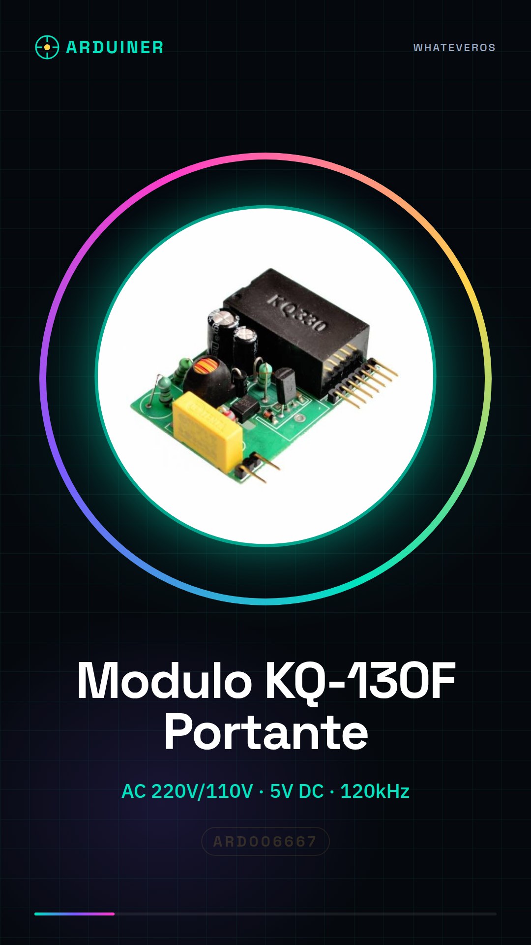
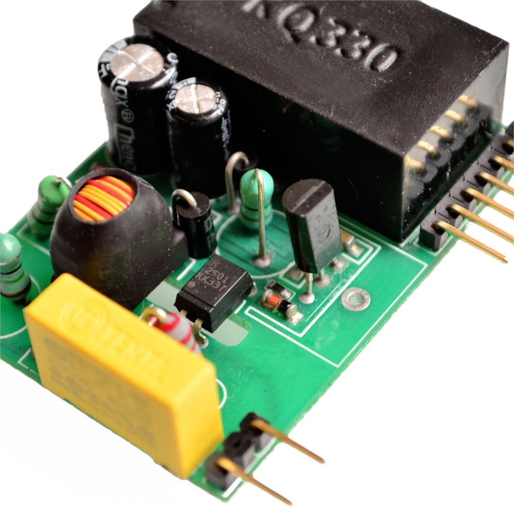
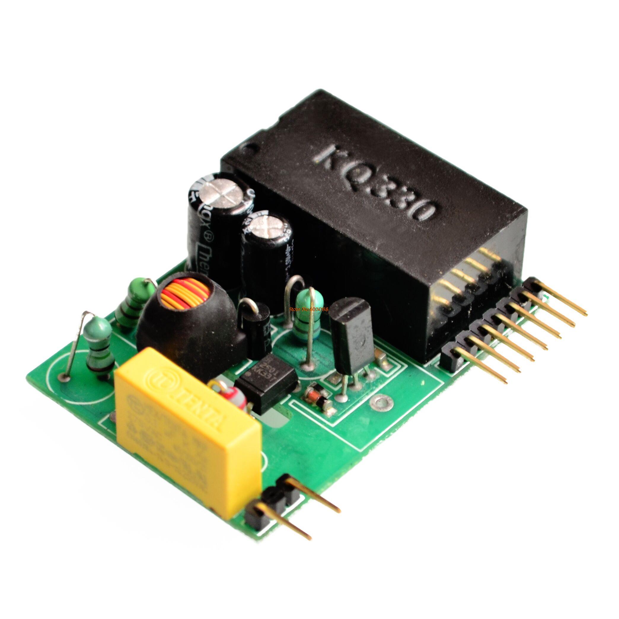
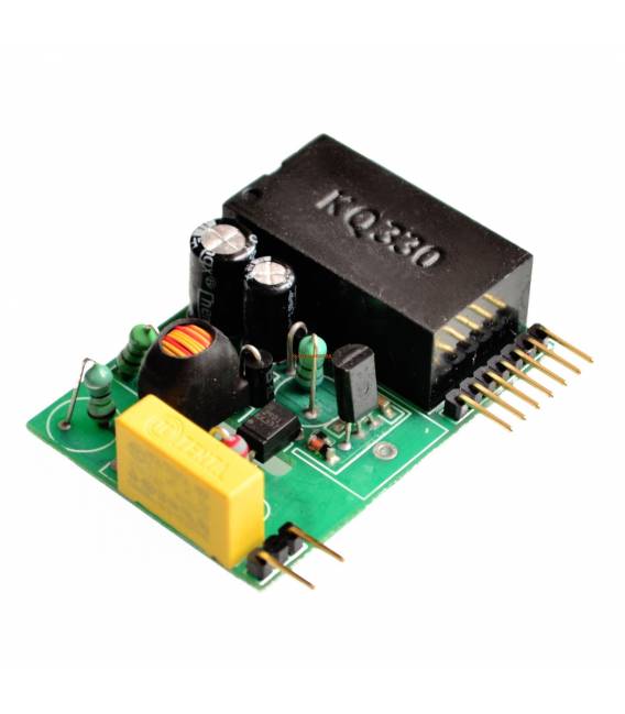
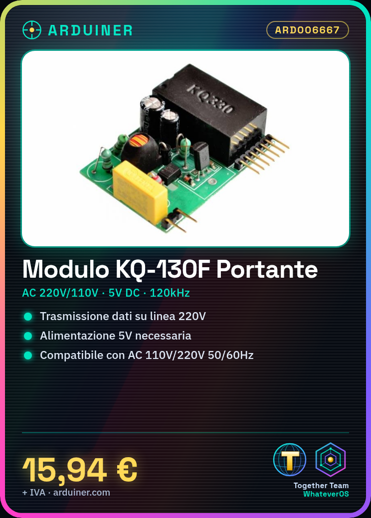
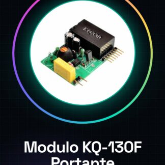
KQ-130F Power Line Carrier Module
Features:
The KQ-130F is designed for AC 220V / 110V, 50Hz / 60Hz strong design interference vector-based carrier transmission scheme with zero transmission effect on electric power transmission, transmission distance and so on.
The KQ-130F carrier module does not require peripheral devices, as long as a 5V power supply can be used. It has independent power supply pins, if the user needs to transmit two paths, two parallel 5V pins are required.
The KQ-130F operation includes a carrier driver, coupling, filtering, lightning protection, and many other complex peripheral circuits.
Users only need to provide a single 5V power supply, after connecting the two signal lines (TX, RX) to the microcontroller, direct connection to 220V (regardless of FireWire, the neutral line), carrier waves are transmitted through a completely transparent manner for data transmission and reception between the two AC modules.
The KQ-130F series of zero carrier data transceiver modules are based on the true meaning of zero modulation and carrier demodulation. It features anti-interference capabilities and transmission distance.
Description:
Operating frequency: 120 ~ 135KHz.
Transmission interface speed: 9600 bps. Current transmission speed: 100bps.
Reception sensitivity: 1mV.
Band rejection: 60dB.
Bandwidth: 10KHz.
Insulation resistance: 500V 500M .
Power supply: DC + 5V when receiving: 11mA, transmitting: 230mA.
industrial frequency voltage withstand: proof between GND 3000V 1min no damage, no leakage current.
Anti-surge: one internal TVS panel protection for tube from PCB layout selection to component selection are designed to function in a wide range of temperatures, high pressure, high pressure resistance.
Operating temperature: -25 ~ 70 Humidity 90%.
Dimensions: 53 * 38 * 17mm (L * W * H).
Weight: 28g / 0.97 oz
Maximum continuous transmission length 252 bytes sent a continuous length from 1-252 defined by the user, the module does not send redundant data.
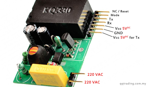
PIN Descriptions:
1P-AC: 220V AC FireWire (or neutral).
2P-AC: 220V AC to zero line (or FireWire).
3p + 5V: + 5V power supply send (260mA), if the received data can be left alone to reduce power consumption.
4P-GND: digital circuit ground.
5P- + 5V: + 5V power supply, 11mA.
6P-RX: TTL level, carrier data, MCU TXD.
7P-TX: TTL level, data support, MCU RXD.
8P-MODE: mode selection, float high at 5V, low at ground.
9P-NC / RST: reset pin (active low) when switching modes is rarely used in the workshop. This function is not necessary, the pin must be left unconnected.
KQ-130F module suitable for street lighting, smart home, fire safety, building control and other applications requiring power lines to carry data. Transmission distance up to 1.5 km.
Tutorial: How to use Floating Modem Module KQ-130F
The KQ-130F modem carrier module is ideal for anyone who wants to send data and receive messages through a GPRS connection. It is particularly useful for IoT projects or remote monitoring.
What you need
- Arduino Uno
- USB-A to B cable
- Arduino IDE software installed
Steps
- Connect the KQ-130F module to the Arduino Uno via the TX and RX connectors.
- Install the GPRS Shield Library in the Arduino IDE software.
- Upload a sample sketch provided by the library to your Arduino.
- Verify that the KQ-130F module is recognized by the computer through the Arduino IDE serial monitor.
- Configure the module settings, such as the SIM card and GPRS network, following the documentation provided by the manufacturer.
- Send a test message or receive data through a GPRS data connection.
- Refer to the datasheet for detailed information on module configuration.
- Test the stability of the connection and resolve any issues.
Example code
/*
* Esempio di codice per inviare un messaggio SMS
*/
#include <GPRS_Shield.h>
GPRS gprs;
void setup() {
 Serial.begin(9600);
}
void loop() {
 if (gprs.sendSMS("NumeroTelefonoDestinatario", "MessaggioTestuale")) {
 Serial.println("Messaggio inviato");
 } else {
 Serial.println("Errore nell'invio del messaggio");
 }
}
Mini project
Create a remote monitoring system that sends the user an SMS notification when a certain temperature is exceeded.
Common mistakes
- Incorrect TX and RX connection between Arduino and KQ-130F module
- Module settings configured incorrectly
- GPRS data connection problems
- Library installed but not recognized by the Arduino IDE software
Recommended accessories
- External antenna to improve cellular signal reception
- Portable power supply battery for mobile projects
- LCD or LED display to show real-time data
- Temperature and humidity sensors integrated with the KQ-130F module
Frequently asked questions
What is the difference between GPRS and GSM?
GPRS focuses on data transmission, while GSM includes voice calls.
How can I test if the KQ-130F module is functioning correctly?
Send an SMS message or verify data reception via GPRS.
Reviews
There are no reviews yet.