 EN
 IT Italiano
 ES Español
 FR Français
 DE Deutsch
Description
What it is
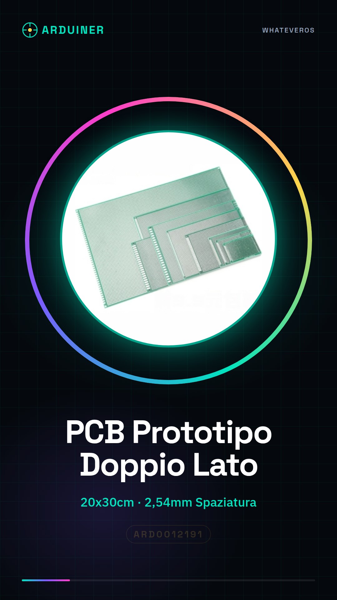
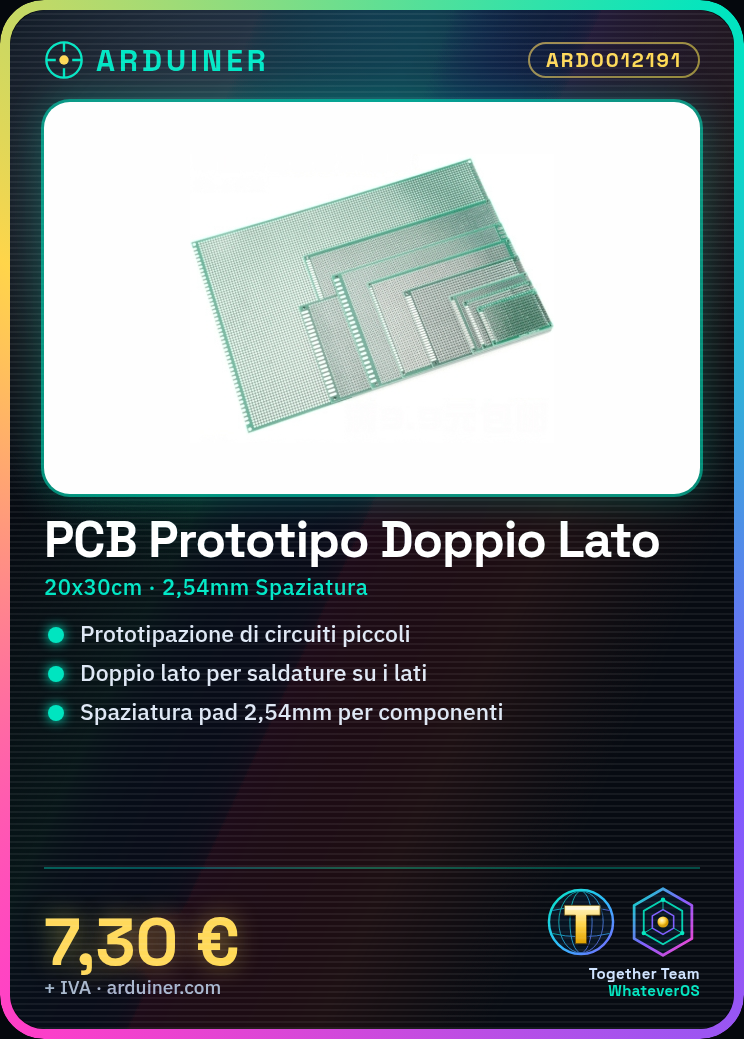
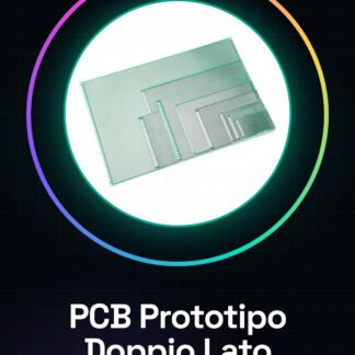
The Double-Sided Prototype PCB 20x30cm 2.54mm is a universal printed circuit board ideal for Arduino users and electronics experts who want to create prototypes and small-sized projects. This PCB is perfect for both beginners and experts looking for a flexible support suitable for various types of electronic components.
Features
- Dimensions: 20x30cm
- Pad spacing: 2.54mm
- Double-sided
What it is for
This PCB is ideal for creating simple circuit prototypes, for example with an LED and a resistor. It is compatible with a wide range of electronic components, including those used in Arduino and ESP projects. Typical uses include the creation of lighting circuits, component testing, and the development of small-sized prototypes.
Tutorial: How to use Double-Sided Prototype PCB 20x30cm 2.54mm
The Double-Sided Prototype PCB is a universal printed circuit board ideal for makers and electronics enthusiasts who want to create prototypes and small projects. This PCB is perfect for beginners and experts looking for a flexible support suitable for various types of electronic components.
What you need
- Double-Sided Prototype PCB 20x30cm 2.54mm
- Wide Head Pins
- Scotch or Insulating Tape
- Soldering Iron
- Soldered Rivets
- Cutting Pliers
Steps
- Before starting, clean the PCB with a dry cloth to remove any impurities.
- Place the components on a part of the PCB and use the insulating tape to secure them in place.
- Use the soldering iron to solder the components to the pins of the PCB. Check the temperature of the soldering iron before starting.
- If necessary, use soldered rivets to connect the various levels of the PCB.
- Check the soldering and correct any errors.
- If you want to print a custom design, use a laser cutter or a CNC plotter to etch the PCB.
- Test the PCB with a multimeter to ensure that all connections are correct.
- If everything is in order, mount the PCB in the project and test it.
Mini project
Create a simple lighting circuit prototype with an LED and a resistor. Connect the LED to the PCB and solder it to create a functioning circuit.
Common mistakes
- Insufficient or excessive soldering
- Incorrectly positioned components
- Incorrect connectivity between PCB layers
- Use of components incompatible with the PCB
Recommended accessories
- Wide pin heads
- Soldering iron
- Solder pins
- Multimeter
Frequently asked questions
How can I clean the PCB?
Use a dry cloth to remove dust and impurities.
Which components can I connect to the PCB?
You can connect any component that fits the PCB holes.
How can I check the soldering?
Use a multimeter to check the continuity of the connections.
Reviews
There are no reviews yet.