 EN
 IT Italiano
 ES Español
 FR Français
 DE Deutsch


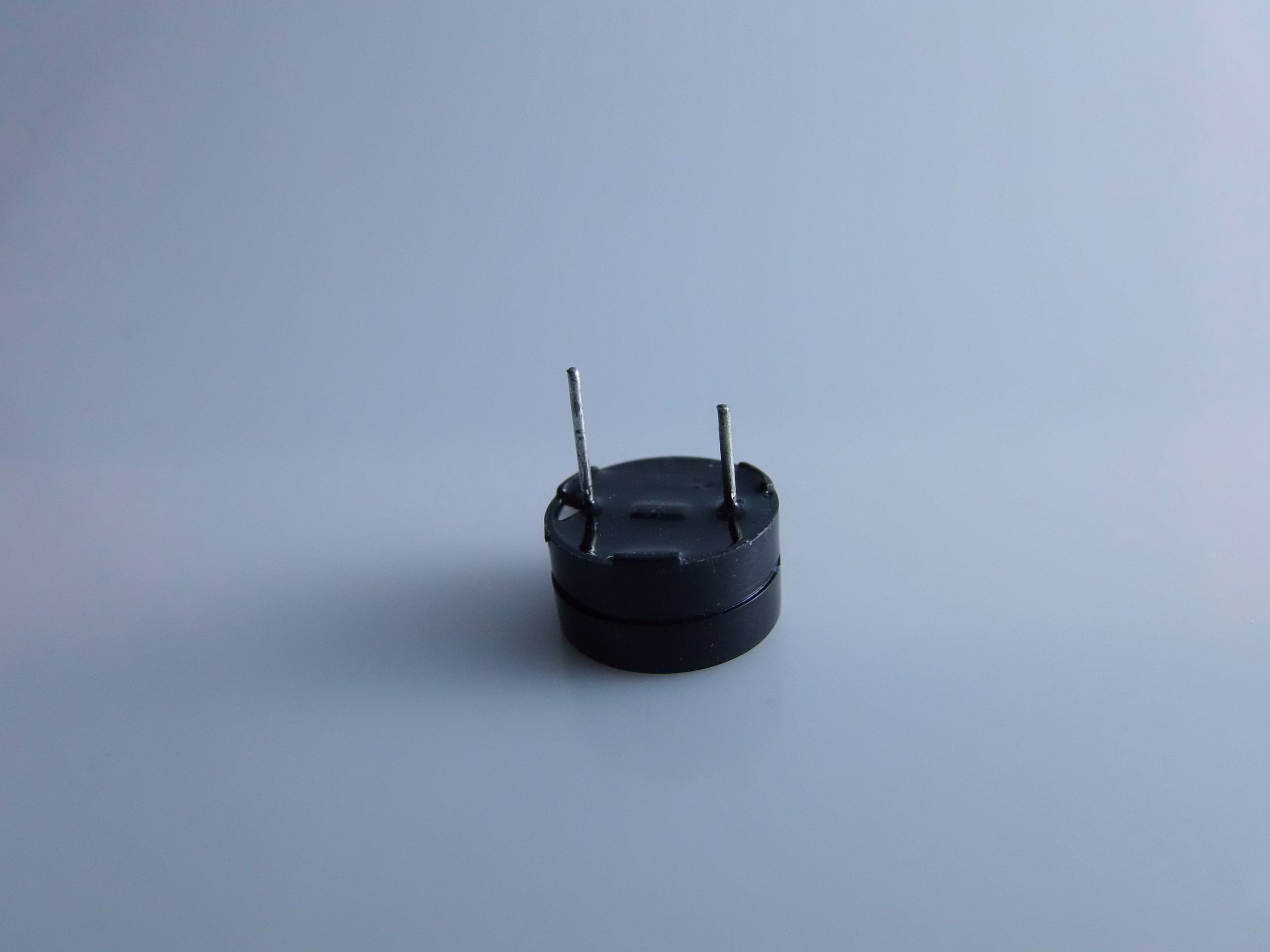
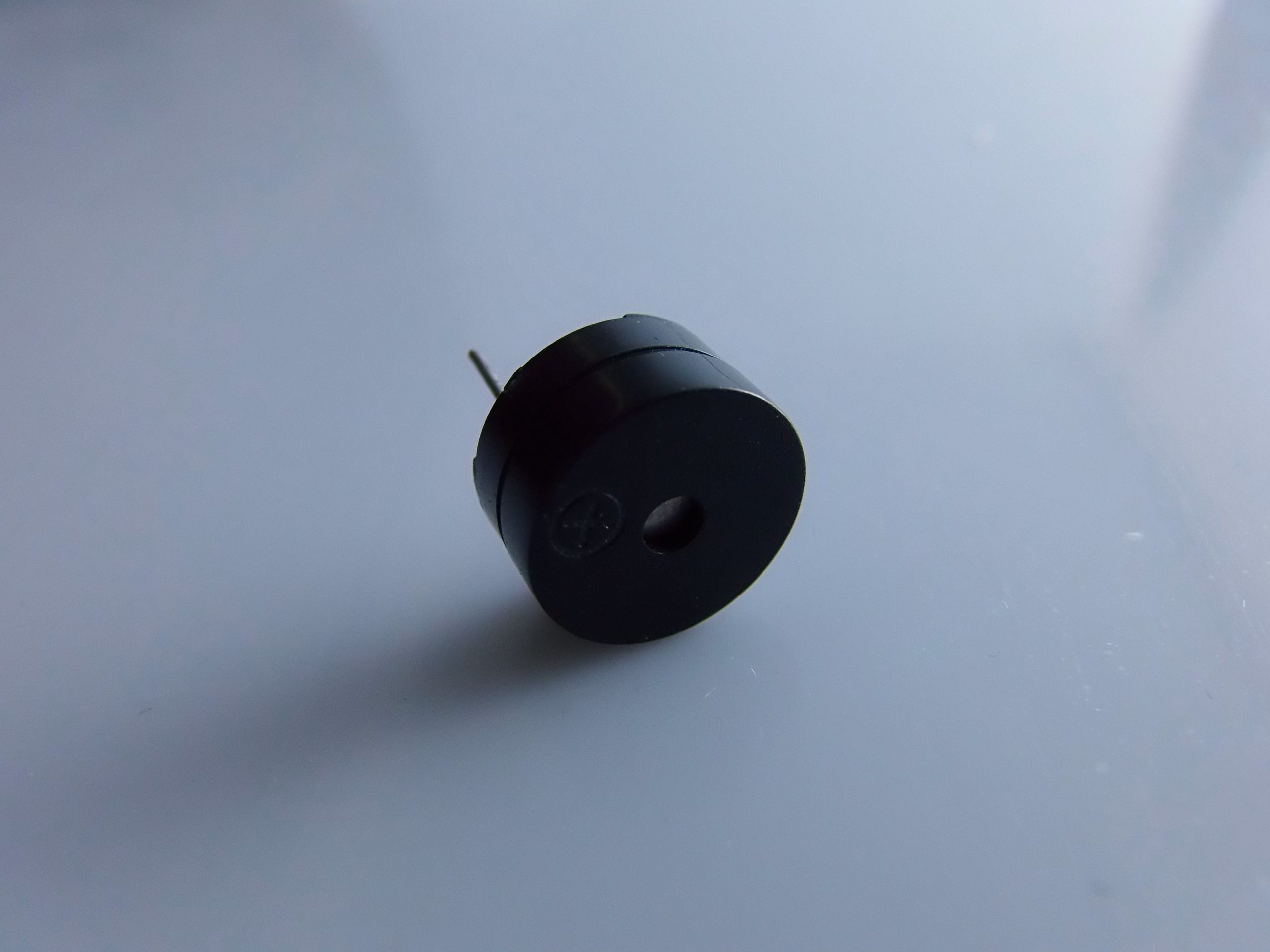
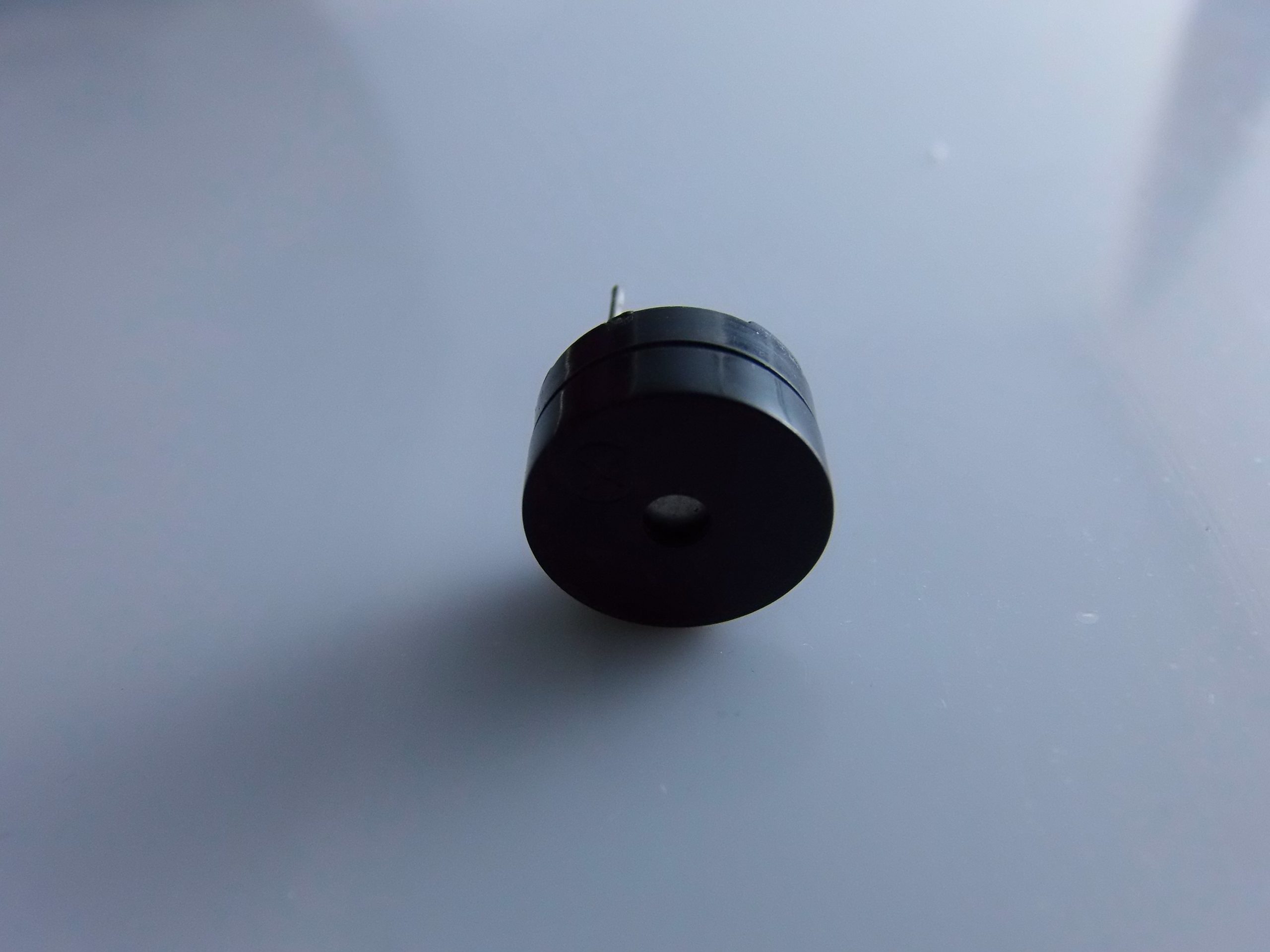
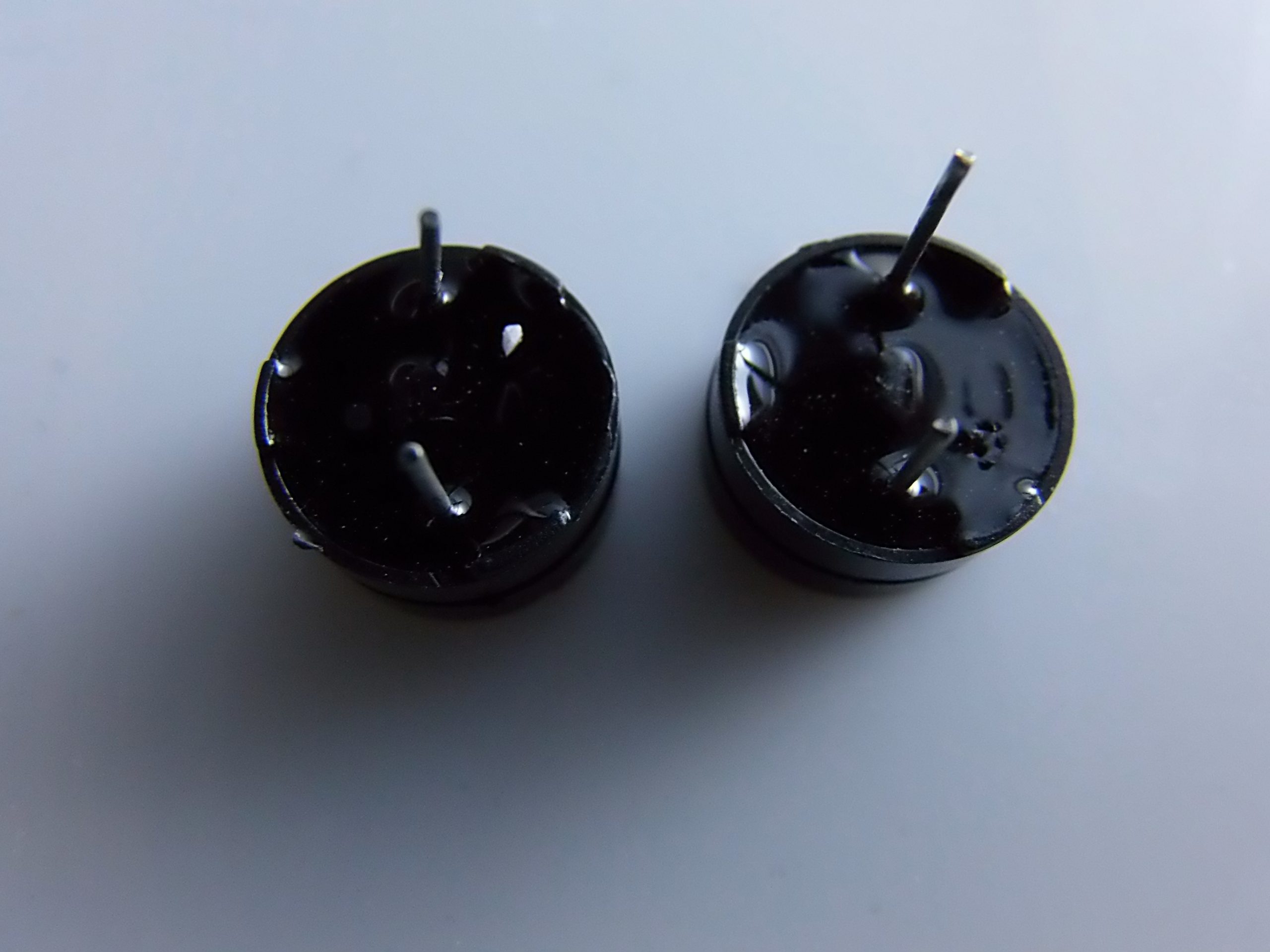

Description
Technical Specifications
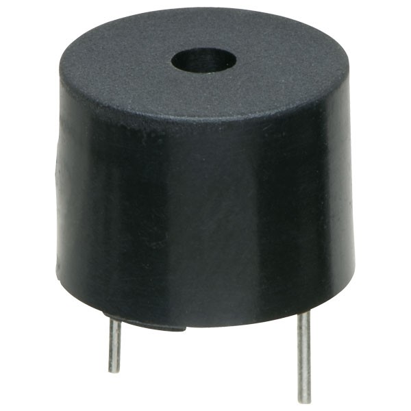
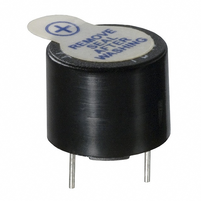
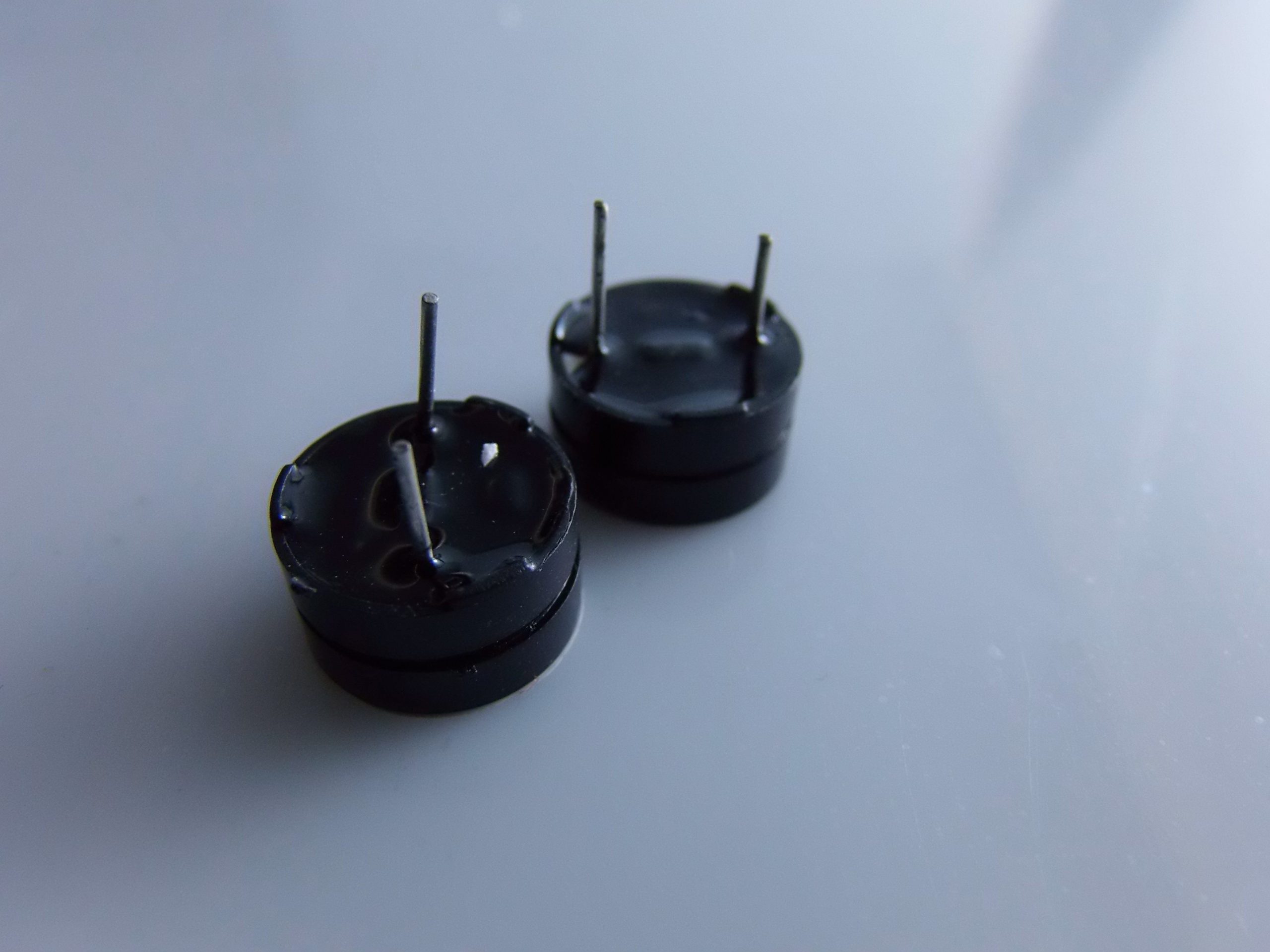
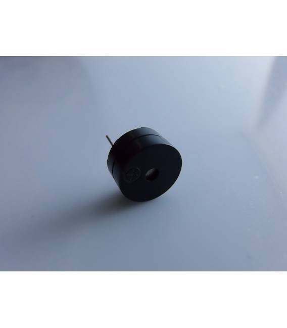
The BUZZER 5V module is an electronic component used to generate sounds, tones, or acoustic alarms in projects based on Arduino or other microcontrollers. It can be active or passive, with an integrated oscillator in the active case, making the use of the component simpler. In the passive case, a frequency signal must be provided to generate a sound, using functions like tone() in Arduino. This module is suitable for audible indications such as alerts, input confirmations, timers, and error notifications.
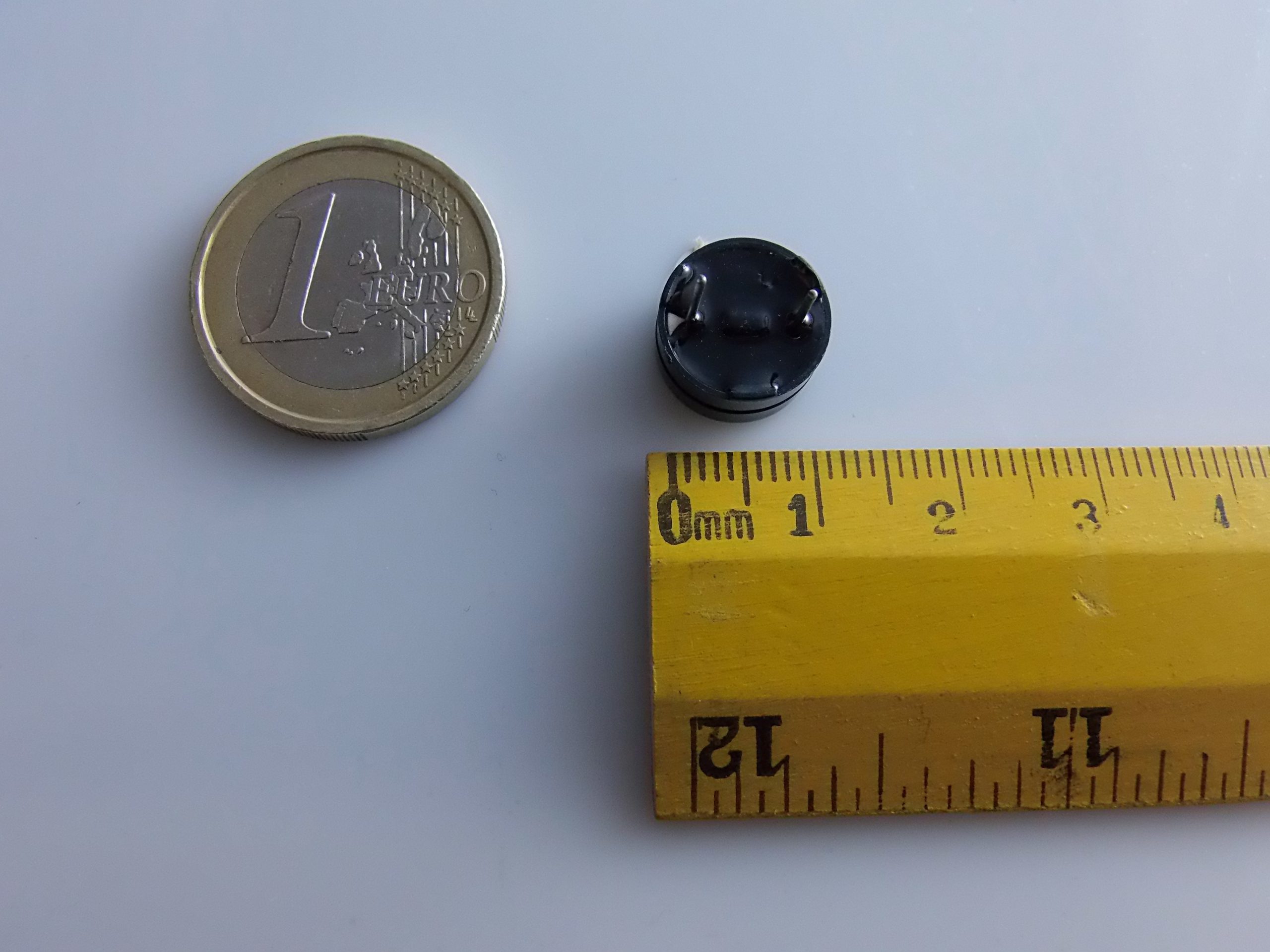
The BUZZER 5V module features two power pins (VCC and GND) and, in some cases, a third signal pin. The module size is compact, typically less than 2 cm. The power supply voltage is 5V DC and the typical current ranges from 10 to 30 mA. The operating frequency is approximately 2kHz for active buzzers.
To use the 5V buzzer module, it is necessary to connect it correctly to the microcontroller. The signal pin configuration depends on the type of buzzer (active or passive) and the project requirements.
Key Specifications
| Parameter | Value |
| Supply Voltage | 5V DC |
| Buzzer Type | Active or Passive |
| Typical Current | 10-30 mA |
| Operating Frequency | ~2kHz (for active buzzer) |
| Interface | 2 Pin (VCC and GND) + (sometimes) signal pin |
| Dimensions | < 2cm |
| Quantity | 3 pieces |
| Container | N/D (see manufacturer’s technical sheet) |
Installation and Usage
- Connect the VCC pin of the buzzer module to the 5V pin of the microcontroller.
- Connect the GND pin of the buzzer module to the GND pin of the microcontroller.
- If present, connect the signal pin of the buzzer module to a digital pin of the microcontroller.
- Check that the buzzer module is properly powered and that the sound is emitted as expected.
- Perform a simple programming test to verify the functionality of the buzzer module.
Compatibility and Requirements
- The 5V buzzer module is compatible with Arduino, ESP8266, ESP32, Raspberry Pi, and other microcontrollers.
- To use the 5V buzzer module, a microcontroller with 5V power supply and an available digital pin is required.
- The 5V buzzer module can be used in prototyping, testing, and signaling applications.
Limitations and Important Notes
- The 5V buzzer module is not designed for long-term continuous use without interruptions.
- The 5V buzzer module is not designed to generate high-frequency or high-intensity sounds.
- The 5V buzzer module requires a microcontroller to be activated and controlled.
- The 5V buzzer module is not designed to be used with voltages higher than 5V.
Troubleshooting
The buzzer module does not emit sounds.
Probable cause: Incorrect or missing connection.
Solution: Check and reconnect the VCC and GND connectors. If present, check the signal pin connection.
The buzzer module emits intermittent sounds.
Probable cause: Insufficient or unstable power supply.
Solution: Check the microcontroller’s power supply and ensure it is stable and sufficient.
The buzzer module emits low-intensity sounds.
Probable cause: Insufficient power supply current.
Solution: Check the power supply voltage and increase the current if necessary.
The buzzer module does not respond to the microcontroller commands.
Probable cause: Coding error or signal pin connection error.
Solution: Check the microcontroller code and reconnect the signal pin if necessary.
Use cases
Arduino Prototyping Project
Objective: Generate an audio signal to indicate the start of a process.
What’s needed: 5V buzzer module.
Steps: 1) Connect the buzzer module to the microcontroller. 2) Program the microcontroller to generate a sound when the process starts. 3) Test the functionality of the buzzer module.
Expected result: The buzzer module emits a sound when the process starts.
Raspberry Pi System Test
Objective: Verify the integrity of the system.
What’s needed: 5V buzzer module.
Steps: 1) Connect the buzzer module to the Raspberry Pi. 2) Program the Raspberry Pi to generate a sound when the system is intact. 3) Test the buzzer module functionality.
Expected result: The buzzer module emits a sound when the system is intact.
Home security alarm system
Objective: Generate an acoustic alarm when abnormal conditions occur.
What is needed: 5V buzzer module.
Steps: 1) Connect the buzzer module to the security alarm system. 2) Program the security alarm system to activate the buzzer module when abnormal conditions occur. 3) Test the buzzer module functionality.
Expected result: The buzzer module emits an acoustic alarm when abnormal conditions occur.
Environmental monitoring system
Objective: Generate an acoustic signal when environmental changes occur.
What is needed: 5V buzzer module.
Steps: 1) Connect the buzzer module to the environmental monitoring system. 2) Program the environmental monitoring system to activate the buzzer module when environmental changes occur. 3) Test the functionality of the buzzer module.
Expected result: The buzzer module emits an audible signal when environmental changes occur.
Industrial automation project
Objective: Generate an audible signal to indicate the end of a production cycle.
Required: 5V buzzer module.
Steps: 1) Connect the buzzer module to the industrial automation system. 2) Program the industrial automation system to activate the buzzer module when the production cycle ends. 3) Test the functionality of the buzzer module.
Expected result: The buzzer module emits an audible signal when the production cycle ends.
Electronic testing project
Objective: Verify the functionality of the buzzer module.
What’s needed: 5V buzzer module.
Steps: 1) Connect the buzzer module to the microcontroller. 2) Program the microcontroller to generate a sound. 3) Test the functionality of the buzzer module.
Expected result: The buzzer module emits a sound when the microcontroller activates it.
Prototype project of a security system
Objective: Generate an audio signal when abnormal conditions occur.
What’s needed: 5V buzzer module.
Steps: 1) Connect the buzzer module to the security system. 2) Program the security system to activate the buzzer module when abnormal conditions occur. 3) Test the functionality of the buzzer module.
Expected result: The buzzer module emits an audio signal when abnormal conditions occur.
Prototype project of an air quality monitoring system
Objective: Generate an audible signal when abnormal conditions occur.
What’s needed: 5V buzzer module.
Steps: 1) Connect the buzzer module to the air quality monitoring system. 2) Program the air quality monitoring system to activate the buzzer module when abnormal conditions occur. 3) Test the functionality of the buzzer module.
Expected result: The buzzer module emits an audible signal when abnormal conditions occur.
In the package
- 3 pieces
Complete the project
- Diagnostic acoustic signal for the internal speaker buzzer / motherboard for PC: To test and prototype the 5V buzzer module.
Technical FAQs
Does the 5V buzzer module emit intermittent sounds?
Check the microcontroller power supply and ensure it is stable and sufficient.
The 5V buzzer module does not respond to microcontroller commands?
Check the microcontroller code and reconnect the signal pin if necessary.
What are the limitations of the 5V buzzer module?
The 5V buzzer module is not designed for continuous long-term use without breaks, it is not designed to generate high-frequency or high-intensity sounds, it requires a microcontroller to be activated and controlled, it is not designed to be used with voltages higher than 5V.
How to connect the 5V buzzer module to the microcontroller?
Connect the VCC pin of the buzzer module to the 5V pin of the microcontroller, connect the GND pin of the buzzer module to the GND pin of the microcontroller, if present, connect the signal pin of the buzzer module to a digital pin of the microcontroller.
Tutorial: How to use 5V Acoustic Buzzer for Arduino
This 5V acoustic buzzer is ideal for creating simple audio signals in Arduino projects. It’s perfect for both beginners and intermediate makers.
What you need
- Arduino
- 5V Acoustic Buzzer
- Jumper wire
Steps
- Connect the buzzer to your Arduino board following the instructions in the product datasheet.
- Check polarity: usually, the longer ring is the + (positive), while the shorter ring or no ring indicates – (negative).
- Write an Arduino sketch that sends a HIGH and LOW signal to the buzzer to produce sounds.
- Modify the frequency and duration of the signal to create different sound effects.
- Check functionality: listen if the buzzer emits sounds as expected.
- If necessary, add a resistor between the Arduino and the buzzer to protect the board.
Example code
void setup() {
 pinMode(9, OUTPUT);
}

void loop() {
 tone(9, 1000); // Emetti suono a 1kHz
 delay(500);
 noTone(9); // Fermare il suono
 delay(500);
}
Mini project
Create a simple alarm that emits an audio signal when a door or window is opened.
Common mistakes
- Do not check the polarity of the buzzer.
- Do not add a protective resistor.
- Set frequencies too high for the buzzer.
- Use excessive voltage (higher than 5V).
Recommended accessories
- Protective resistance
- Motion sensors
- Relay Module
- LED Indicators
Frequently asked questions
My buzzer is not making any sound, what happens?
Check polarity and make sure you have connected the circuit correctly.
Can I use this buzzer with voltages below 5V?
Check the datasheet to understand the power supply specifications of your buzzer.



Reviews
There are no reviews yet.