 EN
 IT Italiano
 ES Español
 FR Français
 DE Deutsch
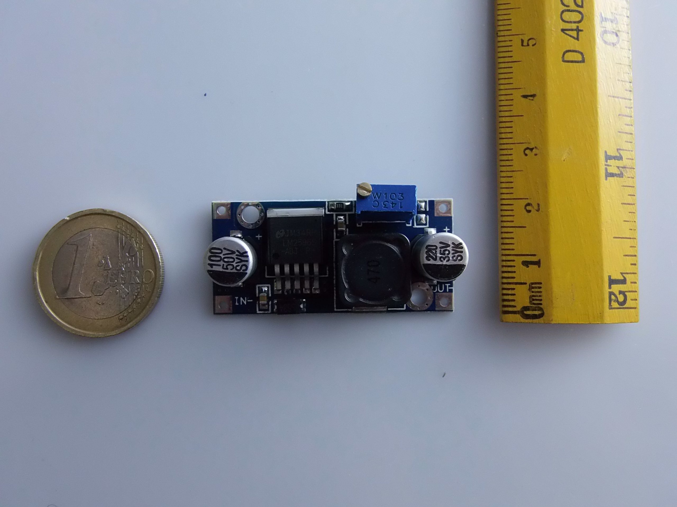
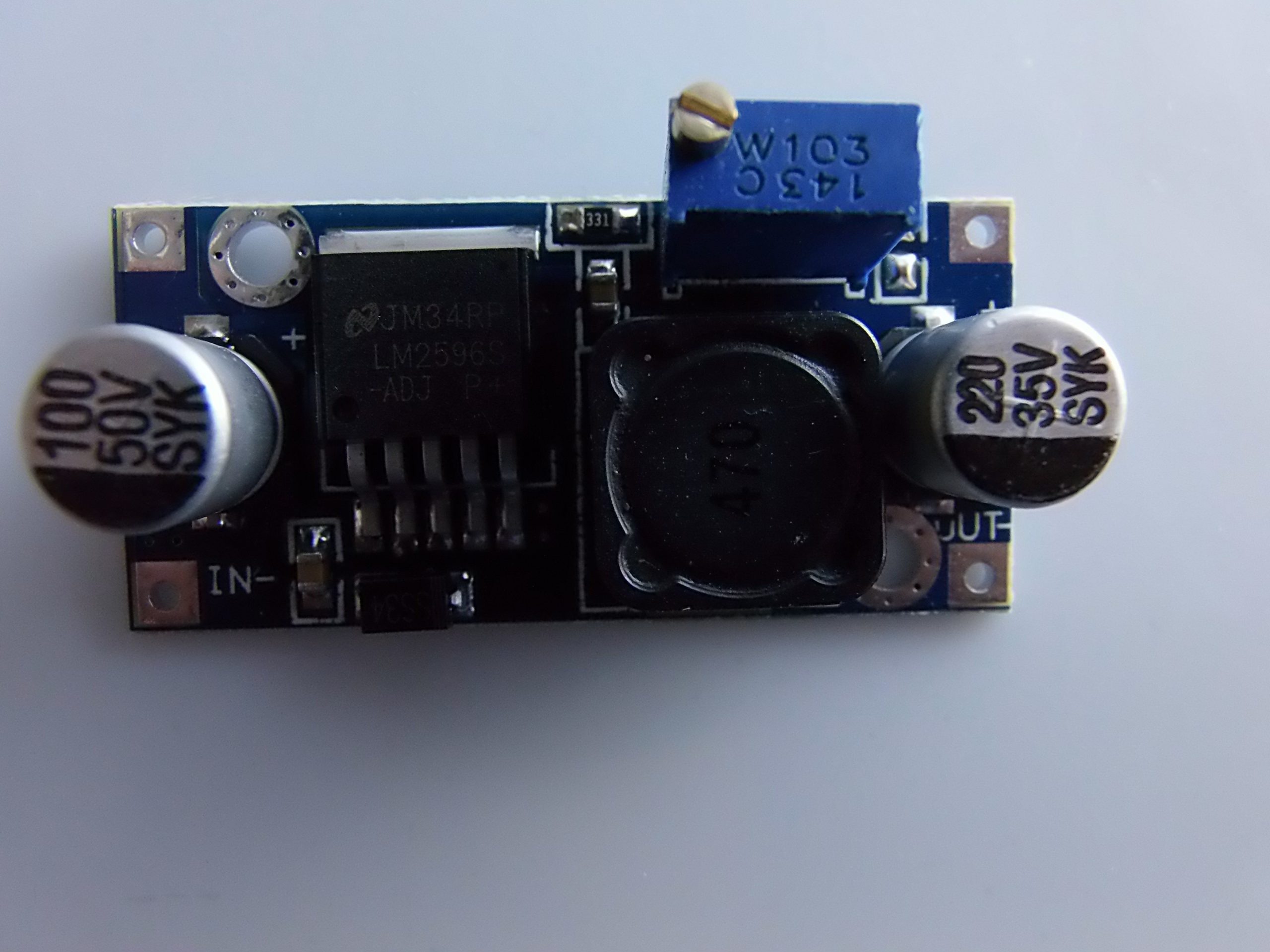
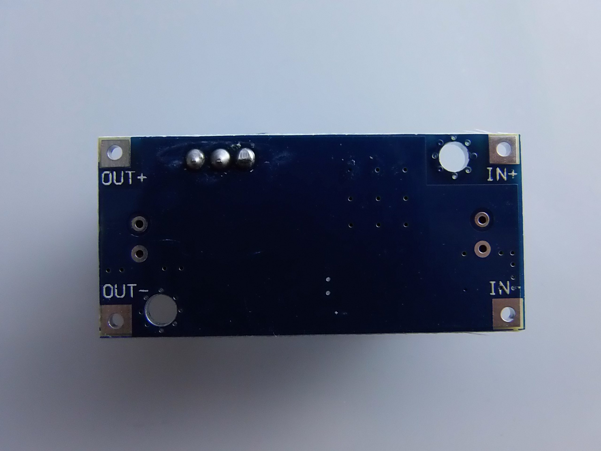
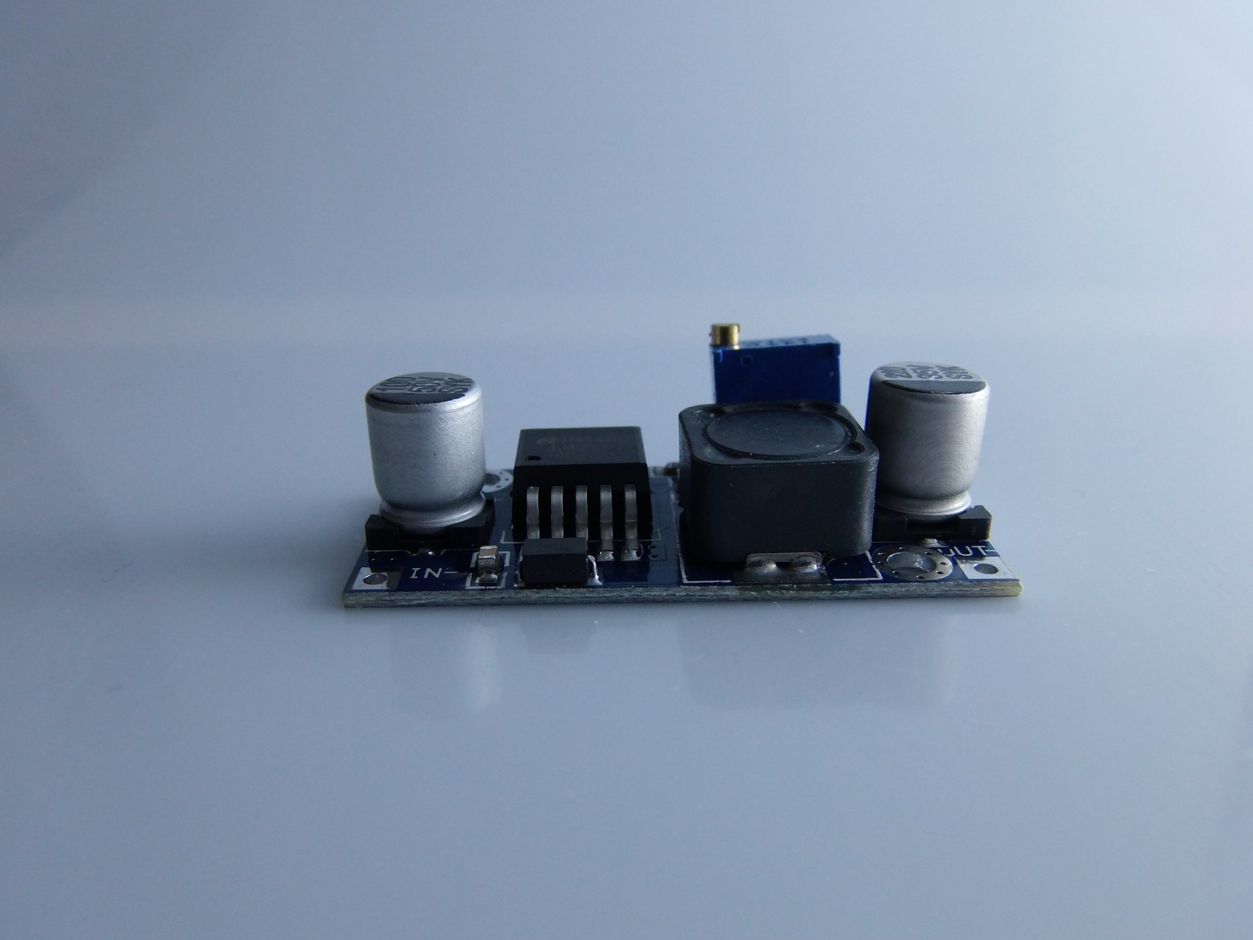
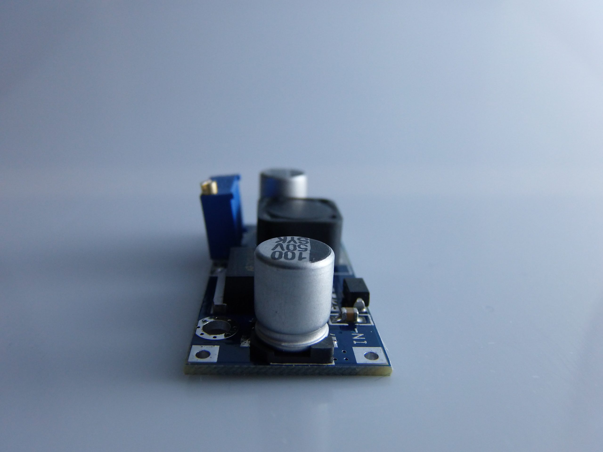
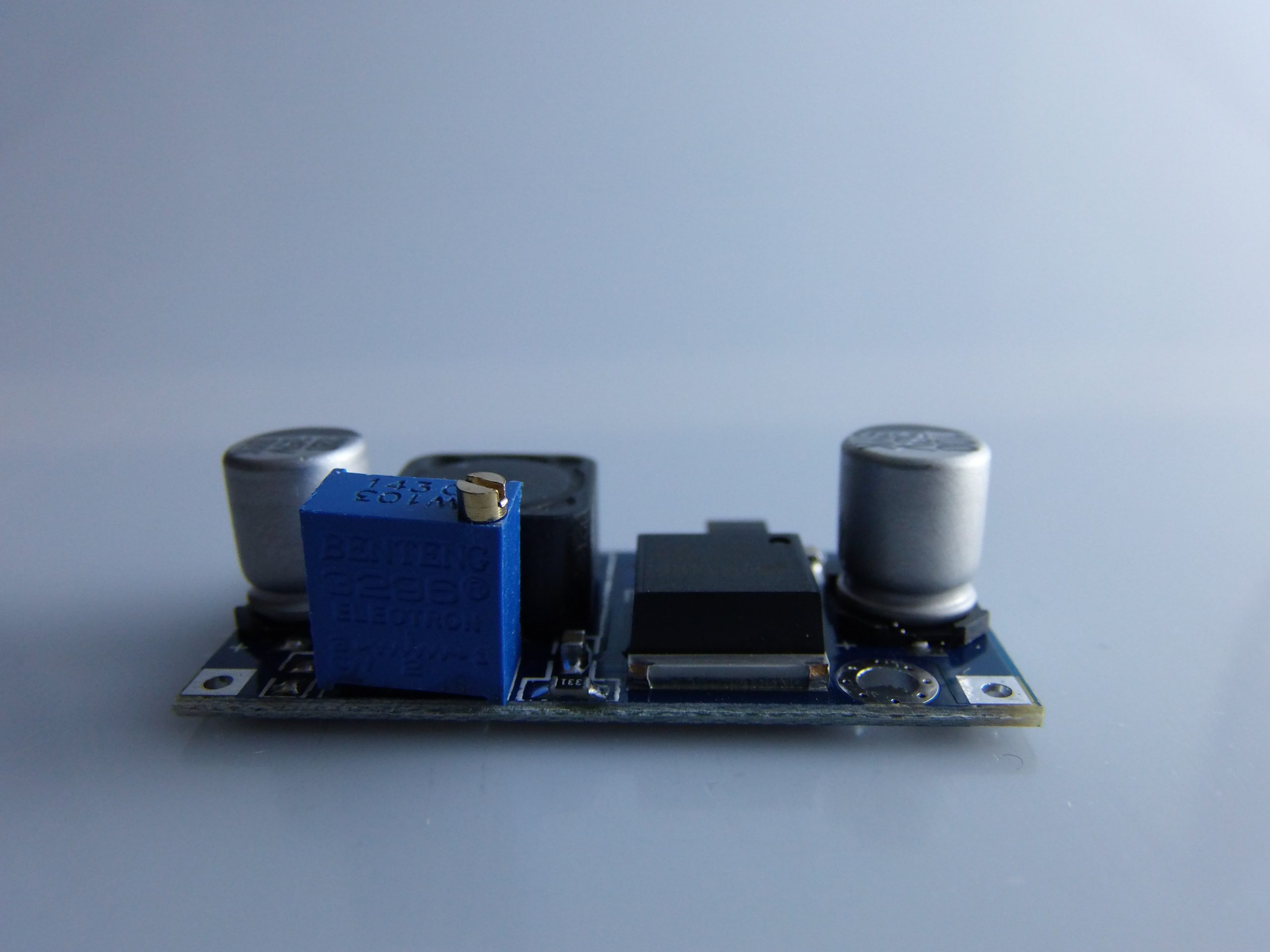
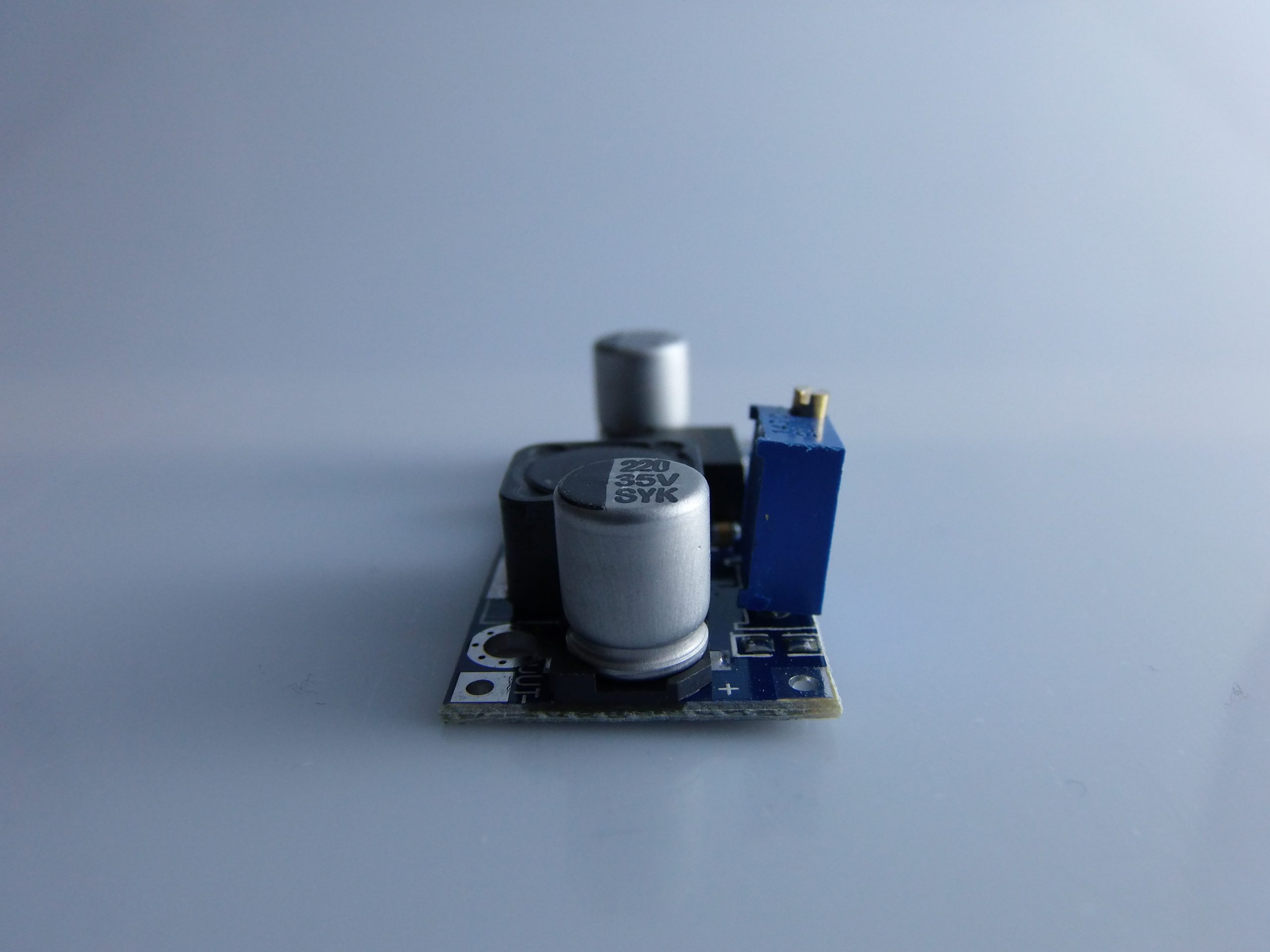
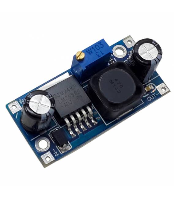
Description
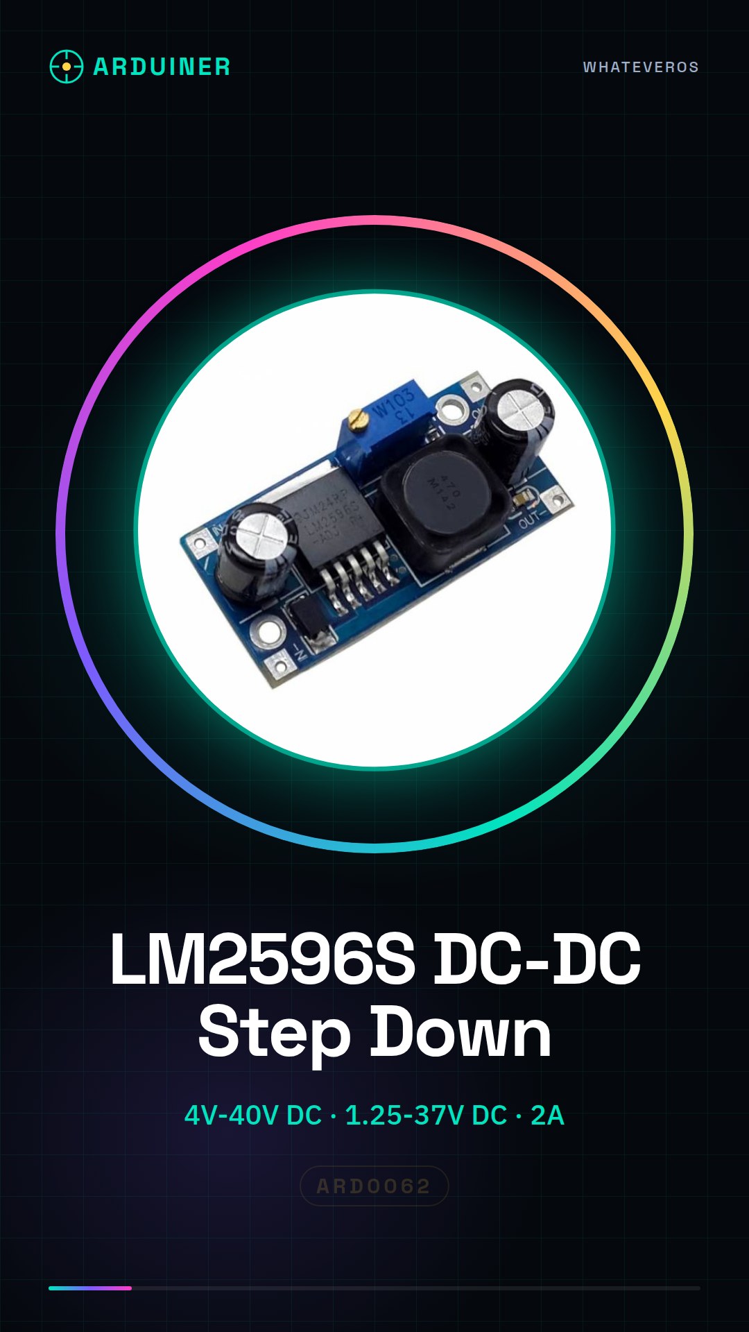
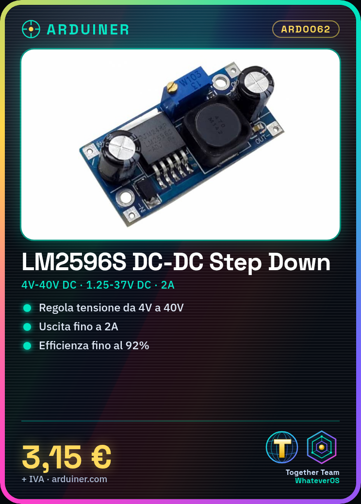
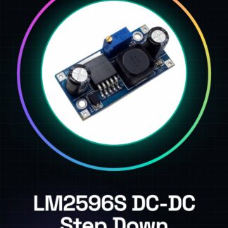
📦 Complete Module Description LM2596S Adjustable DC-DC Step Down Converter (5V 12V 2A Power Supply for Arduino)
✅ Technical Specifications
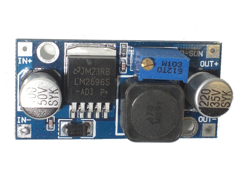
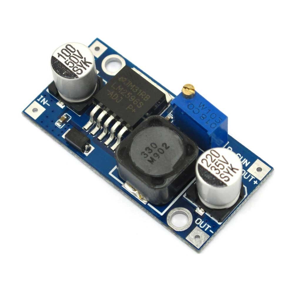
The LM2596S module is an adjustable step-down (buck) DC-DC converter adjustable, which allows the input voltage to be reduced to a lower adjustable voltage through a potentiometer. This makes it ideal for projects with Arduino, Raspberry Pi or other microcontrollers that require a stable lower voltage than what is available.
- Main chip: LM2596S
- Type of conversion: Step-down (buck)
- Input voltage: 4V – 40V DC
- Adjustable output voltage: 1.25V – 37V DC
- Maximum output current: 2A continuous (with dissipation), up to 3A with adequate cooling
- Efficiency: up to 92%
- Switching Frequency: 150 kHz
- Protection: against short circuit, overheat
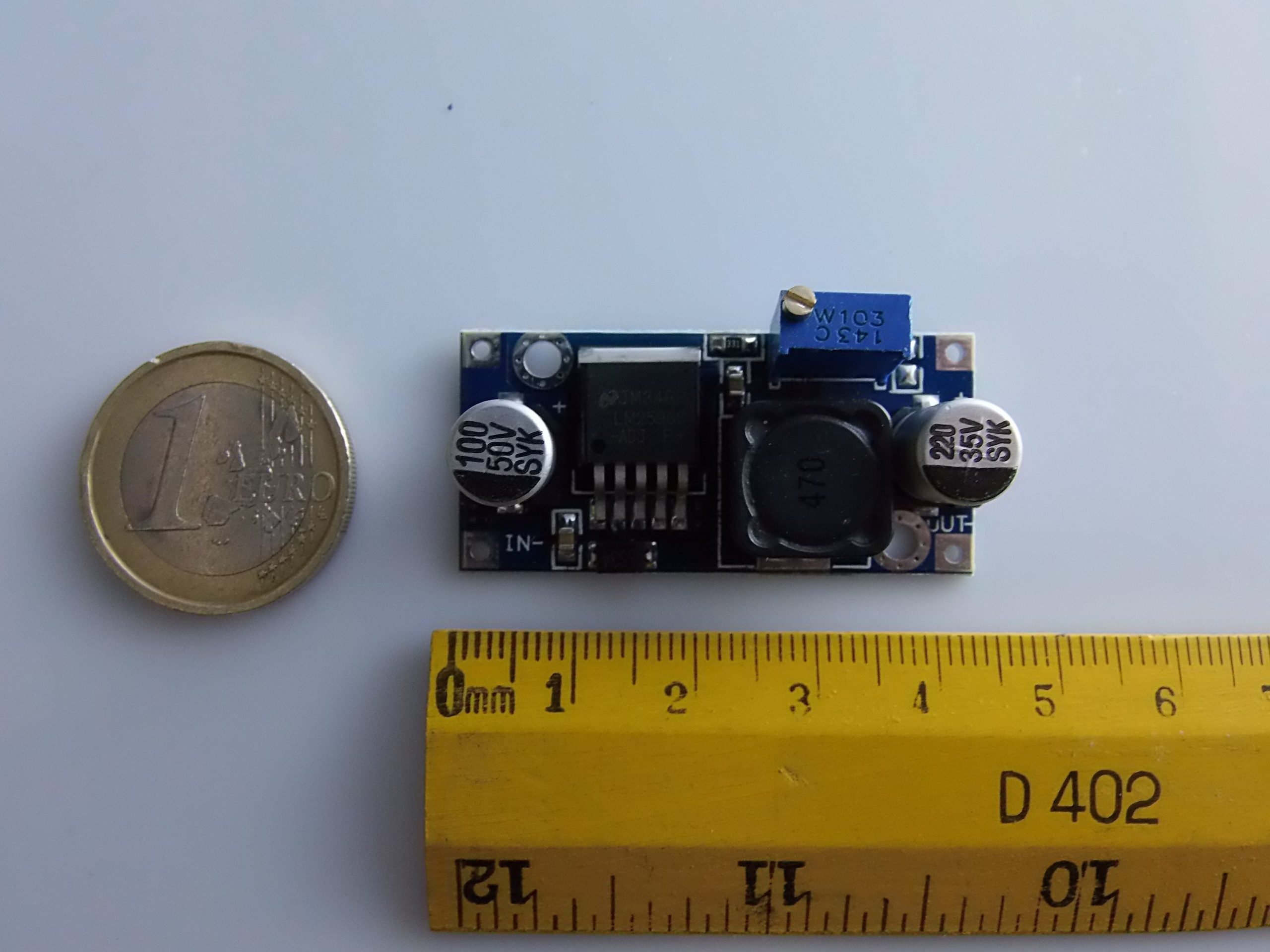
- Dimensions: approximately 43mm x 21mm x 14mm
🎯 Typical Applications
- Power Arduino from a 12V or 9V battery
- Battery-powered IoT projects
- Voltage regulation for LEDs, motors, sensors
- Adjustable power supplies for workbench
- Automotive projects (12V to 5V for USB modules, GPS, etc.)
🔧 How to Use the Module with Arduino
⚙️ Electrical Connections
| LM2596S Module Pins | Connection |
|---|---|
| IN+ | V+ (e.g., 9V, 12V, battery or DC power supply) |
| IN- | GND power |
| OUT+ | VCC for Arduino or other load |
| OUT- | GND common with Arduino |
⚠️ Important Note: adjust the output voltage before connecting the module to Arduino.
🧪 Steps for Initial Configuration
- Connect only power (IN+ and IN-) to the module.
- With a multimeter, measure the voltage between OUT+ and OUT-.
- Turn the trimmer (small blue screw) with a screwdriver to adjust the desired voltage (e.g., 5V for Arduino UNO).
- Once correctly set, connect OUT+ to VIN of Arduino and OUT- to GND.
💻 Usage Examples with Arduino
✅ Example 1: Power Arduino UNO from a 12V battery
Batteria 12V
   |
   |--> IN+ (LM2596)
   |
  GND --> IN- (LM2596)

OUT+ (5V regolati) --> VIN (Arduino UNO)
OUT- (GND)         --> GND (Arduino UNO)
✅ Example 2: Power 3.3V sensors with 5V Arduino
- Input: 5V (from Arduino or power supply)
- Regulated output: 3.3V → for sensitive modules (e.g., ESP8266, sensors)
Connect IN+ to 5V, IN- to GND. Adjust OUT+ to 3.3V and connect the sensor.
📘 Arduino Programming (Basic Guide)
The module does not require code, as it only regulates voltage. However, here is an example of how to verify the voltage supplied to a module (e.g., sensor) with Arduino and the converter:
🧪 Example 3: Reading regulated voltage
const int analogPin = A0; // Collegato a OUT+ del modulo LM2596
float voltage = 0;

void setup() {
  Serial.begin(9600);
}

void loop() {
  int sensorValue = analogRead(analogPin);
  voltage = sensorValue * (5.0 / 1023.0); // se Arduino è a 5V
  Serial.print("Tensione misurata: ");
  Serial.print(voltage);
  Serial.println(" V");
  delay(1000);
}
🔎 Tips
- Use a voltage divider if measuring voltages above 5V with Arduino.
- If the module overheats, add a heatsink or fan.
- Always regulate the voltage before connecting sensitive devices.
🧰 Recommended Tools
- Digital multimeter (for calibration)
- Mini star screwdriver for the trimmer
- Breadboard or clips for prototyping
- Aluminum heatsink (optional for high currents)
📌 Conclusion
The LM2596S DC-DC module is a reliable and cost-effective solution for powering low-voltage circuits from high-voltage sources. With its flexibility and ease of use, it is perfect for projects with Arduino, ESP32, Raspberry Pi and more.
Below I describe the Fritzing diagram for connecting the LM2596S module to an Arduino UNO, using a 12V battery as the source, and setting the output to 5V regulated to power the Arduino:
🧩 Fritzing Diagram – LM2596S Module Connection to Arduino UNO
📷 Required components:
- Arduino UNO
- LM2596S Module
- 12V Battery (or 9–24V power supply)
- Male-Male Jumper
- Multimeter (for calibration)
- (Optional) Breadboard
⚙️ Connections
| LM2596S Module | Arduino UNO | External Power Supply |
|---|---|---|
IN+ |
— | +12V of the battery |
IN- |
— | GND of the battery |
OUT+ |
VIN (o 5V*) |
— |
OUT- |
GND |
— |
⚠️ Connect to
VINif you are providing 5V or more to the Arduino. If you set exactly 5V on the output, you can also connect directly to the pin5V, but only if USB is not connected at the same time.
Tutorial: How to Use Adjustable DC-DC LM2596S Converter
The LM2596S voltage converter is an essential component for Arduino projects requiring adjustable power supply. Ideal for beginner and intermediate makers, it allows providing a stable current up to 2A.
What you need
- DC-DC Converter LM2596S
- Arduino Uno or Compatible
- USB Connection to Program Arduino
- Sensors (optional)
- Jumper Wires
Steps
- Connect the input voltage to the LM2596S converter. Check the datasheet for the acceptable voltage range.
- Adjust the potentiometer to obtain the desired output voltage (5V or 12V).
- Connect the common ground between the converter and Arduino.
- Connect the VOUT pins of the converter to the VIN pin of the Arduino.
- Check for short circuits with a multimeter.
- Upload a simple sketch to Arduino to test the power supply.
- If everything works, you can add sensors or other components to complete the project.
Mini project
Create a weather station with Arduino that measures temperature and humidity, powered by the LM2596S converter.
Common mistakes
- Incorrectly adjusting the output voltage.
- Connecting the input to a voltage higher than the acceptable range.
- Omit the ground connection between Arduino and converter.
- Use cables that are too thin to carry the current.
Recommended accessories
- Temperature and humidity sensors DHT11
- 16×2 LCD display
- Portable battery with USB jack
- Optocoupled relay
Frequently asked questions
How to adjust the voltage?
Use the potentiometer on the converter to obtain the desired output.
Can it power multiple devices?
Yes, but make sure the total current requirement does not exceed 2A of the converter.
Reviews
There are no reviews yet.