 EN
 IT Italiano
 ES Español
 FR Français
 DE Deutsch
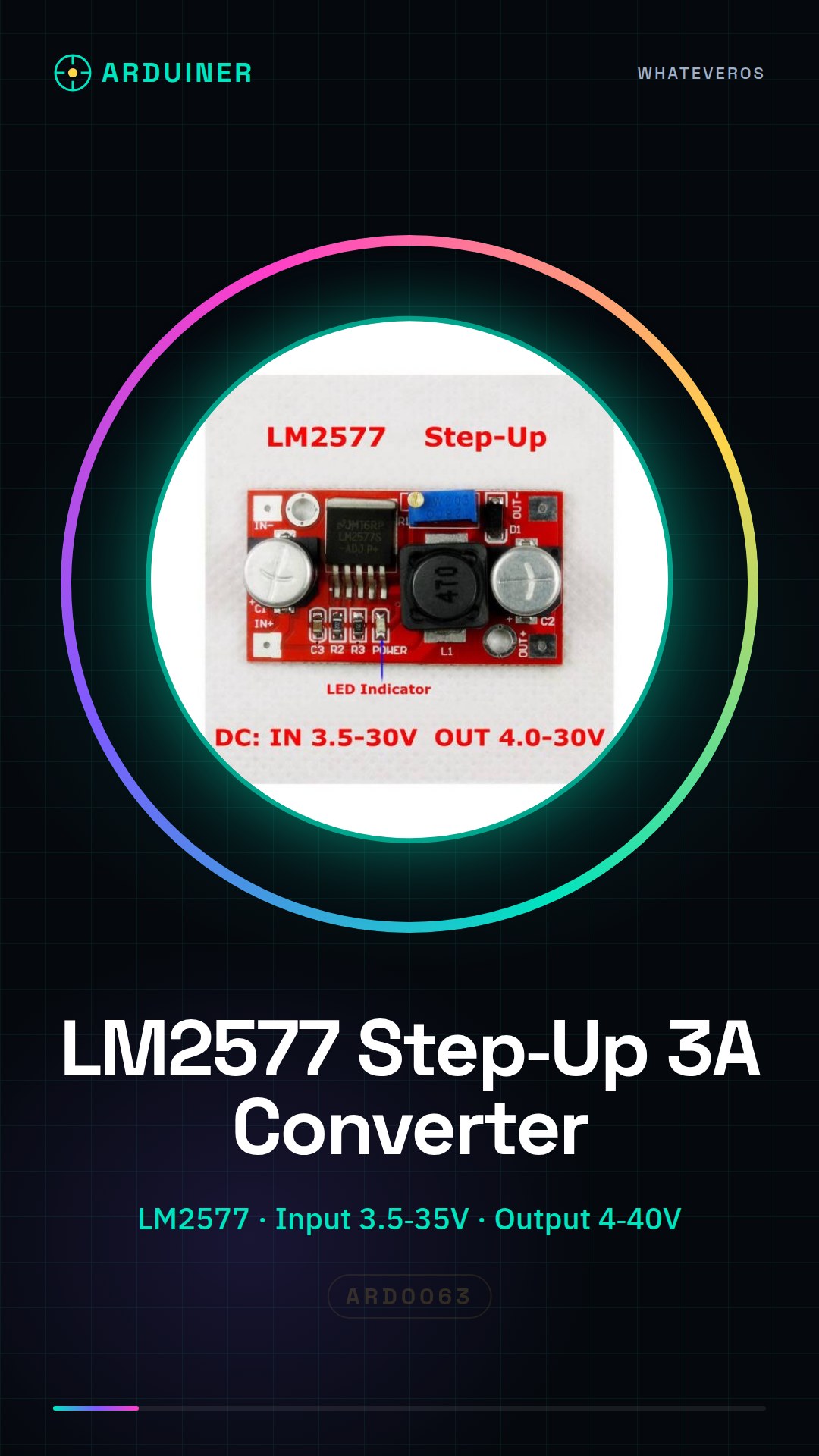
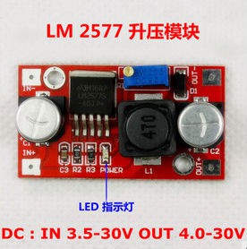
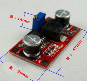
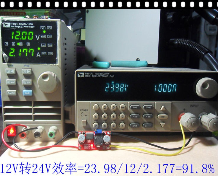
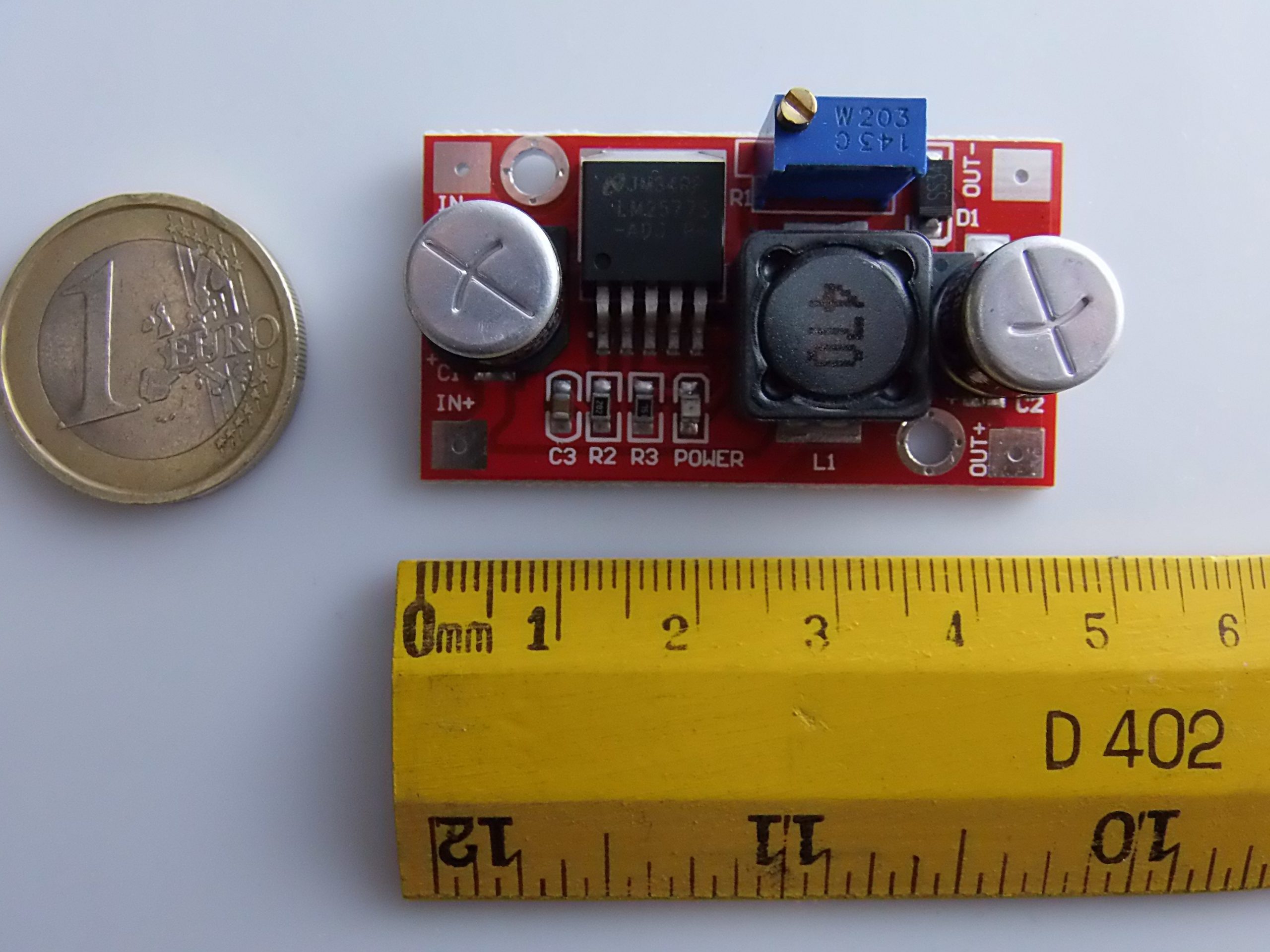
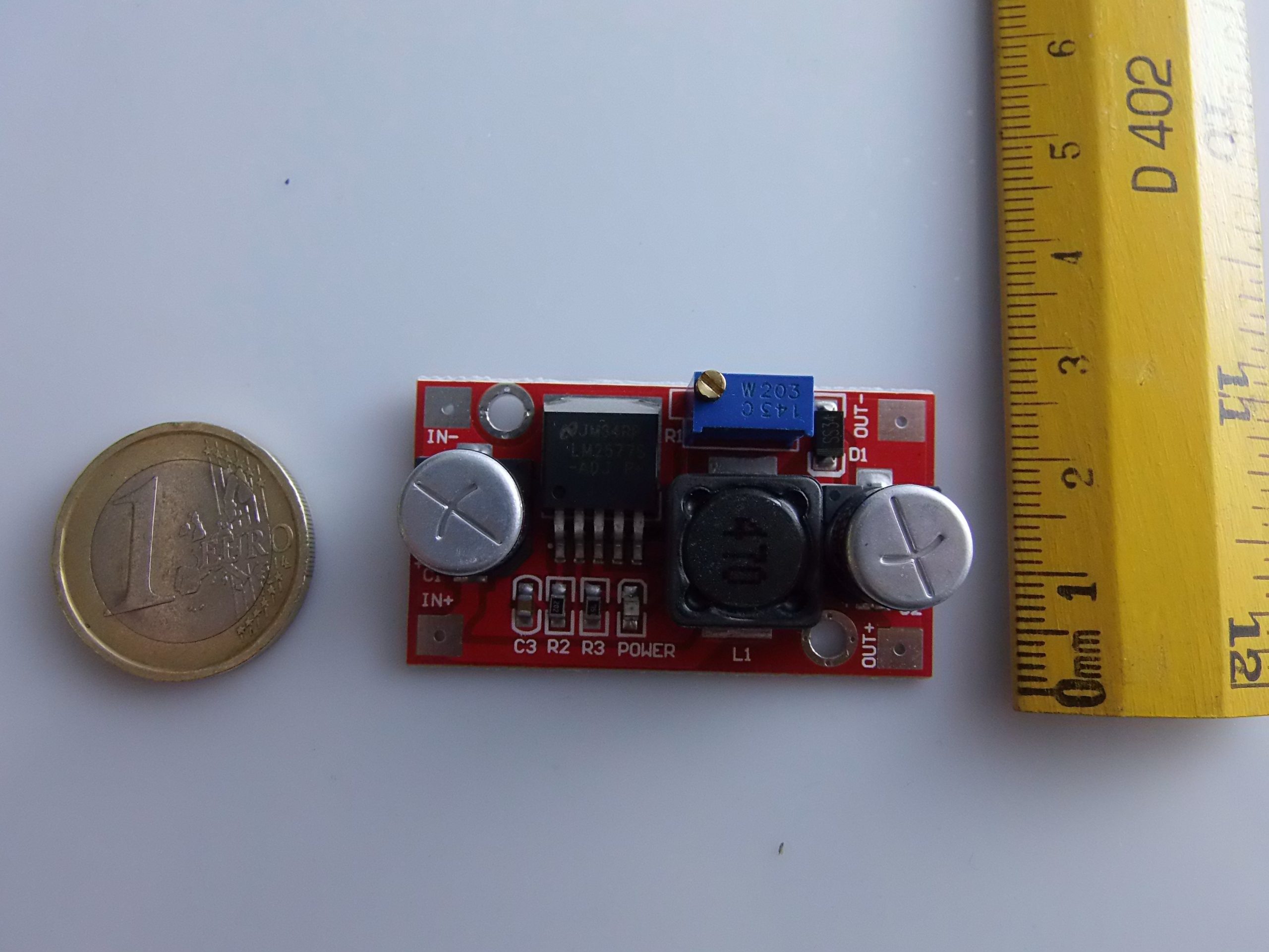
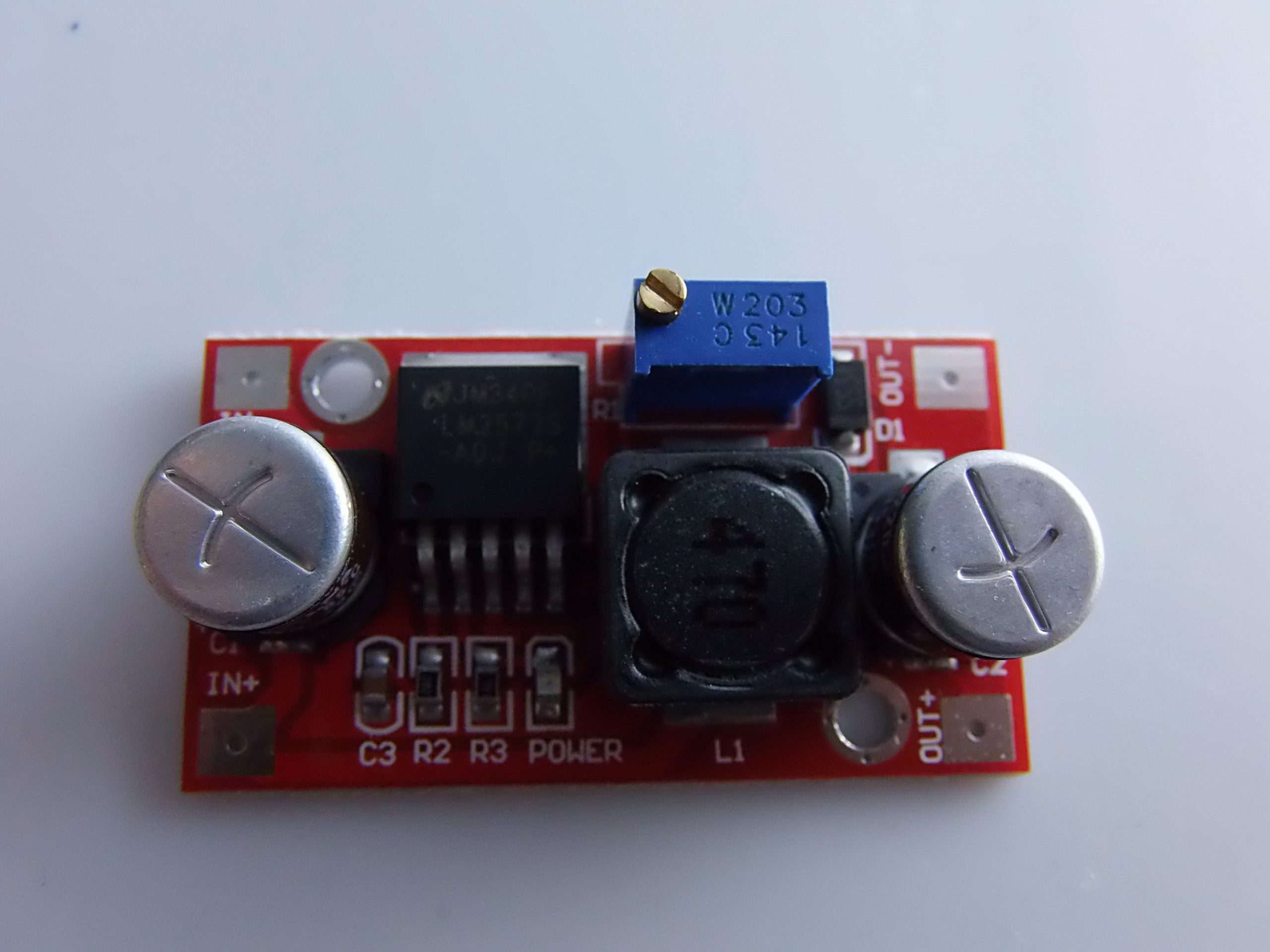
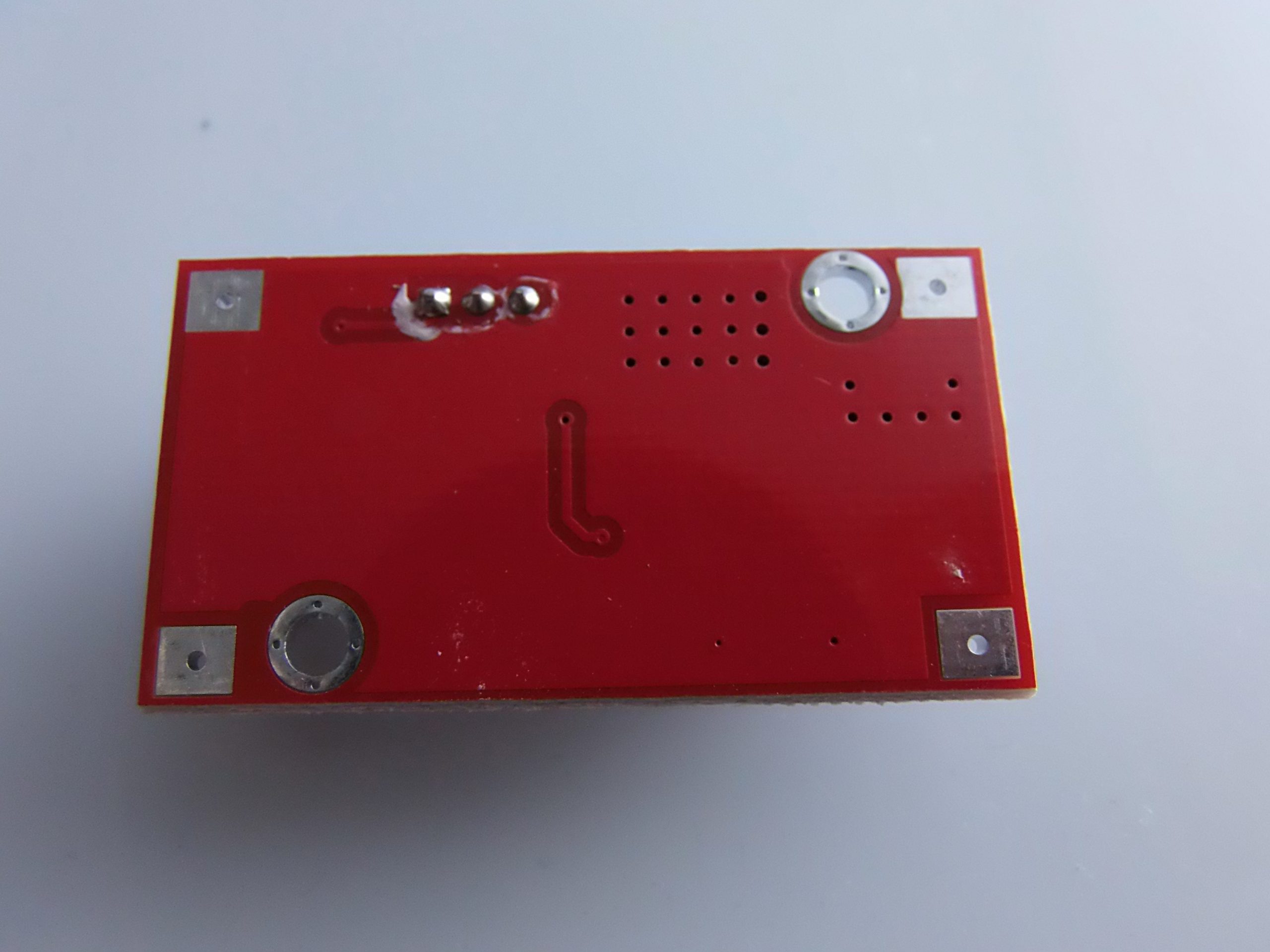
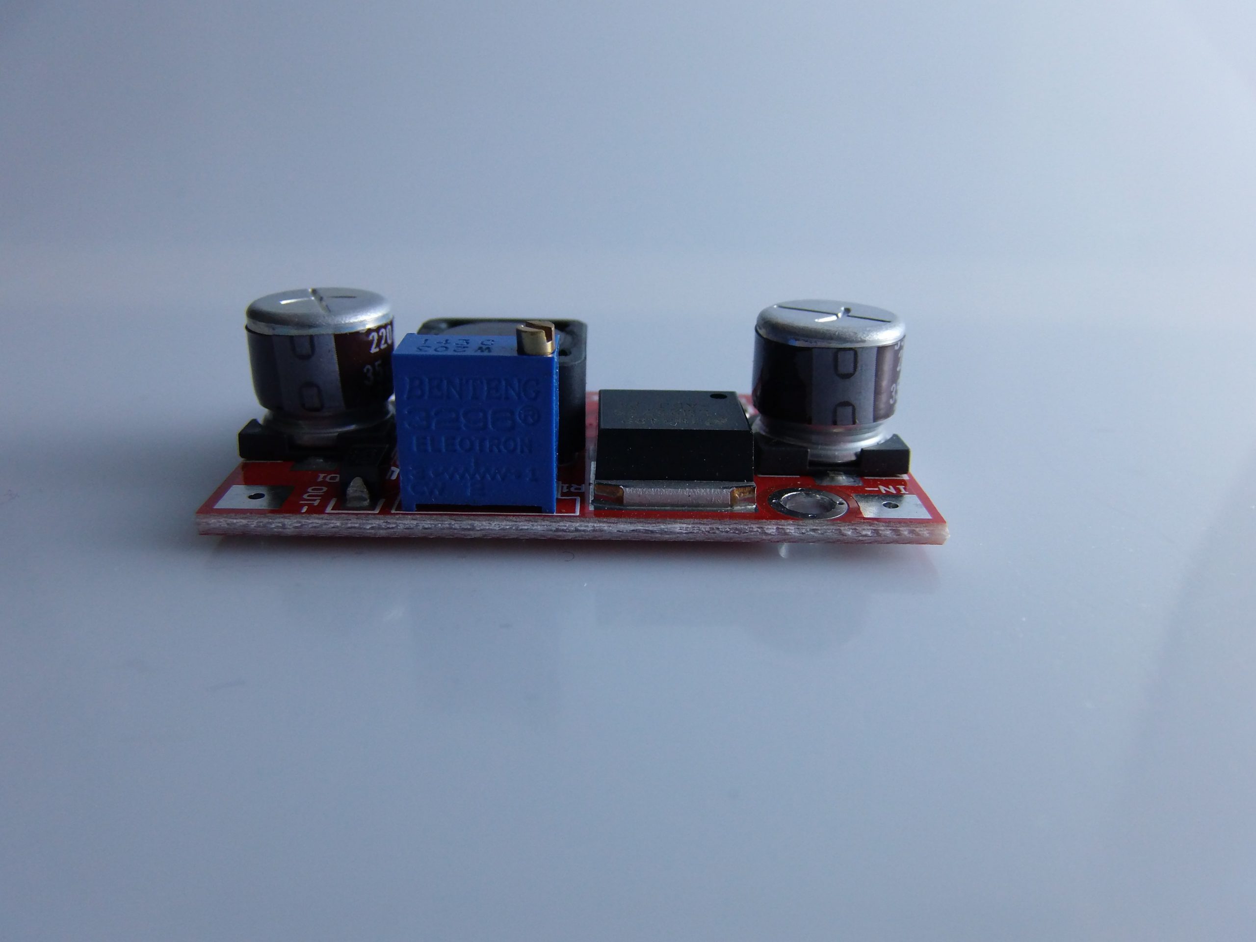
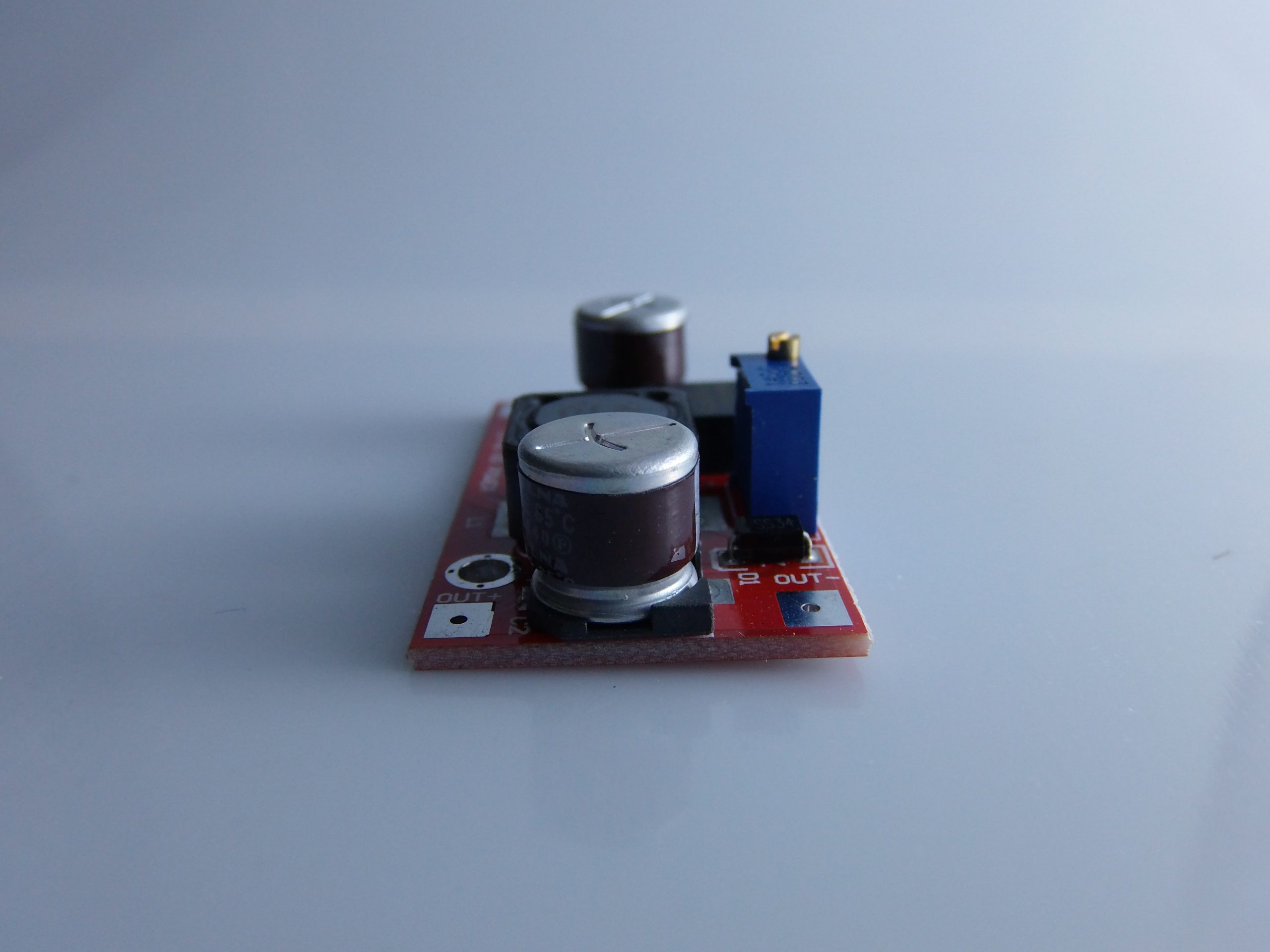
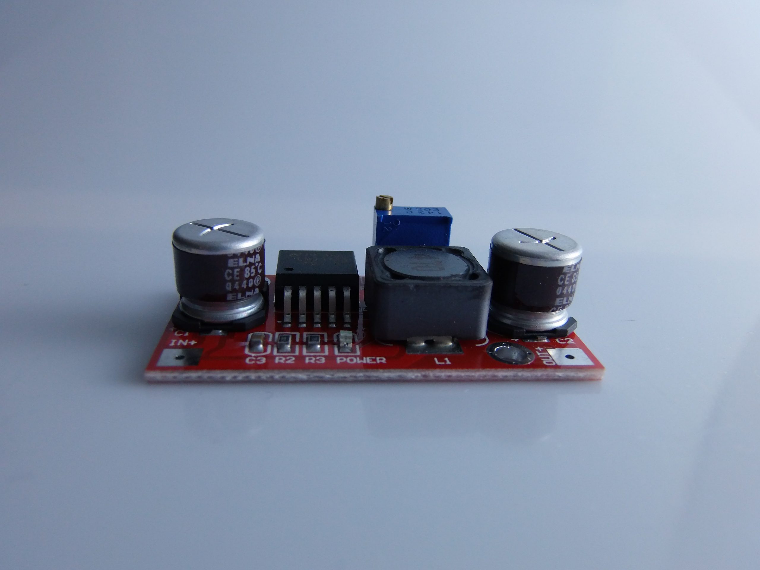
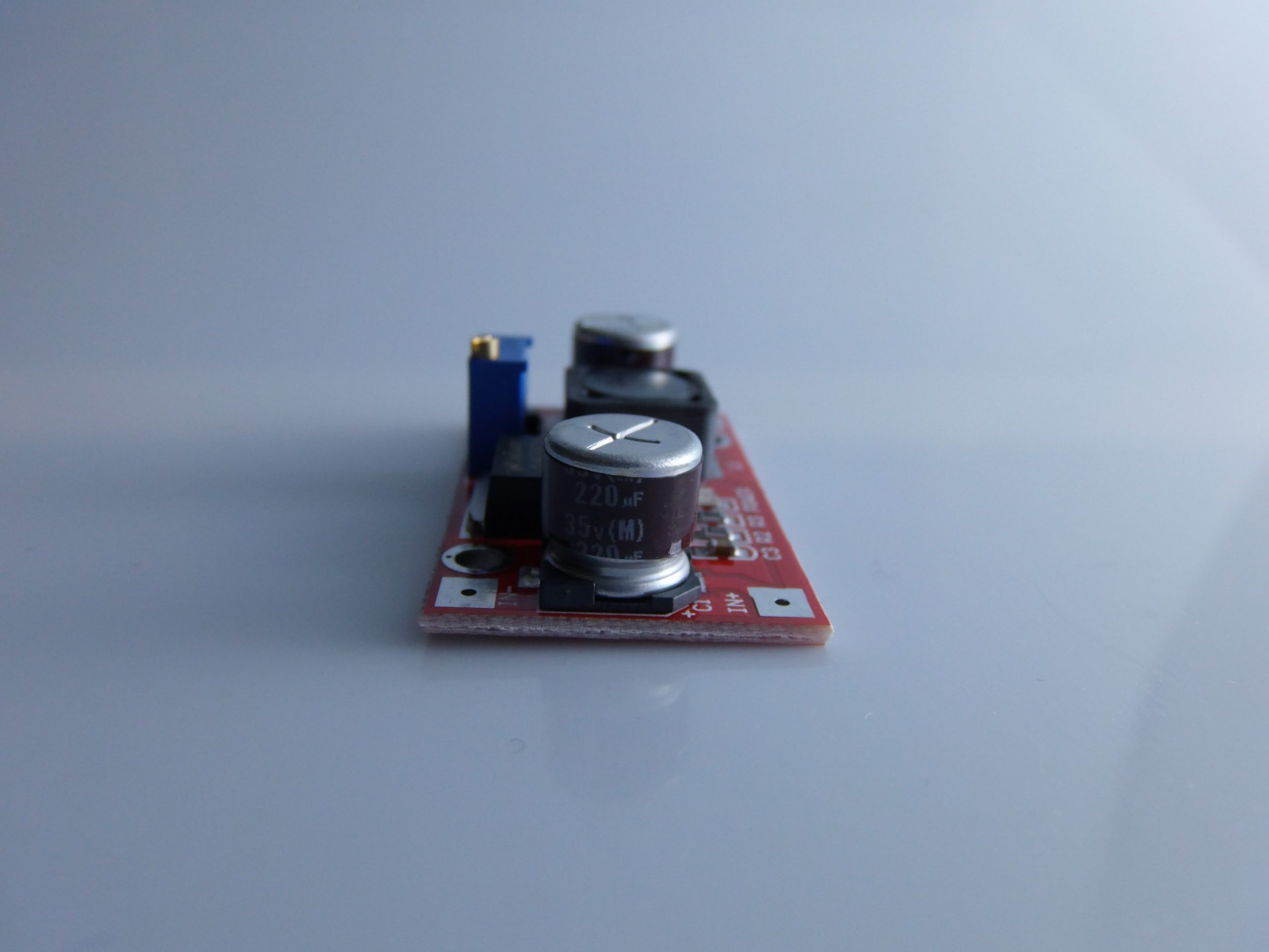
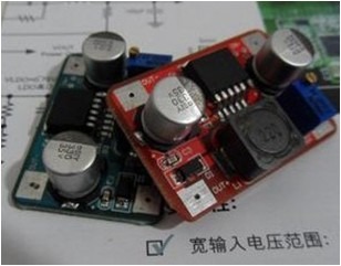
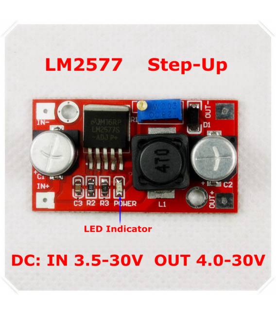
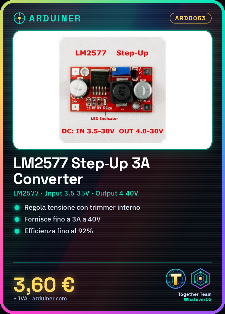
Description
📦 LM2577 Step-Up (Boost Converter) Variable DC-DC Power Supply Module for Arduino – Complete Description and Guide
🔧 1. LM2577 Step-Up (Boost Converter) Module Description
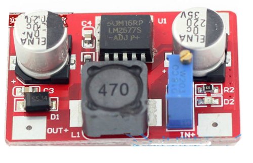
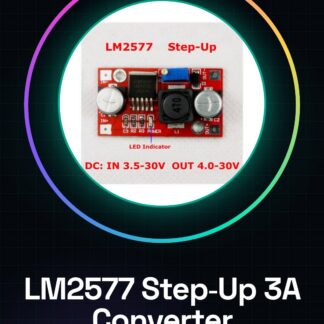
The LM2577 module is a DC-DC step-up (boost converter) that allows to increase a continuous input voltage (e.g., 3.5V-35V) to a higher output voltage up to 40V adjustable via an integrated potentiometer.
⚙️ Main Technical Specifications
- Control Chip: LM2577
- Type: Step-Up (Boost)
- Input Voltage: 3.5V – 35V DC
- Output Voltage: 4V – 40V DC (adjustable via trimmer)
- Maximum output current: up to 3A (depends on load and input voltage)
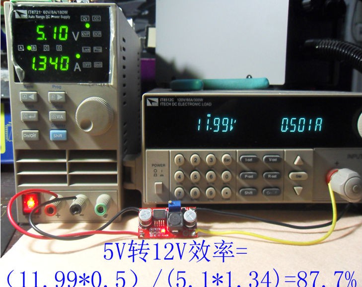
- Conversion efficiency: up to 92%
- Short circuit protection: No (must be added externally)
- Switching frequency: 52 kHz
- Dimensions: approximately 6.5 cm x 3.5 cm
🔌 2. Connections with Arduino
The LM2577 module IS NOT an intelligent module (does not have I2C/SPI communication), but a voltage regulator. It is used to supply Arduino or other components with a constant and regulated voltage.
🔗 Example Connection to Power Arduino:
If you want to power Arduino with a 7.4V battery (LiPo) and need 12V to power other modules, here is an example connection:
[ Batteria 7.4V ] → [ IN+ del LM2577 ]
 [ IN- del LM2577 ]
 ↓
 [ OUT+ → 12V ] —> Vin di Arduino (o modulo motori)
 [ OUT- → GND ] —> GND comune
⚠️ Important note: make sure that the output voltage is correct BEFORE connecting it to the ArduinoUse a multimeter to measure it and adjust with the trimmer.
💡 3. Examples of Use with Arduino
📘 Example 1 – Powering Arduino or sensors
Use the LM2577 module to provide a stable voltage to sensitive modules (e.g., a GSM module that requires 12V stability).
Schematic:
- IN: 7.4V battery
- OUT: 12V to GSM module
- Arduino powered separately or via VIN from the module
📘 Example 2 – Powering high-power LEDs
Use Arduino to control via PWM a MOSFET that drives LEDs powered by 24V generated with LM2577.
🧠 4. How to Use It in an Arduino Project
The module does not require direct programming, but you can use it in the context of a project to provide different voltages depending on the load. You can also read the output voltage through a voltage divider connected to an analog pin of Arduino.
📘 Example 3 – Monitoring the output voltage
// Pin analogico connesso a un partitore resistivo tra OUT+ e GND
const int tensionePin = A0;
float tensioneUscita = 0.0;

void setup() {
 Serial.begin(9600);
}

void loop() {
 int valoreADC = analogRead(tensionePin);
 // Calcolo della tensione: supponiamo un partitore 1:4 (es. 10kΩ e 30kΩ)
 float tensioneLetta = (valoreADC * 5.0) / 1023.0; // tensione sul pin
 tensioneUscita = tensioneLetta * 4.0; // riscalata dal partitore
 Serial.print("Tensione di uscita: ");
 Serial.print(tensioneUscita);
 Serial.println(" V");

 delay(1000);
}
⚠️ Use a voltage divider suitable to not exceed 5V at pin A0.
🛠️ 5. Usage Tips
- Use a heat sink if you draw current close to 3A.
- Do not use to reduce voltage: it is not a step-down converter step-down.
- If you use Arduino to measure voltages, always use a resistive divider.
- Securely mount the module in the case or breadboard: it may get hot.
📚 Conclusion
The LM2577 module is perfect for portable projects with batteries where multiple voltages are needed. It does not communicate directly with Arduino but can be integrated into systems powered or monitored with Arduino. It is an essential component for those working on robotics, automation, or mobile projects.
Perfect! Here I provide:
- ✅ One Fritzing schema for the connection between battery, LM2577 module and Arduino.
- ⚡ A complete guide to build a variable power bank with LM2577, ideal for mobile projects.
🧩 1. Fritzing Schema – LM2577 + Arduino Connection
I describe the schema, and if you want, I can generate the .fzz file or the image as well.
🔌 Required Components
- Module LM2577 Step-Up DC-DC
- Li-ion Battery or Li-Po (7.4V or even a 18650 3.7V)
- Arduino Uno (or Nano, Leonardo, etc.)
- Jumper wires
- (Optional) Resistor voltage divider to monitor voltage with Arduino
- Multimeter to adjust voltage
⚙️ Basic Connections
| LM2577 Module | Connection |
|---|---|
IN+ |
+ Battery (e.g., 3.7V or 7.4V) |
IN− |
– Battery (GND) |
OUT+ |
VIN of Arduino (or other load) |
OUT− |
GND of Arduino |
💡 If you power Arduino via VIN, make sure that OUT+ is between 7V e 12V.
🧪 Voltage Monitoring (optional)
To read the output voltage on Arduino:
- Connect a voltage divider between
OUT+eGND, and take the center on pin A0 of Arduino. - Example voltage divider: 30kΩ (high) + 10kΩ (low) → scale 40V to 10V.
⚡ 2. Guide to Build a Variable Power Bank with LM2577
A variable power bank allows you to draw different voltages from a single rechargeable battery, useful for powering sensors, Arduino, or LEDs.
🧰 Required Materials
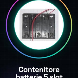
- 🔋 1x Li-ion 18650 Battery (3.7V 2200mAh or higher)
- 🔋 18650 Battery Holder
- 📈 1x Module LM2577 Step-Up
- 🔌 DC Jack Connector (or optional USB step-down connector)
- 🔧 1x Trimmer (already integrated in the module)
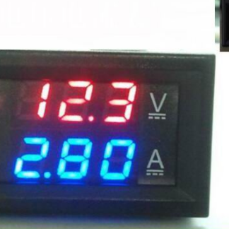
- 💡 Optional Digital Voltmeter (to display voltage)
- 🔋 Optional TP4056 Battery Charging Module (recommended)
- 🧰 Cables, soldering iron, plastic container
🛠️ Construction Phases
✅ 1. Battery Connection
- Connect the battery to the LM2577 module:
B+→IN+B−→IN−
✅ 2. Output Voltage Adjustment
- Power the module and turn the trimmer to to get the desired voltage at the output (e.g., 9V, 12V, 24V…).
- Use a multimeter on the pins
OUT+eOUT−to adjust.
✅ 3. Voltmeter Installation (Optional)
- Connect a small voltmeter between
OUT+eOUT−to monitor the set voltage in real-time.
✅ 4. Mounting in Cases
- Insert the module, battery, and voltmeter into a plastic box or 3D-printed case.
- Install an output jack or USB step-down (type 7805 or AMS1117) to charge 5V devices.
🛡️ Safety
- Do not exceed 3A of load!
- If using Li-ion batteries, include a BMS protection or use protected batteries.
- Add a switch between the battery and the module for safety.
- If you want to recharge the battery, insert a TP4056 module between the power supply and the battery.
🧪 Final Test
- Adjust the voltage.
- Connect a test load (e.g., a LED strip, an Arduino, a motor module).
- Monitor the behavior to avoid overheating.
|
GENERAL |
MODEL |
DC-DC LM2577 |
|
MATERIALS |
pcb + components |
|
|
COMPATIBILITY |
ARDUINO |
|
|
ELECTRICAL COMPONENTS |
INPUT VOLTAGE |
3.5 – 35 V |
|
WEIGHT AND DIMENSIONS |
PRODUCT WEIGHT |
5g |
|
PACKAGE WEIGHT |
0.077 kg |
|
|
PRODUCT DIMENSIONS (L x W x H) |
4.6 X 2.5 X 2 cm |
|
|
PACKAGE DIMENSIONS (Lx W x H) |
5x 3 x 3 cm | |
| PACKAGE CONTENTS |
1 x Module |
Tutorial: How to Use DC-DC Converter LM2577 Step Up
The variable DC-DC LM2577 step up converter is ideal for anyone who wants to power devices that require an output voltage higher than the input voltage. This component is particularly useful for Arduino projects and other electronic systems.
What you need
- Variable DC-DC LM2577 Step Up Converter
- Arduino Uno or similar
- 3-pin header connectors
- Resistors
- Capacitors
Steps
- Check the input and output voltage requirements of your project.
- Connect the converter to the Arduino circuit using the 3-pin header connectors.
- Add resistors for feedback control according to the LM2577 datasheet specifications.
- Insert the necessary capacitors as filter and voltage stabilization.
- Check all connections before powering the circuit.
- If everything is in order, apply the input voltage to the LM2577 DC-DC converter.
- Monitor the output with a multimeter to ensure it meets your requirements.
- Adjust the feedback resistor if necessary.
Mini project
Create an LED lighting system controlled by Arduino powered by the LM2577 converter. Set different brightness levels and change the input voltage to see how the circuit reacts.
Common mistakes
- Do not verify the datasheet specifications before installation.
- Incorrect capacitor connections causing voltage instability.
- Omission of the necessary feedback resistors.
- Incorrect or insufficient power supply for the LM2577 converter.
Recommended accessories
- 3-pin connector
- 10uF electrolytic capacitor
- 1kOhm resistor
- Multimeter
Frequently asked questions
What is the minimum input voltage?
Check the datasheet of the LM2577.
How to adjust the output voltage?
Adjust the feedback resistors according to the datasheet specifications.
Can it power a low current circuit?
Yes, but check the maximum current required by your project.
Reviews
There are no reviews yet.