 EN
 IT Italiano
 ES Español
 FR Français
 DE Deutsch
Description
Technical Description
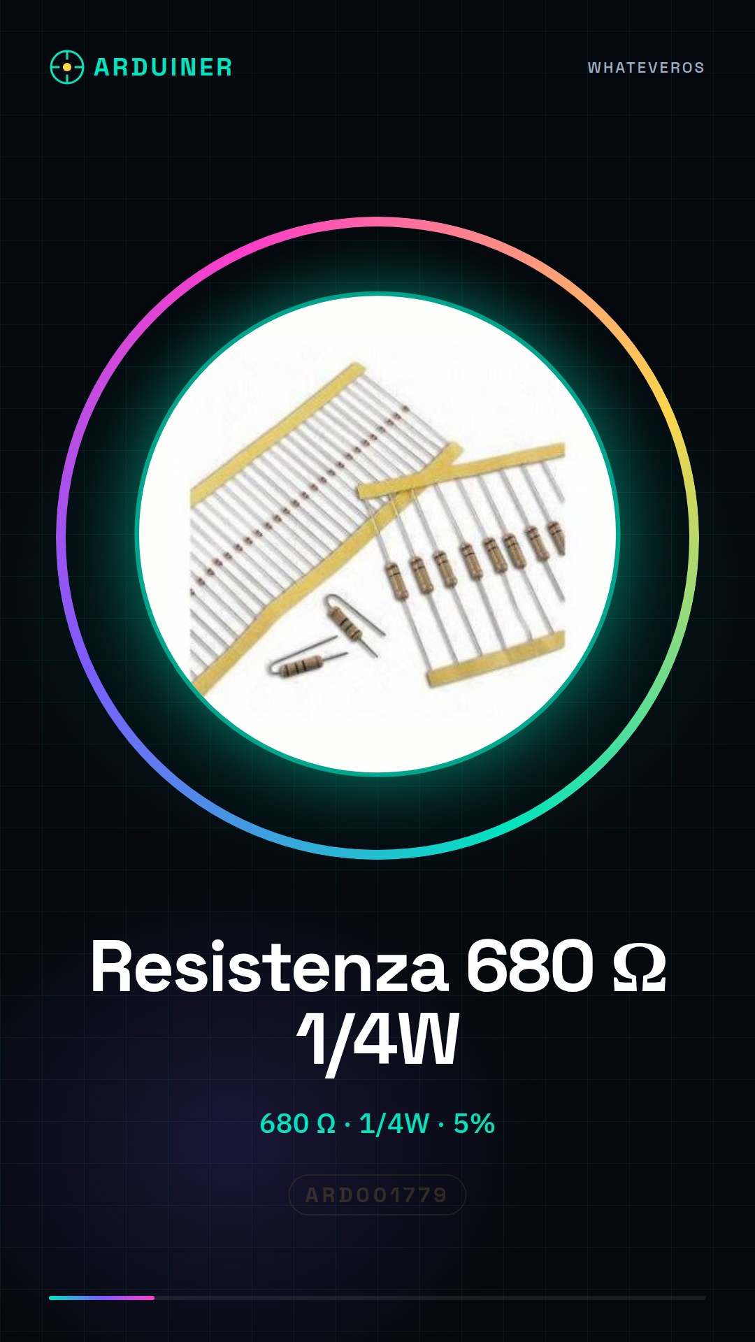
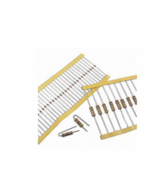
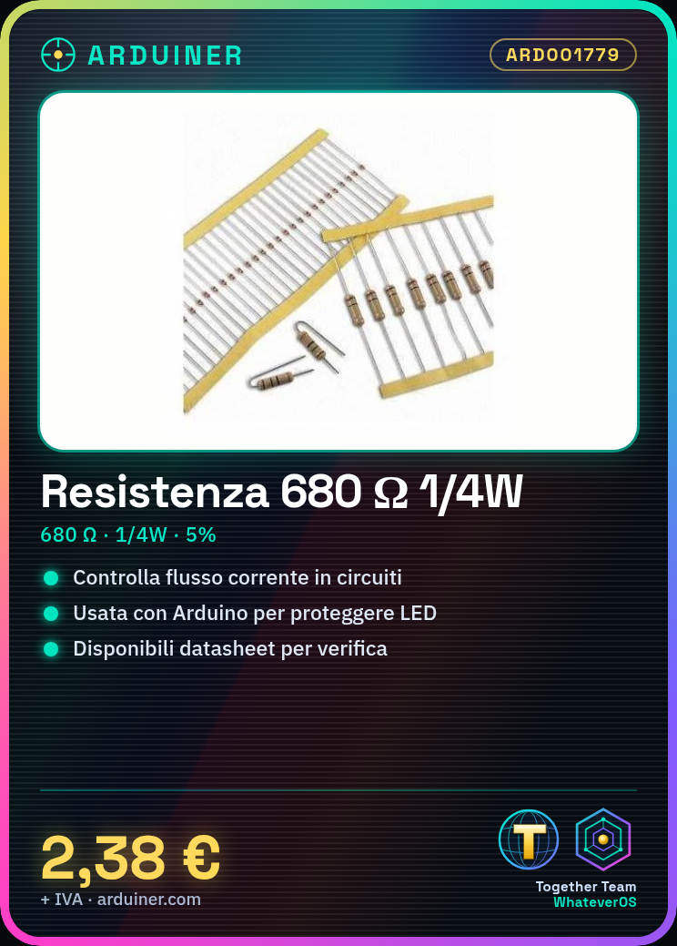
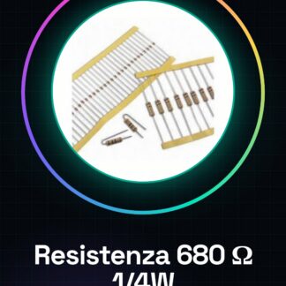
The 680 ohm 1/4w 5% resistor is a fundamental component for limiting the flow of current in an electronic circuit. This resistor, with a 5% tolerance, is suitable for projects that require current control or voltage level division.
The resistor can be used in various electronic projects, such as prototypes, test circuits, and automation applications. Its 1/4 Watt power rating makes it suitable for applications that do not require high heat dissipation.
To ensure proper operation, it is important to verify the resistor’s value with a multimeter before using it in the circuit.
Key Specifications
| Parameter | Value |
| Model | Resistence 680 ohm 1/4w 5% |
| Quantity | 50 pieces |
| Resistive Value | 680 ohm |
| Tolerance | 5% |
| Maximum Power | 1/4 Watt |
| Dimensions | N/D (see manufacturer’s technical sheet) |
| Container | N/D (see manufacturer’s technical sheet) |
Installation and Usage
- Check the resistance value with a multimeter.
- Connect the red end of the connector to the red pole (anode) of an LED.
- Connect the other end of the LED to the resistor.
- Connect the other pole of the resistor to one of the Arduino’s output pins.
- Check the voltage on the connected pin to ensure it does not exceed the device’s maximum limits (check the datasheet).
Compatibility and Requirements
- The resistor is compatible with Arduino and other electronic systems.
- A multimeter is required to verify the resistance value.
- A breadboard is required for circuit prototyping.
- A Dupont connector is required to connect the components.
Limitations and Important Notes
- The resistor is not suitable for applications requiring high heat dissipation.
- The resistor is not suitable for voltages higher than those specified.
- The resistor is not suitable for circuits requiring precision higher than 5%.
- The resistor is not suitable for applications requiring more than 1/4 Watt power.
Troubleshooting
The LED does not light up.
Probable cause: The resistor may have a value different from the specified one.
Solution: Check the resistor value with a multimeter and ensure it is correct.
The voltage on the pin exceeds the device’s maximum limits.
Probable cause: The resistor may not be adequate to limit the current flow.
Solution: Choose a resistor with a more suitable value for the circuit.
The resistor overheats.
Probable cause: The resistor may be subjected to a voltage higher than that specified.
Solution: Check the voltage on the circuit and ensure it does not exceed the resistance limits.
The resistance is burned.
Probable cause: The resistance might be subjected to a current higher than the specified value.
Solution: Check the current on the circuit and ensure it does not exceed the resistance limits.
Use cases
Arduino Project
Objective: Control the current and divide voltage levels.
What you need: 680 ohm 1/4w 5% resistor, Arduino Uno, LED, breadboard, Dupont connector.
Steps: 1) Check the value of the resistor with a multimeter. 2) Connect the resistor to the circuit. 3) Check the voltage on the connected pin.
Expected result: The circuit works correctly.
Electronics Lab
Objective: Test the resistance.
What you need: 680 ohm 1/4w 5% resistor, multimeter.
Steps: 1) Check the value of the resistor with a multimeter.
Expected result: The resistance value is in accordance with the specifications.
Circuit prototyping
Objective: Verify the circuit’s functionality.
What’s needed: 680 ohm 1/4w 5% resistor, breadboard, Dupont connector.
Steps: 1) Connect the resistor to the circuit. 2) Check the voltage at the connected pin.
Expected result: The circuit functions correctly.
Electronics School
Objective: Teach the functioning of resistors.
What’s needed: 680 ohm 1/4w 5% resistor, multimeter, breadboard.
Steps: 1) Check the resistance value with a multimeter. 2) Connect the resistor to the circuit. 3) Check the voltage at the connected pin.
Expected result: Students understand the functioning of resistors.
Maintenance of electronic circuits
Objective: Replace a damaged resistor.
What’s needed: 680 ohm 1/4w 5% resistor, multimeter.
Steps: 1) Check the value of the damaged resistor with a multimeter. 2) Replace the damaged resistor with a new 680 ohm 1/4w 5% resistor.
Expected result: The circuit works correctly.
Electronic circuit repair
Objective: Replace a damaged resistor.
What you need: 680 ohm 1/4w 5% resistor, multimeter.
Steps: 1) Check the value of the damaged resistor with a multimeter. 2) Replace the damaged resistor with a new 680 ohm 1/4w 5% resistor.
Expected result: The circuit works correctly.
Home automation
Objective: Control the current in a home automation circuit.
What you need: 680 ohm 1/4w 5% resistor, Arduino Uno, LED, breadboard, Dupont connector.
Steps: 1) Check the value of the resistor with a multimeter. 2) Connect the resistor to the circuit. 3) Check the voltage on the connected pin.
Expected result: The automation circuit works correctly.
Electronic circuit testing
Objective: To verify the circuit’s functionality.
What you need: 680 ohm 1/4w 5% resistor, multimeter, breadboard.
Steps: 1) Check the resistance value with a multimeter. 2) Connect the resistor to the circuit. 3) Check the voltage on the connected pin.
Expected result: The circuit works correctly.
In the package
- 50 pieces
Complete the project
- 50 Pieces 0.680 ohm 1/4w 1/4 w 5%: Used to verify the resistance value.
Technical FAQs
What is the maximum power it can handle?
The resistor has a power rating of 1/4 Watt, check the datasheet for precise specifications.
Can I use this resistor with another voltage?
Yes, but make sure the resistor does not exceed its thermal capacity limits.
How do I verify the resistance value?
Use a multimeter to check the value of the resistor.
What are the temperature limits for the resistor?
Check the temperature limits on the manufacturer’s datasheet.
Tutorial: How to use 680 ohm Resistor
Resistors are essential for limiting the flow of current in an electronic circuit. This 680 ohm resistor is ideal for Arduino projects where current control or voltage division is needed.
What you need
- Arduino
- Breadboard
- Connectors
- Multimeter
Steps
- Check the value of the resistor with a multimeter.
- Connect the red end of the connector to the red pole (anode) of an LED and the other end to the resistor.
- Connect the other pole of the resistor to one of the Arduino’s output pins.
- Check the voltage on the connected pin to ensure it does not exceed the maximum limits of the device (check on the datasheet).
Mini project
Create a simple circuit where an LED alternately turns on and off every second, using a 680 ohm resistor to control the current flow.
Common mistakes
- Do not check the voltage on the pin.
- Connect the anode of the LED directly to the Arduino pin without protection.
- Use a resistor with an inadequate value that does not adequately limit the current flow.
- Do not use a multimeter to check the value of the resistor.
Recommended accessories
- LED
- Breadboard
- Dupont Connector
- Arduino Uno
Frequently asked questions
What is the maximum power it can handle?
The resistor has a power rating of 1/4 Watt, check the datasheet for precise specifications.
Can I use this resistor with another voltage?
Yes, but make sure the resistor does not exceed its thermal capacity limits.

Reviews
There are no reviews yet.