 EN
 IT Italiano
 ES Español
 FR Français
 DE Deutsch
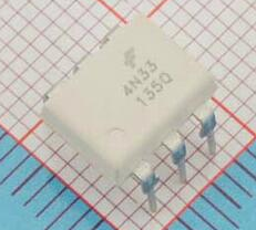
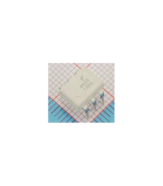
Description
Tutorial: How to use the 4N33 DIP-6 Optoisolator The 4N33 optoisolator is a crucial component for protecting sensitive circuits from electrical interference or damage due to high current voltages. It’s ideal for beginners who want to learn about galvanic isolation between two circuits. What you need: Arduino Uno, Red LED, 220 Ohm Resistor, Test Leads Steps Connect the test leads to the Arduino board using the following pins: VCC to 5V, GND to GND. Connect the red LED output to digital pin 2 of the Arduino and a 220 Ohm resistor between the LED and the digital port. Connect the optoisolator data pins as follows: IN to 3, OUT to 4. Check all connections to ensure they are correct. Open Arduino IDE and upload the following sketch to your Arduino Uno. Start the program on your computer and observe the behaviour of the red LED when interacting with the optoisolator. Example code void setup() { pinMode(3, INPUT); pinMode(4, OUTPUT); } void loop() { if (digitalRead(3) == HIGH) { digitalWrite(2, HIGH); } else { digitalWrite(2, LOW); } } Mini-project Create a simple alarm system that uses the optoisolator to separate the alarm circuit from the rest of the device. Common mistakes Incorrect connection between IN and OUT pins on the optoisolator. Choosing an inappropriate resistor for LED protection. Using voltage higher than the optoisolator’s tolerance. Ignoring verification of connections before testing. Recommended accessories Variable resistors, PIR motion sensors, 5V relays Frequently Asked Questions Can the optoisolator be used in low-voltage circuits? Yes, the 4N33 is designed to work with power supplies up to 70V. What are the advantages of using an optoisolator? It protects the circuit from electrical interference and provides galvanic isolation between two parts of a system.
Reviews
There are no reviews yet.