 EN
 IT Italiano
 ES Español
 FR Français
 DE Deutsch
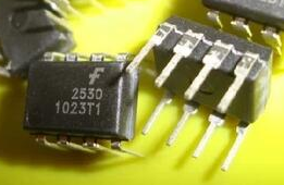
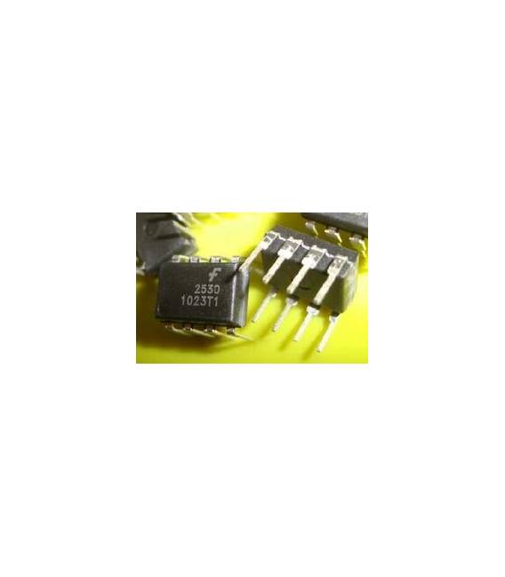
Description
Tutorial: How to Use HCPL-2530
The HCPL-2530 optoisolator is a fundamental component for isolating digital circuits from potentially dangerous electrical loads. Useful for beginners and intermediates working with electrical circuits.
What You Need
Logic Circuit
Electrical Load
Arduino or Microcontroller
Pull-up Resistor
Steps
1. Installation: Place the optoisolator in the circuit, preferably on a PCB.
2. Connect to microcontroller: Connect pin VCC to 5V.
3. Connect to microcontroller: Connect pin GND to ground.
4. Connect to input port: Connect pin IN to a microcontroller pin.
5. Connect to load: Connect pin OUT to the load.
6. Isolation: Check the datasheet for the pull-up resistor value to use between pin OUT and VCC.
7. Test: Upload the example sketch to an Arduino.
8. Verify: Turn on and off the LED connected to OUT and observe the behavior.
Example Code
“`void setup() { pinMode(13, OUTPUT); }
void loop() { digitalWrite(13, HIGH); delay(1000); digitalWrite(13, LOW); delay(1000); }
“`
Mini-Project
Create a simple power switch with a button and an LED.
Common Errors
Connecting IN to ground instead of VCC.
Omitting the pull-up resistor.
Connecting OUT directly to an electrical load.
Not checking the datasheet before using the component.
Recommended Accessories
Arduino Uno
1kΩ Pull-up Resistor
LED
Button
Frequently Asked Questions
Why is the optoisolator necessary? To isolate the digital circuit from the electrical load to prevent damage.
What is the maximum voltage on VCC? Check the datasheet.
Can I use a different pull-up resistor? Check the datasheet for the recommended resistance value.
What happens if I don’t connect the pull-up? It may cause undesired operating conditions.
Reviews
There are no reviews yet.