 EN
 IT Italiano
 ES Español
 FR Français
 DE Deutsch
Description
Technical Description
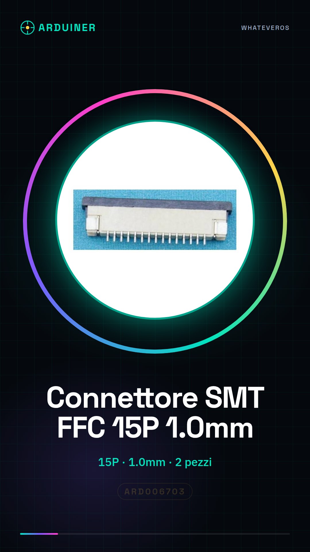
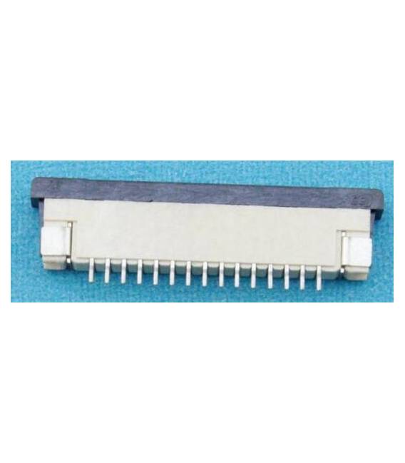
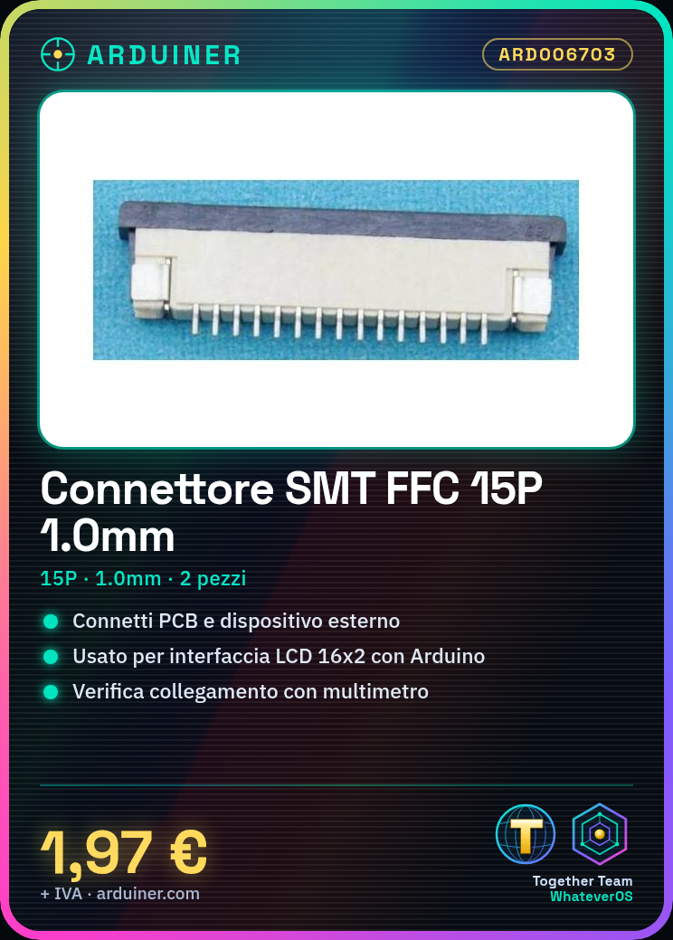
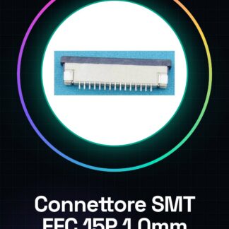
The SMT circuit board connector for flat flexible cable (FFC) 15P 1.0MM is a component used for connecting printed circuits or a circuit to an external device. This type of connector is designed to be applied to printed circuits using surface mount technology (SMT). The FFC connector is suitable for applications requiring flexible and compact connections, such as LCD screens or sensors.
The FFC 15P 1.0MM connector has a pitch of 1.0mm between contacts and can be used to connect compatible flat cables with the same contact layout. Its flexible structure allows managing connections in tight spaces and situations where interface movement is necessary.
To use this connector, you need a ready-to-install SMT printed circuit board and a compatible FFC cable. Soldering must be done carefully to ensure a stable and safe connection.
Key Specifications
| Parameter | Value |
| Model | FFC 15P 1.0MM |
| Number of Contacts | 15 |
| Contact Pitch | 1.0mm |
| Dimensions | N/D (see manufacturer’s datasheet) |
| Connection Type | SMT |
| Container | N/D (see manufacturer’s datasheet) |
| Quantity | 2 pieces |
Installation and Usage
- Check the connector specifications on the datasheet provided by the manufacturer.
- Prepare the printed circuit board where you want to install the connector, ensuring it is clean and ready for SMT installation.
- Use the SMT soldering iron to position the connectors on the printed circuit board according to the datasheet specifications.
- Confirm the correct placement of the connectors using a test kit or an assembly machine.
- Verify the electrical connection with a multimeter, checking that the contacts are soldered correctly.
Compatibility and Requirements
- This connector is compatible with printed circuit boards that use surface mount technology (SMT).
- A compatible FFC cable is required for the connection.
- It can be used with external devices such as LCD screens or sensors.
Limitations and Important Notes
- The FFC 15P 1.0MM connector is not designed for rigid or heavy connections.
- Soldering must be done carefully to avoid short circuits or weak connections.
- Ensure that the FFC cable is compatible with the connector contact layout.
Troubleshooting
Intermittent Connection
Probable Cause: Insufficient or excessive soldering
Solution: Check the soldering with a multimeter and repair any issues.
Damaged Contacts
Probable Cause: Excessive force during installation
Solution: Gently remove the connector and reposition it correctly.
Unstable Connection
Probable Cause: FFC cable not properly inserted
Solution: Verify that the cable is fully and correctly inserted into the connector.
Does not respond to test
Probable Cause: Contacts not soldered correctly
Solution: Check the soldering with a multimeter and repair any issues.
Use cases
Parking sensor for the garage
Objective: Install a distance sensor on a printed circuit board to monitor garage occupancy
What’s needed: FFC cable, printed circuit board, distance sensor
Steps: 1) Check the connector specifications 2) Prepare the printed circuit board 3) Solder the connector 4) Connect the distance sensor 5) Test the connection
Expected result: The distance sensor is correctly connected to the printed circuit board.
LCD interface for an Arduino project
Objective: Connect an LCD screen to a printed circuit board to display data
What’s needed: FFC cable, printed circuit board, LCD screen
Steps: 1) Check the connector specifications 2) Prepare the printed circuit board 3) Solder the connector 4) Connect the LCD screen 5) Test the connection
Expected result: The LCD screen is correctly connected to the printed circuit board.
Heart rate monitoring project
Objective: Connect a heart rate sensor to a printed circuit board
What’s needed: FFC cable, printed circuit board, heart rate sensor
Steps: 1) Check the connector specifications 2) Prepare the printed circuit board 3) Solder the connector 4) Connect the heart rate sensor 5) Test the connection
Expected result: The heart rate sensor is correctly connected to the printed circuit board.
Temperature control project
Objective: Connect a temperature sensor to a printed circuit board
What’s needed: FFC cable, printed circuit board, temperature sensor
Steps: 1) Check the connector specifications 2) Prepare the printed circuit board 3) Solder the connector 4) Connect the temperature sensor 5) Test the connection
Expected result: The temperature sensor is correctly connected to the printed circuit board.
Light control project
Objective: Connect a light sensor to a printed circuit board to regulate lighting
What’s needed: FFC cable, printed circuit board, light sensor
Steps: 1) Check the connector specifications 2) Prepare the printed circuit board 3) Solder the connector 4) Connect the light sensor 5) Test the connection
Expected result: The light sensor is correctly connected to the printed circuit board.
Noise monitoring project
Objective: Connect a noise sensor to a printed circuit board
What’s needed: FFC cable, printed circuit board, noise sensor
Steps: 1) Check the connector specifications 2) Prepare the printed circuit board 3) Solder the connector 4) Connect the noise sensor 5) Test the connection
Expected result: The noise sensor is correctly connected to the printed circuit board.
Pressure Monitoring Project
Objective: Connect a pressure sensor to a printed circuit board
What’s needed: FFC cable, printed circuit board, pressure sensor
Steps: 1) Check the connector specifications 2) Prepare the printed circuit board 3) Solder the connector 4) Connect the pressure sensor 5) Test the connection
Expected result: The pressure sensor is correctly connected to the printed circuit board.
Motion Monitoring Project
Objective: Connect a motion sensor to a printed circuit board
What’s needed: FFC cable, printed circuit board, motion sensor
Steps: 1) Check the connector specifications 2) Prepare the printed circuit board 3) Solder the connector 4) Connect the motion sensor 5) Test the connection
Expected result: The motion detector is correctly connected to the printed circuit board.
In the package
- 2 pieces
Complete the project
- 2 Pieces SMT Circuit Board Connector for Flat Cable FFC 30P 1.0MM: To connect the FFC 15P 1.0MM connector to a compatible flat cable.
- 2 Pieces SMT Circuit Board Connector for Flat Cable FFC 15P 0.5MM: To test the electrical connection of the FFC 15P 1.0MM connector.
- Flexible Flat Cable FFC/FPC 15P 1.0 Pitch 200CM A-B Cable: To connect the FFC 15P 1.0MM connector to a printed circuit board via surface mount technology (SMT).
Technical FAQs
How can I verify if the connector has been installed correctly?
Use a multimeter to check the continuity between the connector contacts.
Can I use this connector with other types of FFC flat cables?
Check the datasheet for the connector and FFC cable specifications to ensure compatibility.
What tools are needed for installation?
Test kit, SMT soldering iron, and digital multimeter.
What are the usage limitations of this connector?
It is not designed for rigid or heavy connections and soldering must be done with care.
Tutorial: How to use SMT FFC 15P 1.0MM Connector
This SMT circuit board connector for FFC (Flat Flexible Cable) is ideal for projects requiring a connection between two circuit boards or between a circuit and an external device, such as LCD screens or detectors. It is particularly useful for technology enthusiasts who want to create smaller and lighter devices.
What you need
- Compatible FFC cable
- SMT soldering iron
- Test kit
Steps
- Check the datasheet for the connector specifications, such as contact layout and impedance type.
- Prepare the printed circuit board where you want to install the connector, ensuring it is clean and ready for SMT installation.
- Use the SMT soldering iron to position the connectors on the printed circuit board according to the datasheet specifications.
- Confirm the correct placement of the connectors using a test kit or an assembly machine.
- Verify the electrical connection with a multimeter, checking that the contacts are soldered correctly.
- If necessary, apply a protective coating to the printed circuit board to protect the SMT connector.
Mini project
Create a small interface with an Arduino and a 16×2 LCD screen. Connect the LCD screen using this FFC connector.
Common mistakes
- Incorrect placement of connectors
- Insufficient or excessive soldering
- Incorrect FFC cable connection
Recommended accessories
- Test kit
- SMT soldering iron
- Digital multimeter
- Compatible flat FFC cable
Frequently asked questions
How can I verify if the connector has been installed correctly?
Use a multimeter to check continuity between the connector contacts.
Can I use this connector with other types of flat FFC cable?
Check the datasheet for the connector specifications and the type of cable it supports.
Reviews
There are no reviews yet.