 EN
 IT Italiano
 ES Español
 FR Français
 DE Deutsch
Description
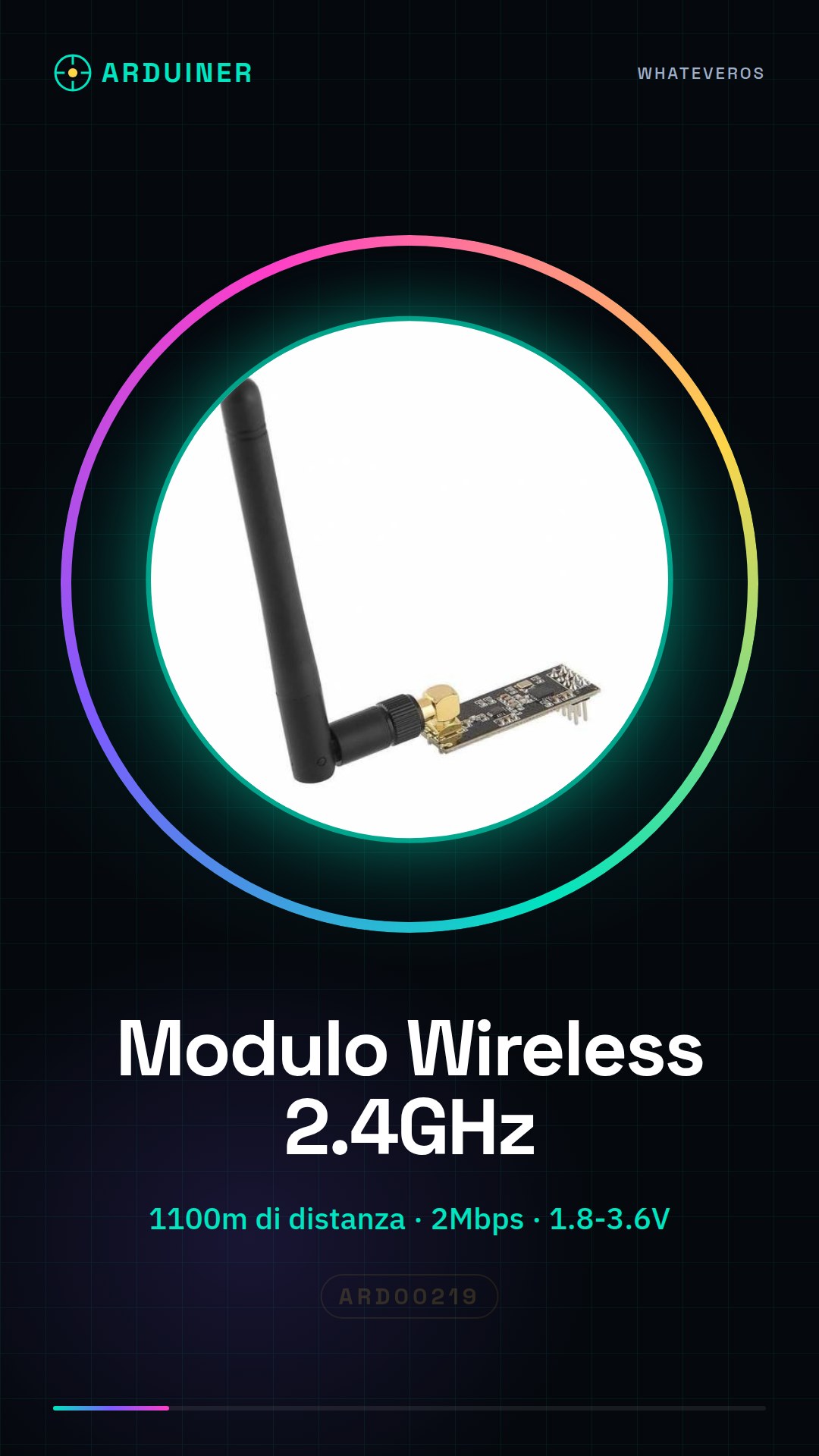
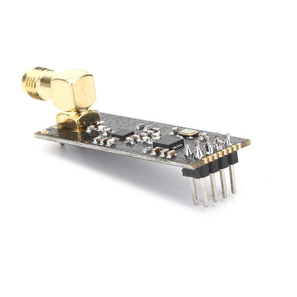
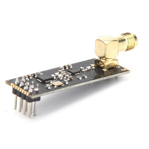
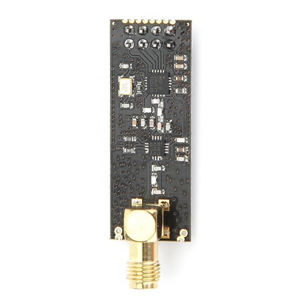
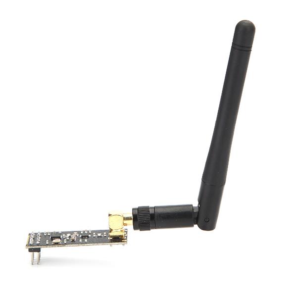
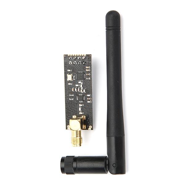
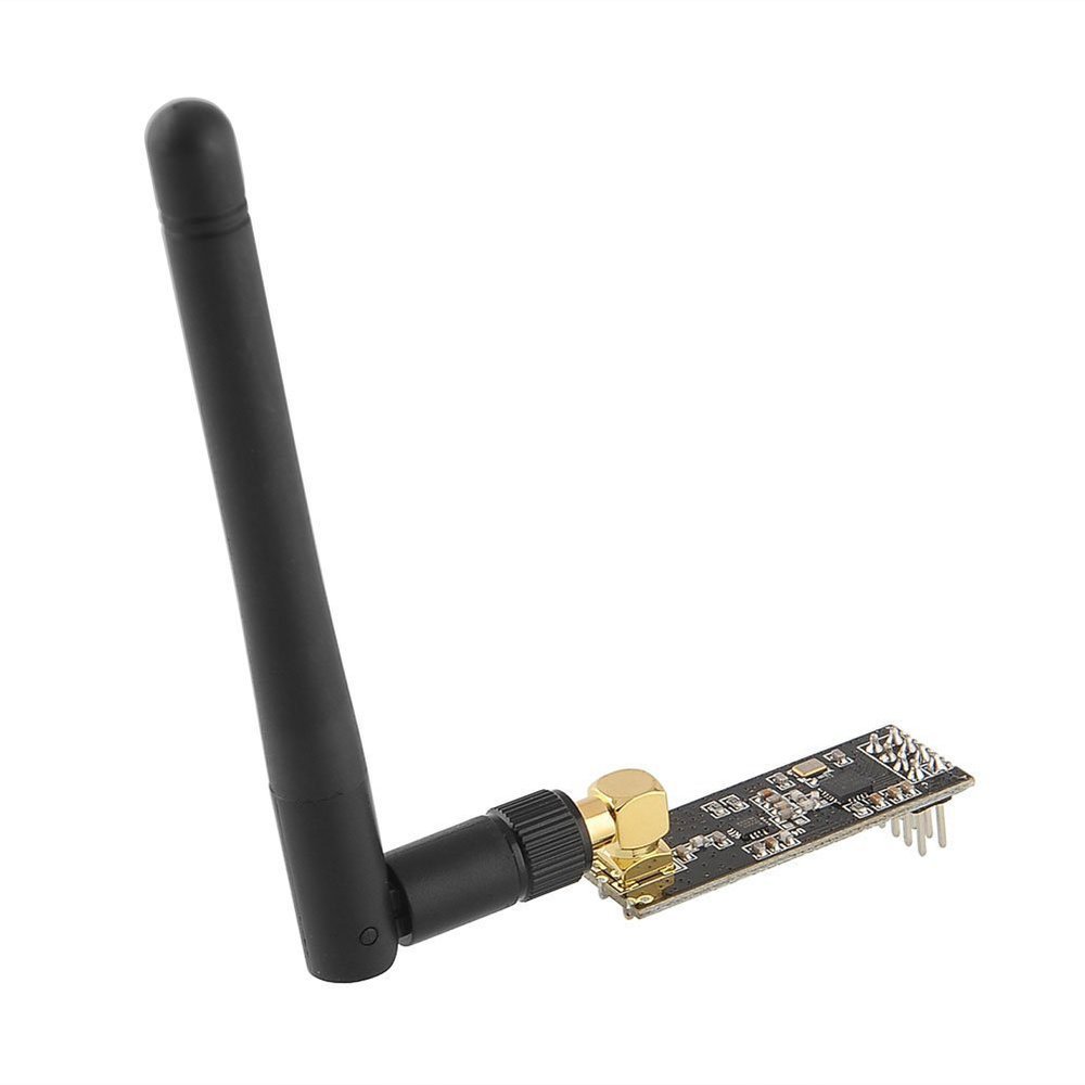
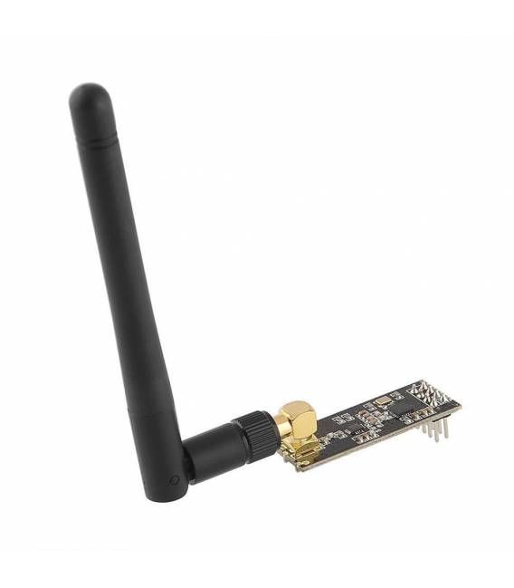
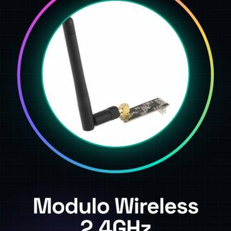
Wireless Module 2.4GHz NRF24L01 + PA + LNA with SMA Antenna MCU Long Range 1100 meters
Wireless module for long-range data transmission (up to 1100m) on the 2.4GHz frequency with a maximum transmission speed of up to 2Mbps. The module guarantees excellent wireless communication performance with the integrated Enhanced ShockBurst protocol, designed for low-power applications. The FIFO operating mode ensures a regular data flow between the module and the MCU system. The integrated PCB antenna allows power transmission up to 100mW. Communication occurs via 4-wire SPI at a speed of up to 10Mbps, compatible with various microprocessors MCU/ARM/PIC/AVR/STM32 and development kits such as Arduino. It is widely used in industrial settings, security systems, telemetry, and many other applications.
TECHNICAL SPECIFICATIONS:
Model: AS01-ML01DP6 v4.0
Integrated antenna on PCB for communication up to 1100m
Supply voltage: 1.8 ~ 3.6V
Data transmission speed: 2Mbit/s, 1Mbit/s, 250Kbit/s
4 selectable transmission power levels
Operating frequency: 2.400 ~ 2.525GHz
6 data channels and 126 communication channels in 1MHz steps
Operating current: 13.5mA at 2Mbps / 11.3mA at 0dBm output power
Power-down energy consumption: 400nA
Enhanced CRC checksum control and multi-point addressing, ShockBurst
CONNECTION MODES:
1.GND 2. 3V3
3. CE 4. CSN
5. SCN 6. MOSI
7. MISO 8.IRQ
Connection strip pitch: 2.54mm
Module dimensions: 30 x 17 mm
We have datasheets available for all components, if not present in the product download card, send us a message through the contact us form and we will publish it as soon as possible.
Tutorial: How to use NRF24L01 + PA + LNA Module
The NRF24L01 + PA + LNA module is ideal for creating stable and long-range wireless connections between Arduino devices. It is used to transmit data over 2.4GHz with a range up to 1100 meters.
What you need
- Arduino Uno or compatible
- NRF24L01 + PA + LNA module
- SMA antenna cable
Steps
- Connect the NRF24L01 module to the corresponding pins of the Arduino: VCC, GND, CE, CSN, SCK, MISO, MOSI.
- Check the connection between the SMA antenna and the module.
- Install the RF24 library through the Arduino Library Manager.
- Configure the NRF24L01 module pins in the code.
- Set the RX and TX pipes for bidirectional communication.
- Initialize the module with the begin() function.
- Configure the transmission and reception address.
- Test data transmission between two Arduinos connected via NRF24L01.
Example code
// Includi la libreria RF24
#include <RF24.h>
// Definisci i pin del modulo
const int CE_PIN = 9;
const int CSN_PIN = 10;
// Crea un oggetto RF24
RF24 radio(CE_PIN,CSN_PIN);
void setup() {
radio.begin();
radio.openWritingPipe(0xF0F0F0F0E1LL); // Imposta la pipe di trasmissione
radio.openReadingPipe(1, 0xF0F0F0F0D2LL); // Imposta la pipe di ricezione
}
Mini project
Create a home security system that sends wireless notifications to a central console when movements or sounds are detected.
Common mistakes
- Do not properly verify physical connections.
- Incorrectly set the RX and TX pipes.
- Ignore the module channel configuration.
- Use inadequate power supplies for the module.
Recommended accessories
- External SMA antenna
- SMA connection cable
- Arduino Nano
- PIR sensors
Frequently asked questions
How can I increase the range?
Use a more powerful antenna and connect it to the module via an SMA cable.
What is the power consumption of the module?
Check the datasheet for specific power consumption details.
Reviews
There are no reviews yet.