 EN
 IT Italiano
 ES Español
 FR Français
 DE Deutsch
Description
Technical Specifications
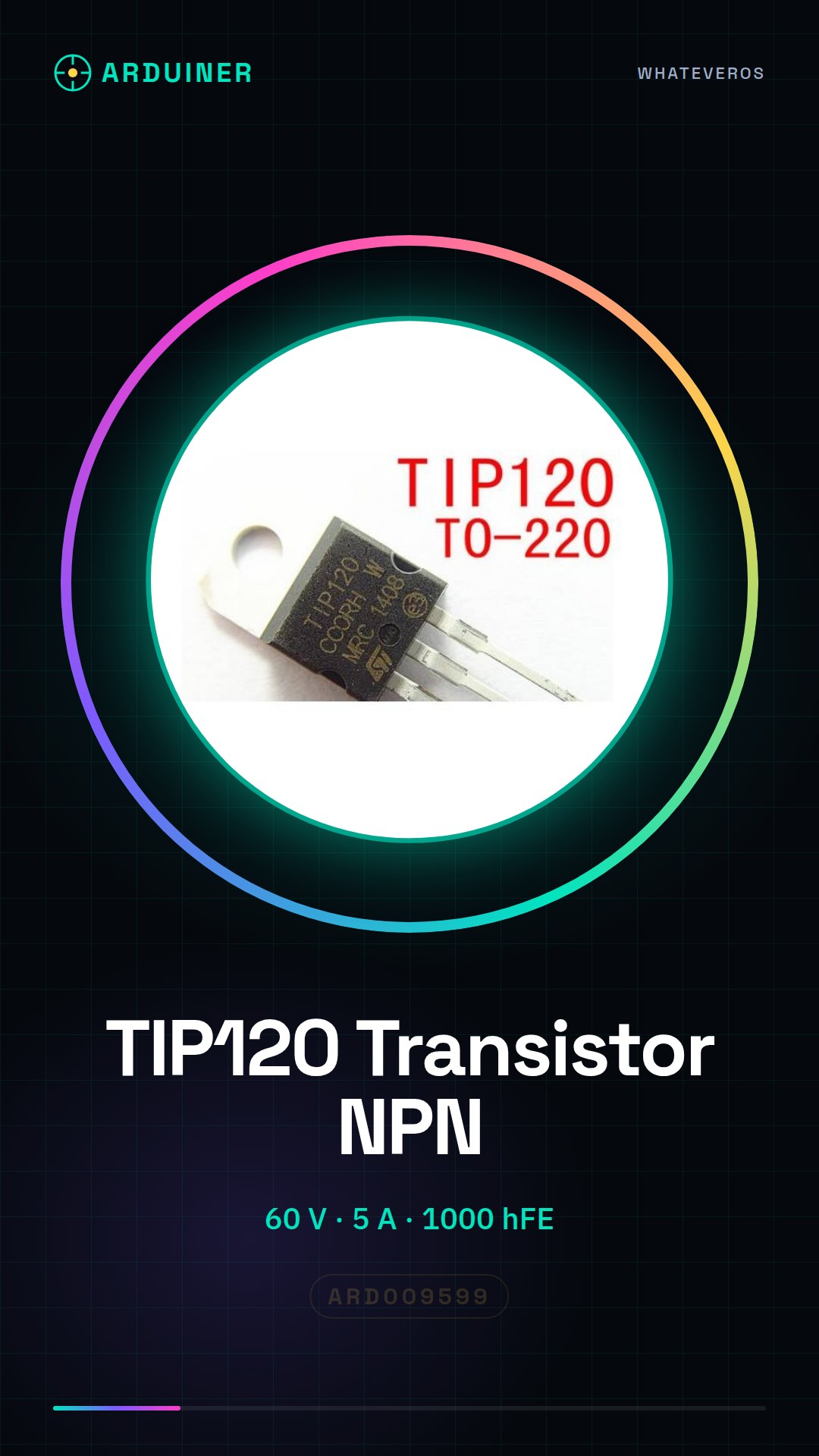
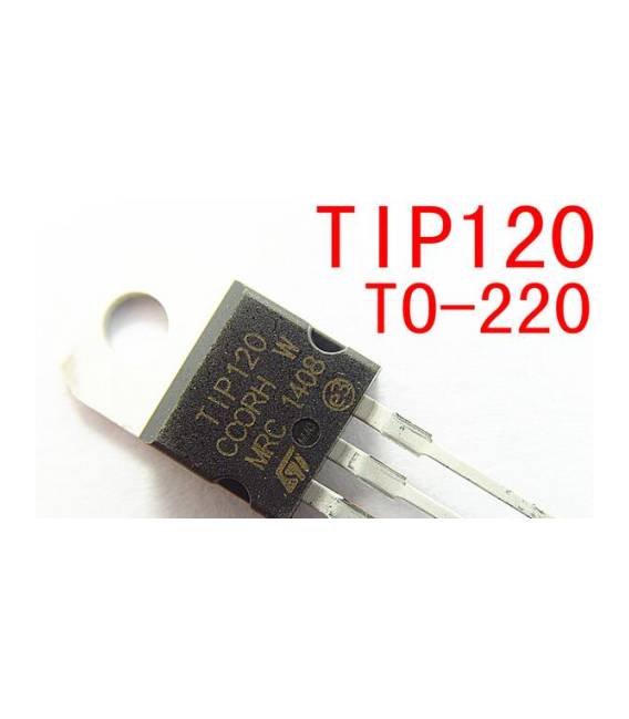
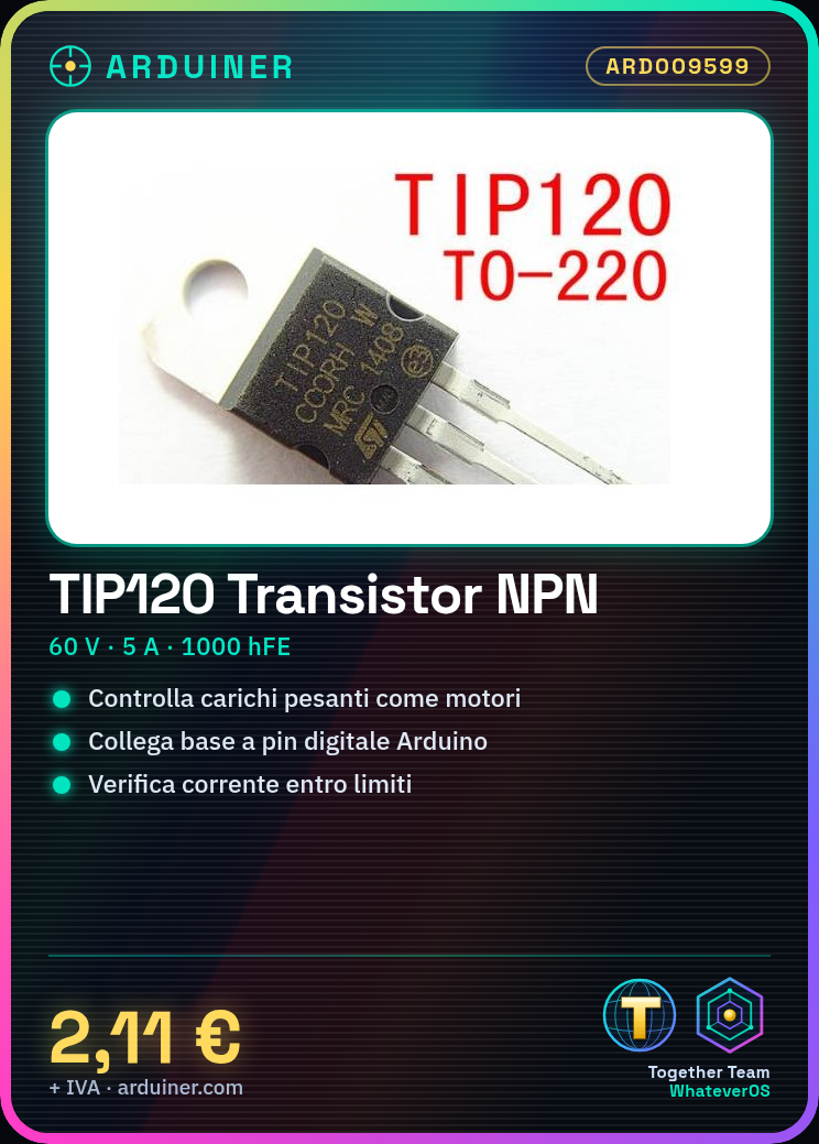
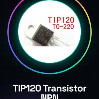
The TIP120 is a single bipolar junction transistor (BJT) of the NPN type designed for high-power applications. With a maximum base-emitter voltage of 60V and a maximum power dissipation of 65W, the TIP120 is suitable for controlling heavy loads such as motors and relays. Its ability to handle a maximum current of 5A makes it a versatile component for electronic projects.
The TIP120 transistor functions as an electronic switch, allowing the control of loads that require electrical currents higher than those that can be directly provided by microcontrollers like Arduino. It is important to verify that the load current and voltage are within the limits specified by the TIP120 datasheet to ensure safe and efficient use.
For proper use, it is necessary to correctly connect the base, emitter, and collector of the TIP120 with respect to the power supply and the load to be controlled. Checking the current flow is essential to avoid damage to the component.
Key Specifications
| Parameter | Value |
| Model | TIP120 |
| Type | Single Bipolar Transistor (BJT) |
| Polarity | NPN |
| Maximum Base-Emitter Voltage | 60 V |
| Maximum Power Dissipation | 65 W |
| Maximum Current | 5 A |
| hFE (Current Gain) | 1000 |
| Package | TO-220 |
Installation and Usage
- Connect the base of the TIP120 to a digital pin of the Arduino.
- Connect the emitter to the negative (-) power supply rail.
- Connect the collector to the positive (+) side of the load to be controlled.
- Check the load current against the limits of the TIP120.
- Write a simple Arduino sketch to turn the load on and off.
Compatibility and Requirements
- The TIP120 is compatible with Arduino and other microcontrollers with digital I/O pins.
- It is suitable for controlling heavy loads such as motors and relays.
- To use it, you need a power supply and a load to control.
Limitations and Important Notes
- The TIP120 is not designed for low-power applications.
- It is important to verify that the load voltage and current are within the specified limits.
- Do not use the TIP120 without a proper connection to ground.
- Do not connect the power directly to the load without the TIP120 in between.
Troubleshooting
The load does not turn on.
Probable cause: The current exceeds the TIP120 limits.
Solution: Check the load current and reduce if necessary.
The TIP120 overheats.
Probable cause: The power dissipation exceeds the component limits.
Solution: Check the power dissipation and reduce the current if necessary.
The TIP120 does not work as expected.
Probable cause: The ground connection is incorrect.
Solution: Check the emitter ground connection.
The load turns on but does not turn off completely.
Probable cause: The hFE value is too low.
Solution: Check the TIP120 hFE value and replace if necessary.
Use cases
Home automation
Objective: Control a motor for an irrigation system.
What is needed: TIP120, Arduino, motor, power supply.
Steps: 1) Connect the TIP120 between Arduino and motor. 2) Check the motor current. 3) Write an Arduino sketch to control the motor.
Expected result: The motor is controlled by Arduino.
Prototyping Lab
Objective: Test the TIP120 with a heavy load.
What’s needed: TIP120, Arduino, relay, power supply.
Steps: 1) Connect the TIP120 between Arduino and relay. 2) Check the relay current. 3) Write an Arduino sketch to test the TIP120.
Expected result: The relay is controlled by Arduino through the TIP120.
Electronic Systems Maintenance
Objective: Repair a damaged circuit.
What’s needed: TIP120, Arduino, multimeter.
Steps: 1) Check the damaged circuit. 2) Replace the damaged component with a TIP120. 3) Test the repaired circuit.
Expected result: The repaired circuit works correctly.
Hobby Electronic Projects
Objective: Control an LED with a heavy load.
What you need: TIP120, Arduino, LED, resistor.
Steps: 1) Connect the TIP120 between Arduino and LED. 2) Check the current of the LED. 3) Write an Arduino sketch to turn the LED on and off.
Expected result: The LED is controlled by Arduino through the TIP120.
Prototype development
Objective: Test the TIP120 with a variable load.
What you need: TIP120, Arduino, variable load, power supply.
Steps: 1) Connect the TIP120 between Arduino and variable load. 2) Check the current of the variable load. 3) Write an Arduino sketch to test the TIP120.
Expected result: The variable load is controlled by Arduino through the TIP120.
Industrial automation projects
Objective: Control a heavy load.
What you need: TIP120, Arduino, heavy load, power supply.
Steps: 1) Connect the TIP120 between Arduino and heavy load. 2) Check the current of the heavy load. 3) Write an Arduino sketch to control the heavy load.
Expected result: The heavy load is controlled by Arduino through the TIP120.
Electronic test projects
Objective: To verify the performance of the TIP120.
What you need: TIP120, Arduino, multimeter, power supply.
Steps: 1) Connect the TIP120 between Arduino and multimeter. 2) Check the current of the multimeter. 3) Write an Arduino sketch to test the TIP120.
Expected result: The performance of the TIP120 is verified correctly.
Educational electronics projects
Objective: To illustrate the operation of the TIP120.
What you need: TIP120, Arduino, LED, resistor.
Steps: 1) Connect the TIP120 between Arduino and LED. 2) Check the current of the LED. 3) Write an Arduino sketch to turn the LED on and off.
Expected result: The operation of the TIP120 is correctly illustrated.
In the package
- 1 piece TIP120 Single Bipolar (BJT), NPN, 60 V, 65 W, 5 A, 1000 hFE
Complete the project
- 6 Pieces 2SC5707 Single Bipolar IC Integrated Circuits: To control heavy loads with Arduino, the TIP120 is a fundamental component.
Technical FAQs
Can the TIP120 control any type of load?
Yes, but make sure the current and voltage are within the transistor’s limits.
What is the minimum hFE value for safe use?
Check the datasheet; generally, an hFE of 1000 is sufficient for many applications.
Why does the TIP120 overheat?
The power dissipated exceeds the component’s limits. Check the power dissipation and reduce the current if necessary.
Why doesn’t the load turn on?
The current exceeds the limits of the TIP120. Check the load current and reduce if necessary.
Tutorial: How to Use TIP120 Bipolar Transistor
The TIP120 is a high-power NPN transistor, ideal for controlling heavy loads such as motors and relays. It is suitable for both Arduino beginners and experts.
What you need
- Arduino
- LED or resistor (for testing)
- jumper wires
Steps
- Connect the base of the TIP120 to a digital pin of the Arduino.
- Connect the emitter to the ground (-) of the power supply.
- Connect the collector to the positive (+) side of the load to be controlled.
- Write a simple Arduino sketch to turn on and off the LED or the connected load.
- Check if the current is within the maximum limits (check the datasheet).
Example code
void setup() {
  pinMode(2, OUTPUT);
}

void loop() {
  digitalWrite(2, HIGH); // Accende il carico
  delay(1000);
  digitalWrite(2, LOW); // Spegne il carico
  delay(1000);
}
Mini project
Control a small motor with Arduino using the TIP120.
Common mistakes
- Use a supply voltage higher than the maximum of the transistor.
- Do not check the current draw before use.
- Omit the connection to ground for the emitter.
- Connect the power directly to the load without the TIP120 in between.
Recommended accessories
- Basic resistors
- 5V relay
- Small motor
Frequently asked questions
Can the TIP120 control any type of load?
Yes, but make sure the current and voltage are within the transistor’s limits.
What is the minimum hFE value for safe use?
Check the datasheet; generally, an hFE of 1000 is sufficient for many applications.
Reviews
There are no reviews yet.