 EN
 IT Italiano
 ES Español
 FR Français
 DE Deutsch
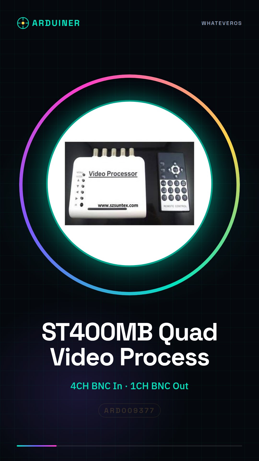
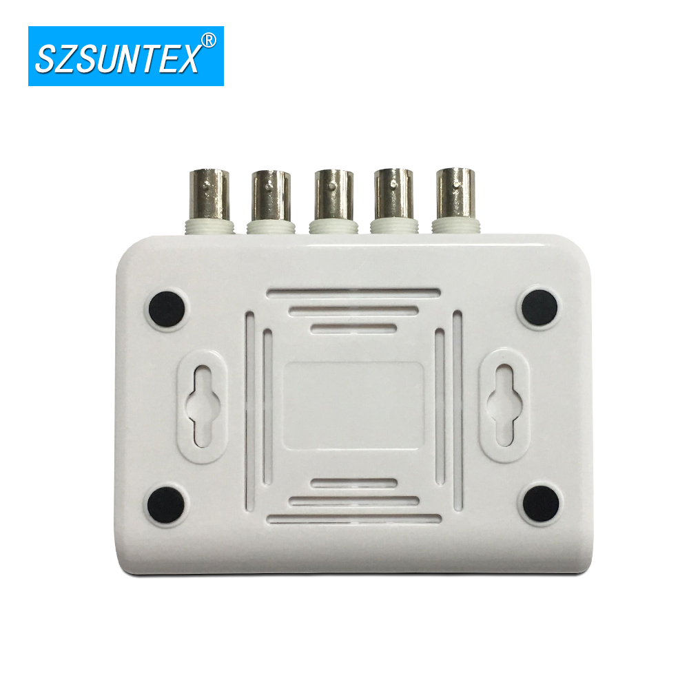
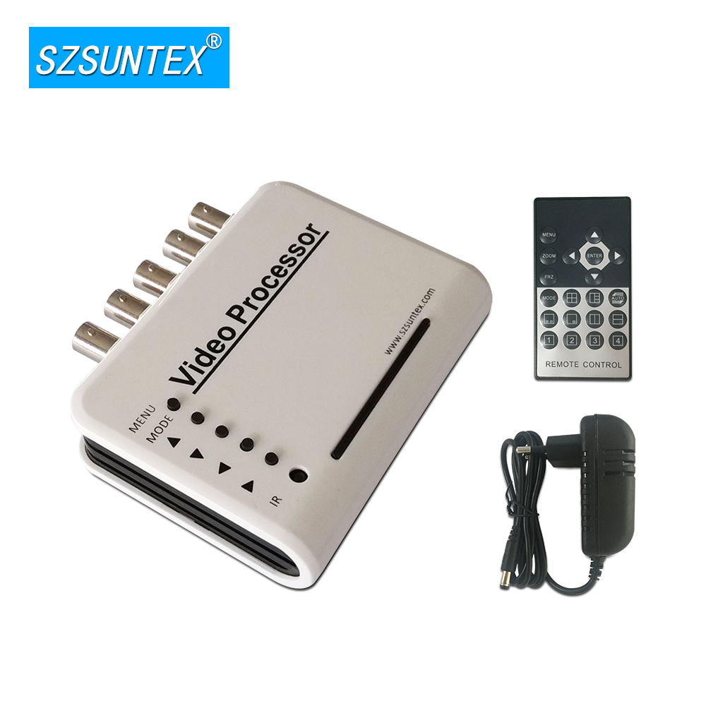
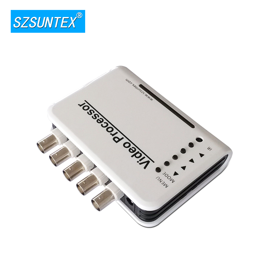
Description
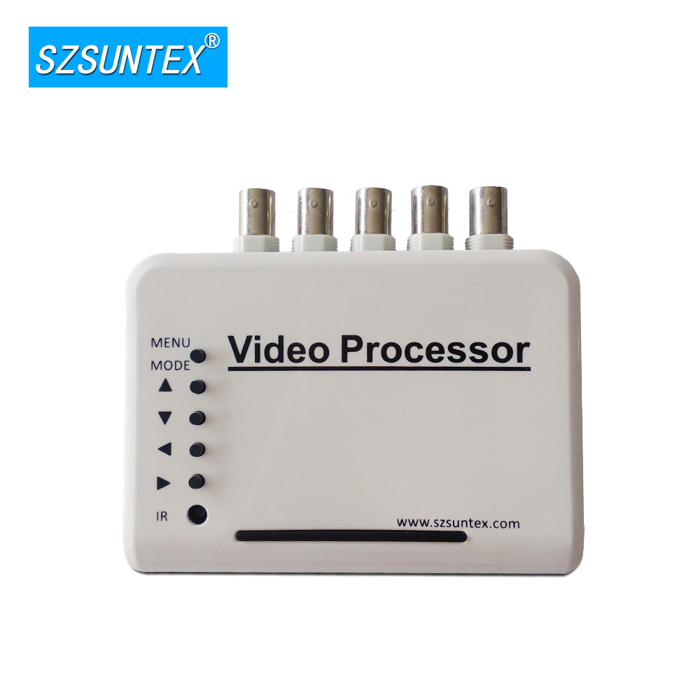
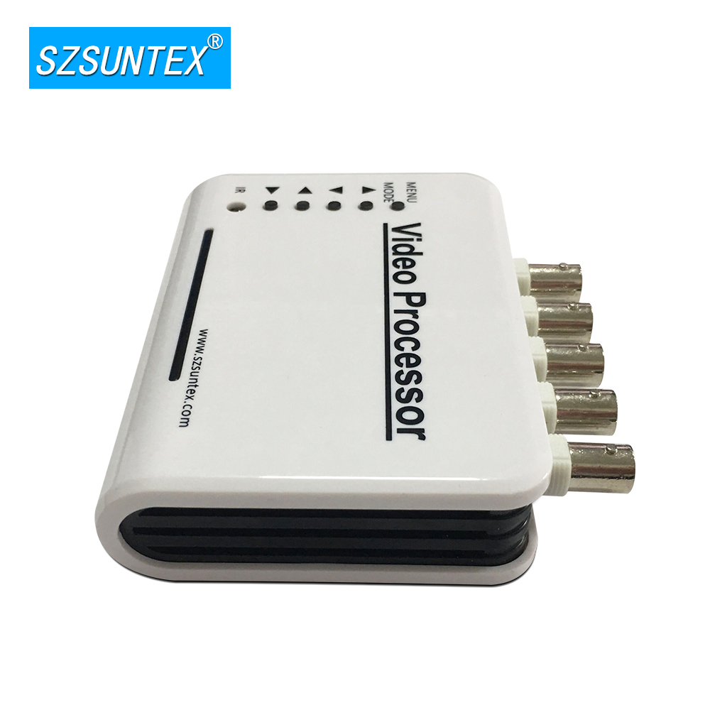
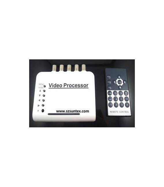
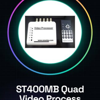
ST400MB Quad Color Video Channel Processor / Video Multiplexer
| Product Name | Quad Color Video Channel Processor / Video Multiplexer | |
| Number of Modes | ST400MB | |
| Image Reconditioning | PAL: 25 f/s; NTSC: 30 f/s | |
| Resolution | PAL: 720 * 576; NTSC: 720 * 480 | |
| Video Input | 4CH BNC 1Vp-p 75 | |
| Video Output | 1CH BNC 1Vp-p 75 | |
| Power Supply | DC 12V | |
| Power Consumption | 2W | |
| Shutdown Memory Function | Support | |
| Various Display Modes | Full Screen, Dual, Quad, PIP, Auto Sequence, etc. | |
| Lock Function | Flicker Free Image Capture | |
| Zoom Function | Selectable Zoom Area | |
| Adjustable Video | Brightness, Contrast, Saturation, Tint, Sharpness Adjustment | |
| Operating Temperature | -30 -60 | |
| Dimensions | 119mm * 90mm * 26mm |
Tutorial: How to Use ST400MB
The ST400MB is a 4-channel color video multiplexer, ideal for connecting multiple image sensors to a single Arduino board. Useful for projects requiring the management of multiple cameras or image sensors.
What you need
- ST400MB
- Arduino
- Connection Cables
- Image sensors
Steps
- Check the datasheet for the ST400MB specifications.
- Connect the VCC of the ST400MB to the 5V of the Arduino.
- Connect the GND of the ST400MB to the GND of the Arduino.
- Connect the S0 and S1 pins of the ST400MB to two digital pins of the Arduino (e.g., 8 and 9).
- Connect the IN0-3 pins of the ST400MB to the respective image sensors.
- Upload the source code to your Arduino.
- Set the S0 and S1 pins to select the correct channel.
- Read the data from the sensors with the source code.
Example code
void setup() {
 pinMode(8, OUTPUT);
 pinMode(9, OUTPUT);
}

void loop() {
 digitalWrite(8, LOW);
 digitalWrite(9, LOW);
 delay(1000);
 digitalWrite(8, HIGH);
 digitalWrite(9, LOW);
 delay(1000);
 digitalWrite(8, LOW);
 digitalWrite(9, HIGH);
 delay(1000);
 digitalWrite(8, HIGH);
 digitalWrite(9, HIGH);
 delay(1000);
}
Mini project
Connecting three image sensors to the ST400MB and sequential selection of channels to display images.
Common mistakes
- Connect the VCC to 3.3V instead of 5V.
- Forget to check the specifications on the datasheet.
- Do not set the S0 and S1 pins correctly.
- Do not read the data from the sensors correctly.
Recommended accessories
- Image sensors
- Connection cables
- Arduino
- ESD protection
Frequently asked questions
How to set pins S0 and S1?
Set them as output and select the desired channel.
Which specifications should be checked in the datasheet?
Check the voltage and current values for VCC and GND, and the pins S0 and S1.
Can I use this multiplexer with an Arduino Uno?
Yes, but make sure the Arduino supports the pins being used.
Reviews
There are no reviews yet.