 EN
 IT Italiano
 ES Español
 FR Français
 DE Deutsch
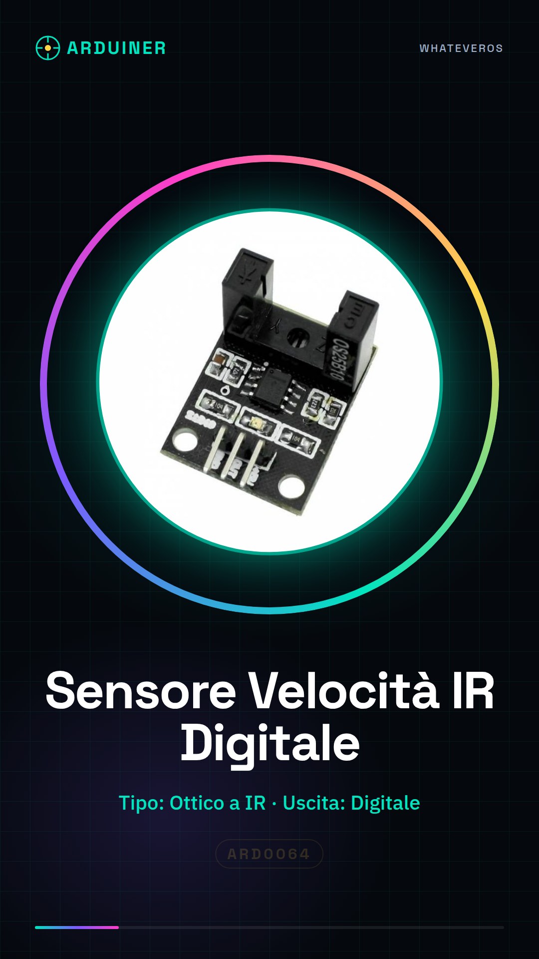
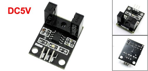
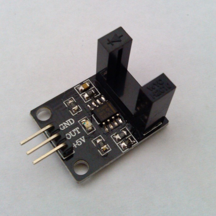
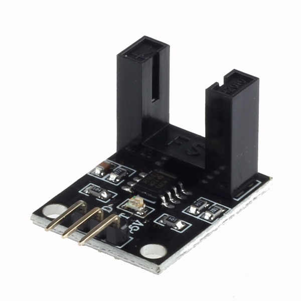
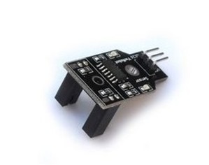
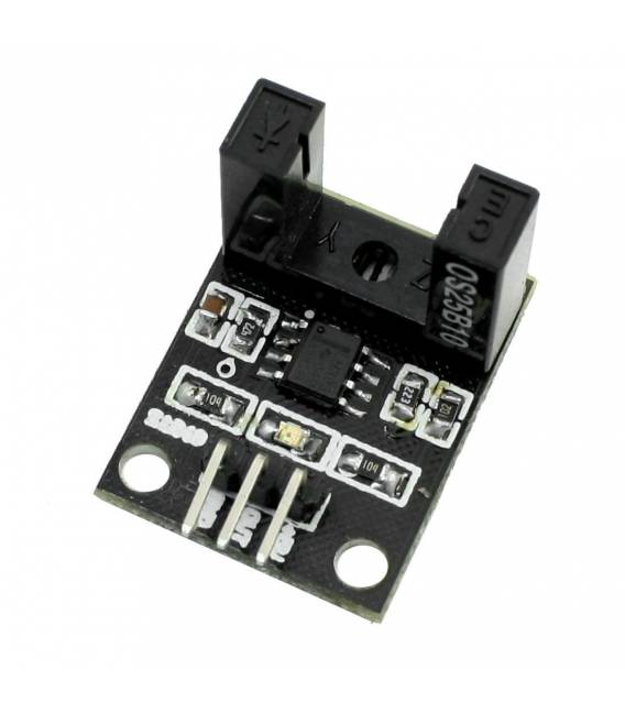
Description
🔍 Description of the Digital IR Speed Sensor Encoder Module
✅ Main Features
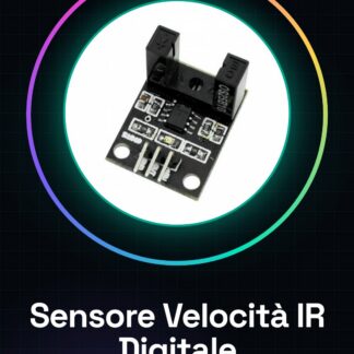
The Digital IR Speed Sensor Module with Encoder is a commonly used device for detecting the rotational speed or counting the rotations of moving objects such as motors or wheels.
- Sensor Type: Infrared Optical
- Output: Digital (0 or 1 logic)
- Principle of Operation: Interruption of an IR beam by a coded disk (encoder disk)
- Operating Voltage: 3.3V – 5V
- Output Type: Digital signal (HIGH/LOW)
- Pin: VCC, GND, OUT
- Supported Frequency: Up to ~1000 RPM (depends on the encoder disk)
🧰 Typical Applications
- Angular speed measurement of motors
- Count pulses (tachometers)
- Robotics and automation
- Optical encoders for robotic wheels
⚙️ Components needed for the Arduino project
- 1x Arduino UNO (or compatible)
- 1x IR Speed Sensor Module
- 1x Encoder Disk (coded wheel, perforated)
- Dupont Cables
- DC Motor (optional)
- Breadboard (optional)
🔌 Electrical Connections
| IR Encoder Module | Arduino |
|---|---|
| VCC | 5V |
| GND | GND |
| OUT | Digital pin (e.g., 2) |
🖥️ Example code for Arduino
1. Pulse reading
volatile int conta_impulsi = 0;

void setup() {
  Serial.begin(9600);
  pinMode(2, INPUT);
  attachInterrupt(digitalPinToInterrupt(2), contaImpulso, RISING);
}

void loop() {
  Serial.print("Impulsi contati: ");
  Serial.println(conta_impulsi);
  delay(1000);
}

void contaImpulso() {
  conta_impulsi++;
}
✅ This sketch uses the interrupt on pin 2 (only pins 2 and 3 support interrupts on Arduino UNO) to count the interrupts generated by the encoder disk.
2. Calculation of angular speed (RPM)
Suppose the disk has 20 holes (20 pulses per full rotation):
volatile int impulsi = 0;
unsigned long tempo_precedente = 0;

void setup() {
  Serial.begin(9600);
  pinMode(2, INPUT);
  attachInterrupt(digitalPinToInterrupt(2), contaImpulso, RISING);
}

void loop() {
  unsigned long tempo_attuale = millis();

  if (tempo_attuale - tempo_precedente >= 1000) {
    noInterrupts(); // disabilita gli interrupt per lettura sicura
    int rpm = (impulsi * 60) / 20; // 20 fori -> 20 impulsi per rotazione
    impulsi = 0;
    interrupts(); // riattiva gli interrupt

    Serial.print("RPM: ");
    Serial.println(rpm);
    tempo_precedente = tempo_attuale;
  }
}

void contaImpulso() {
  impulsi++;
}
📏 Tuning and testing guide
- Physical installation: Mount the sensor near the slotted disk on the motor. Ensure the infrared beam crosses the holes of the encoder disk.
- Alignment: The IR beam must hit exactly the gap between the holes. Poor alignment reduces the reliability of the reading.
- Functionality check: Use the first sketch to ensure that the pulses are read correctly.
- Measure RPM: Use the second sketch to estimate the rotation speed of the disk.
💡 Practical Tips
- Use 3D printable or purchasable encoder disks with a known number of holes.
- To improve stability, electrically filter the module’s power supply (e.g., with a 100nF capacitor between VCC and GND).
- The module can also be used to detect objects passing through a production line (count pieces).
📚 Additional Resources
- Encoder Wheel Generator (PDF) – create printable encoder disks
- Arduino attachInterrupt() reference
Great! Now let’s extend the guide to include:
- ✅ DC Motor Control with IR Encoder
- ✅ Implementation of a PID speed control
- ✅ Complete code and explanation
- ✅ Functional system diagram
🔁 Project Objective
To realize a closed-loop speed control for a DC motor, using:
- A digital IR encoder module to measure speed
- A PID algorithm to maintain the desired speed constant
- A DC motor controlled by a driver module (e.g., L298N, L9110, L293D)
🔩 Additional components required
- 1x DC Motors
- 1x Encoder Disk with Holes
- 1x Motor Driver (e.g. L298N o L9110S)
- 1x External Power Supply (motor)
- 1x Potentiometer (optional, to set speed)
- Arduino UNO or compatible
🔌 Electrical schematic (with L298N)
| Component | Arduino Connection |
|---|---|
| IR Encoder Module | VCC → 5V, GND → GND, OUT → D2 |
| L298N IN1 | D8 |
| L298N IN2 | D9 |
| L298N ENA (PWM) | D10 (PWM) |
| Motors Power Supply | External 12V |
🧠 Code Structure: PID + Encoder + PWM
The PID adjusts the PWM signal to maintain a constant speed measured by the encoder sensor.
⚙️ 1. Declarations and PID Library
Install the library PID_v1 from Arduino IDE (via Library Manager).
#include <PID_v1.h>

// PID Variables
double setpointRPM = 100;     // Valore desiderato (impostabile)
double inputRPM = 0;          // Valore letto dal sensore
double outputPWM = 0;         // Output PID -> PWM

// PID tunings: Kp, Ki, Kd
PID myPID(&inputRPM, &outputPWM, &setpointRPM, 2.0, 5.0, 1.0, DIRECT);
📏 2. Pulses from the sensor
volatile int impulsi = 0;

void contaImpulso() {
  impulsi++;
}
🔁 3. Setup
void setup() {
  Serial.begin(9600);

  // Encoder
  pinMode(2, INPUT);
  attachInterrupt(digitalPinToInterrupt(2), contaImpulso, RISING);

  // Motore
  pinMode(8, OUTPUT);
  pinMode(9, OUTPUT);
  pinMode(10, OUTPUT);

  // Direzione motore fissa
  digitalWrite(8, HIGH);
  digitalWrite(9, LOW);

  // PID
  myPID.SetMode(AUTOMATIC);
  myPID.SetOutputLimits(0, 255); // PWM range
}
🔄 4. Loop: RPM calculation and PID control
unsigned long tPrecedente = 0;
int foriDisco = 20;

void loop() {
  unsigned long tempo = millis();

  // Calcola RPM ogni 100 ms
  if (tempo - tPrecedente >= 100) {
    noInterrupts();
    int lettura = impulsi;
    impulsi = 0;
    interrupts();

    inputRPM = (lettura * 600.0) / foriDisco; // 600 = 60 sec/min * 100ms
    myPID.Compute(); // Calcola outputPWM

    analogWrite(10, (int)outputPWM); // Controlla motore

    // Debug seriale
    Serial.print("Setpoint: "); Serial.print(setpointRPM);
    Serial.print(" RPM -> Misurato: "); Serial.print(inputRPM);
    Serial.print(" PWM: "); Serial.println(outputPWM);

    tPrecedente = tempo;
  }
}
🎛️ (Optional) Speed control via potentiometer
setpointRPM = map(analogRead(A0), 0, 1023, 0, 300);
Connect a potentiometer between 5V – A0 – GND to dynamically adjust the desired speed.
🧪 PID Tuning
The initial values of Kp, Ki, Kd must be adapted to your motor and load:
PID myPID(&inputRPM, &outputPWM, &setpointRPM, 2.0, 5.0, 1.0, DIRECT);
- Kp (Proportional): increase for faster response
- Ki (Integral): corrects long-term error
- Kd (Derivative): dampens oscillations
Start with only Kp, then add Ki, finally Kd.
✅ Expected Result
- The motor maintains a constant speed constant even if the voltage changes or the load varies
- You can set the desired speed by modifying
setpointRPM - The system self-regulates with a PID algorithm
🧩 Possible extensions
- 📈 Log data to SD card or serial monitor
- 🧭 PID control on 2 motors for differential robot
- 🕹️ Remote speed control via Bluetooth or Wi-Fi
- 📊 Graphical interface on Processing or Python
Tutorial: How to use Infrared Speed Sensor Encoder Digital Module
The infrared speed sensor encoder digital module is ideal for makers who want to measure the rotational speed of a motor or any other rotating device. It is particularly useful in projects such as RPM counters, robots, and drones.
What you need
- Arduino
- DC Motors
- USB connection for power supply
Steps
- Connect the module connectors to pin D2 of the Arduino (check the datasheet for the exact configuration).
- Attach the motor to the wheel or shaft where you want to measure the speed.
- Position the infrared sensor near the edge of the wheel so that it captures the passage signals.
- Write an Arduino sketch to read data from the sensor and calculate the rotational speed (see code below).
- Compile and run the sketch on your Arduino.
- Check that the sensor output meets expectations, adjusting the positioning or power supply as necessary.
- Connect an LCD display (optional) to show the real-time speed data.
- Implement the project logic to use these data as needed.
Example code
const int encoderPin = 2;

void setup() {
  pinMode(encoderPin, INPUT);
}

void loop() {
  if (digitalRead(encoderPin) == HIGH) {
    Serial.println("Impulso");
  }
}
Mini project
Build an RC motor RPM counter. Connect the sensor to the motor shaft and measure the speed during operation.
Common mistakes
- The sensor does not detect signals: verify that it is correctly positioned relative to the edge of the wheel.
- Incorrect data reading: make sure you have configured the correct pin and chosen the right logic to read the signals.
- Speed not meeting expectations: check the motor power supply and the sensor positioning.
Recommended accessories
- LCD Display
- DC Motors
- RC Motor Test Wheel
- Various Connections
Frequently asked questions
Can the module be used with other microcontrollers?
Yes, the module is compatible with any microcontroller that supports digital input.
What types of motors can I connect to the sensor?
You can use any type of stepper or DC motor, but make sure it is compatible with your electrical circuit.
How can I improve the measurement accuracy?
Position the sensor closer to the wheel and ensure there are no ambient light interferences.
Reviews
There are no reviews yet.