 EN
 IT Italiano
 ES Español
 FR Français
 DE Deutsch
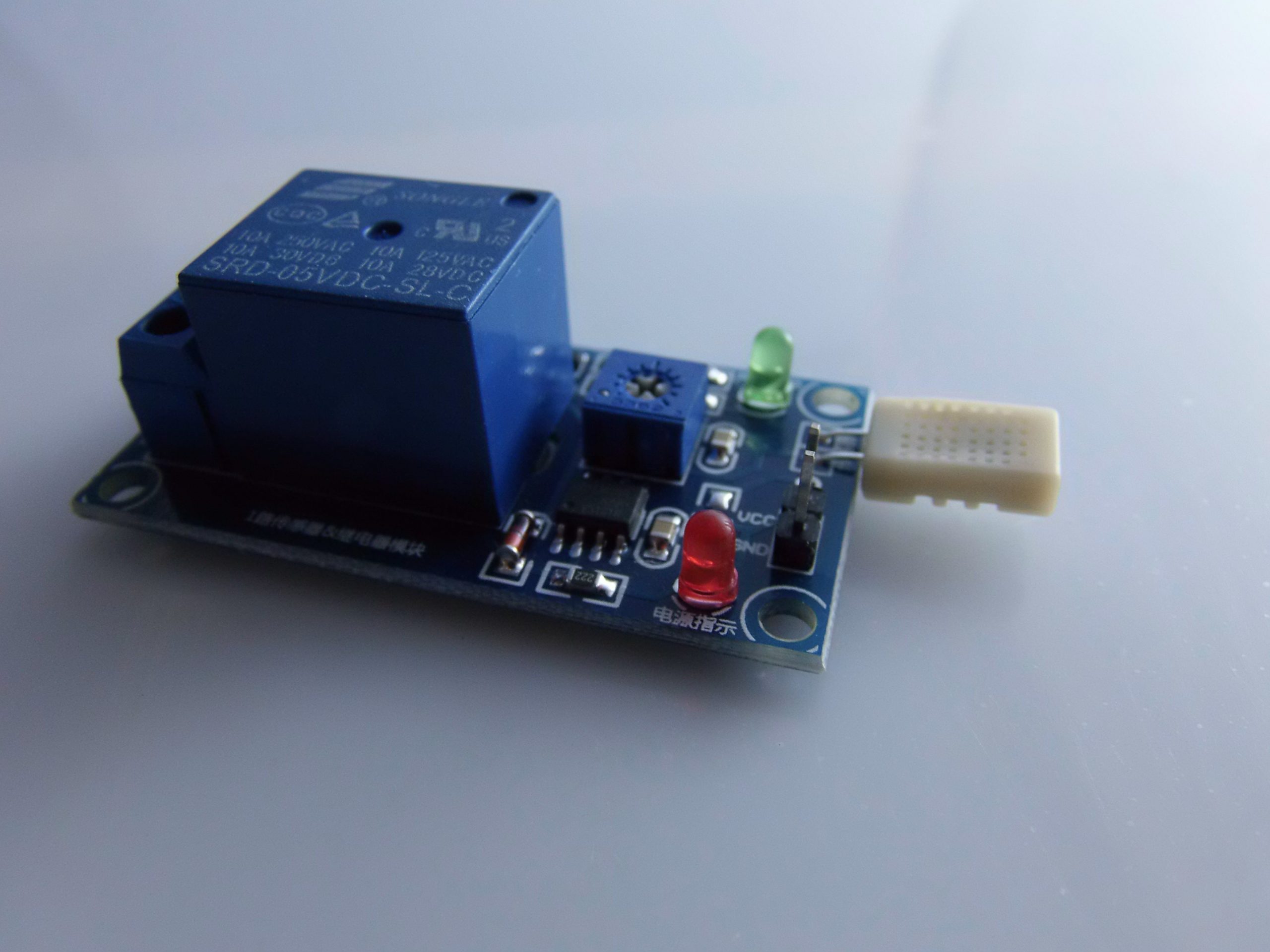
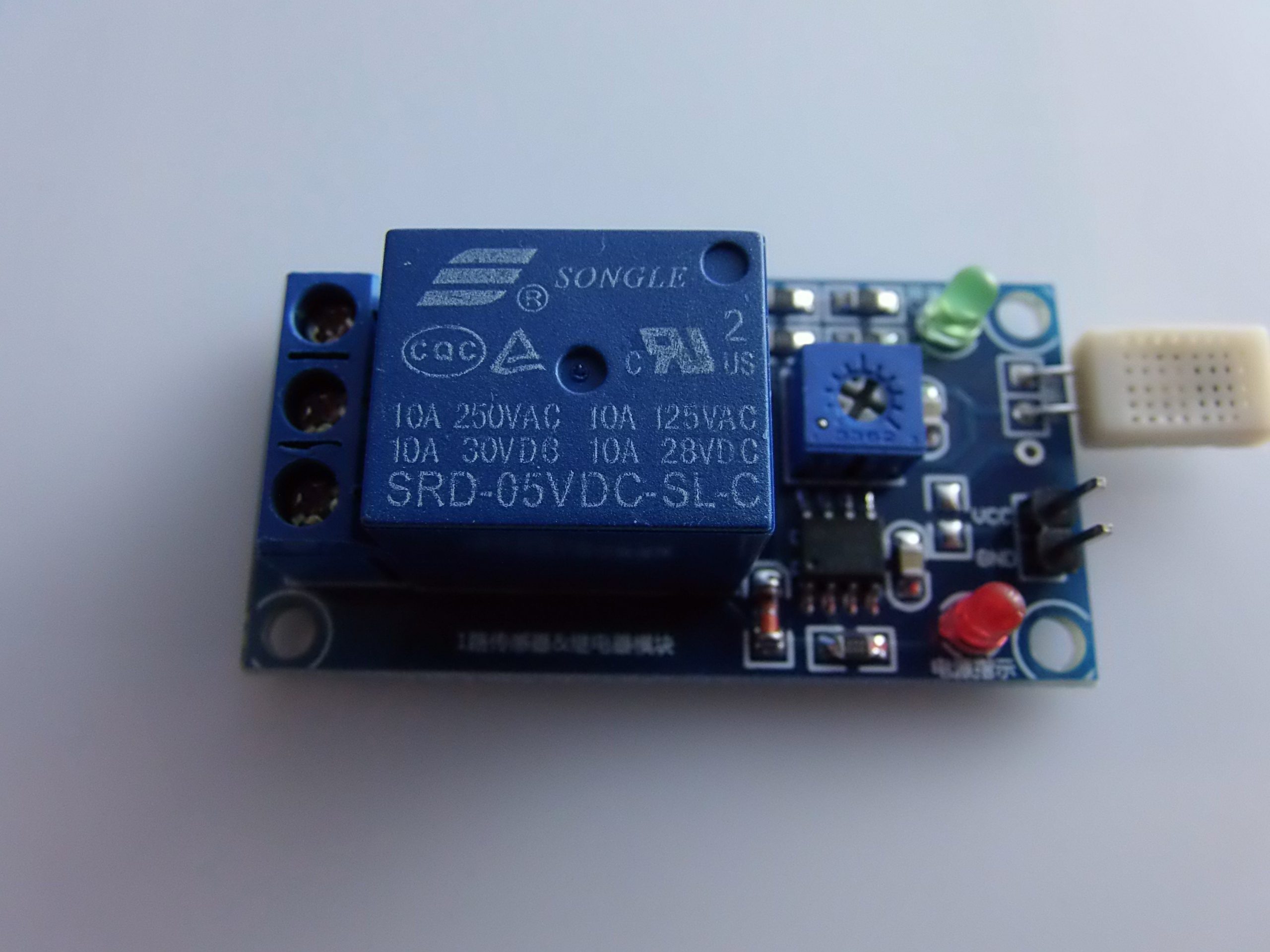
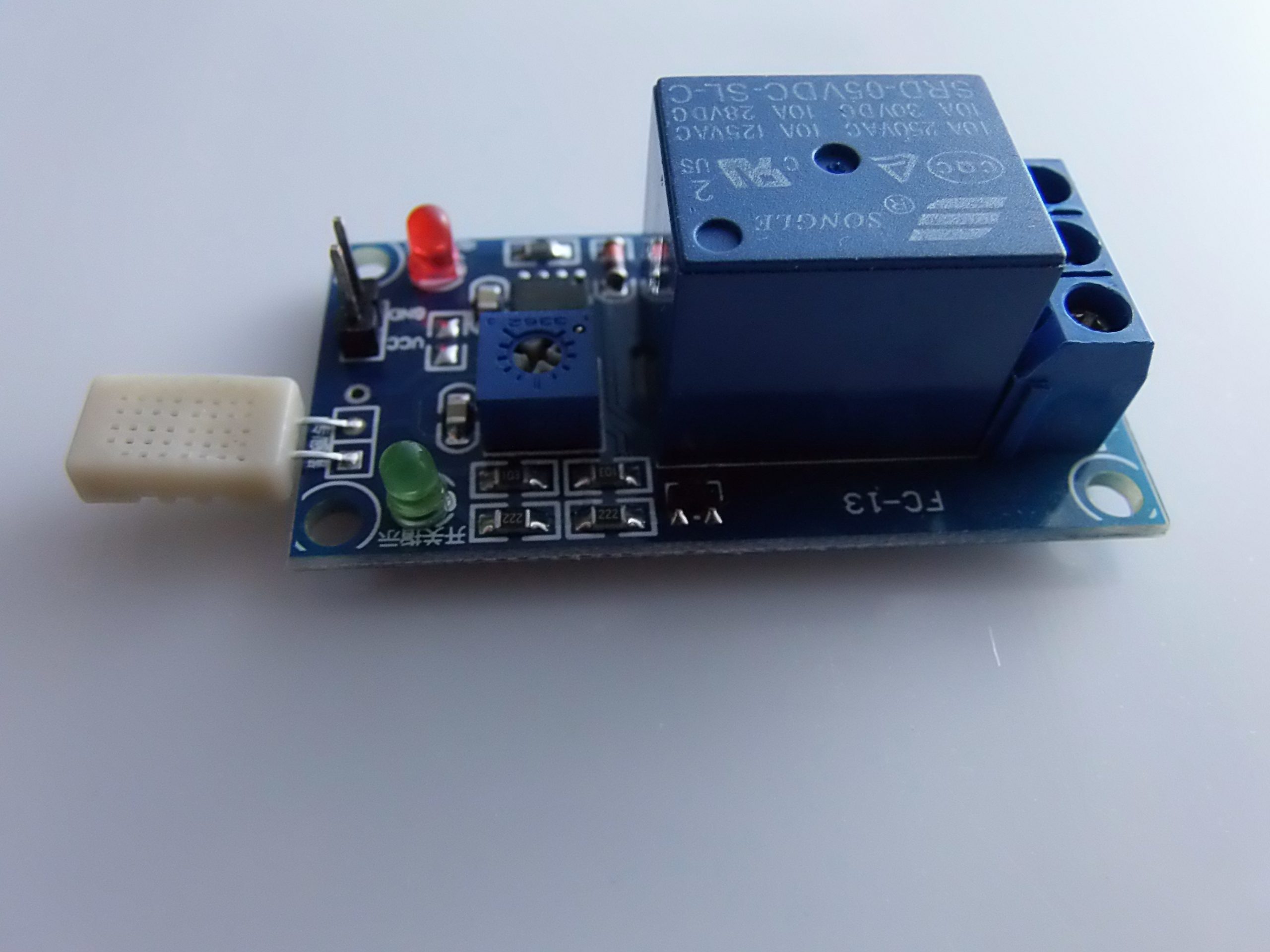
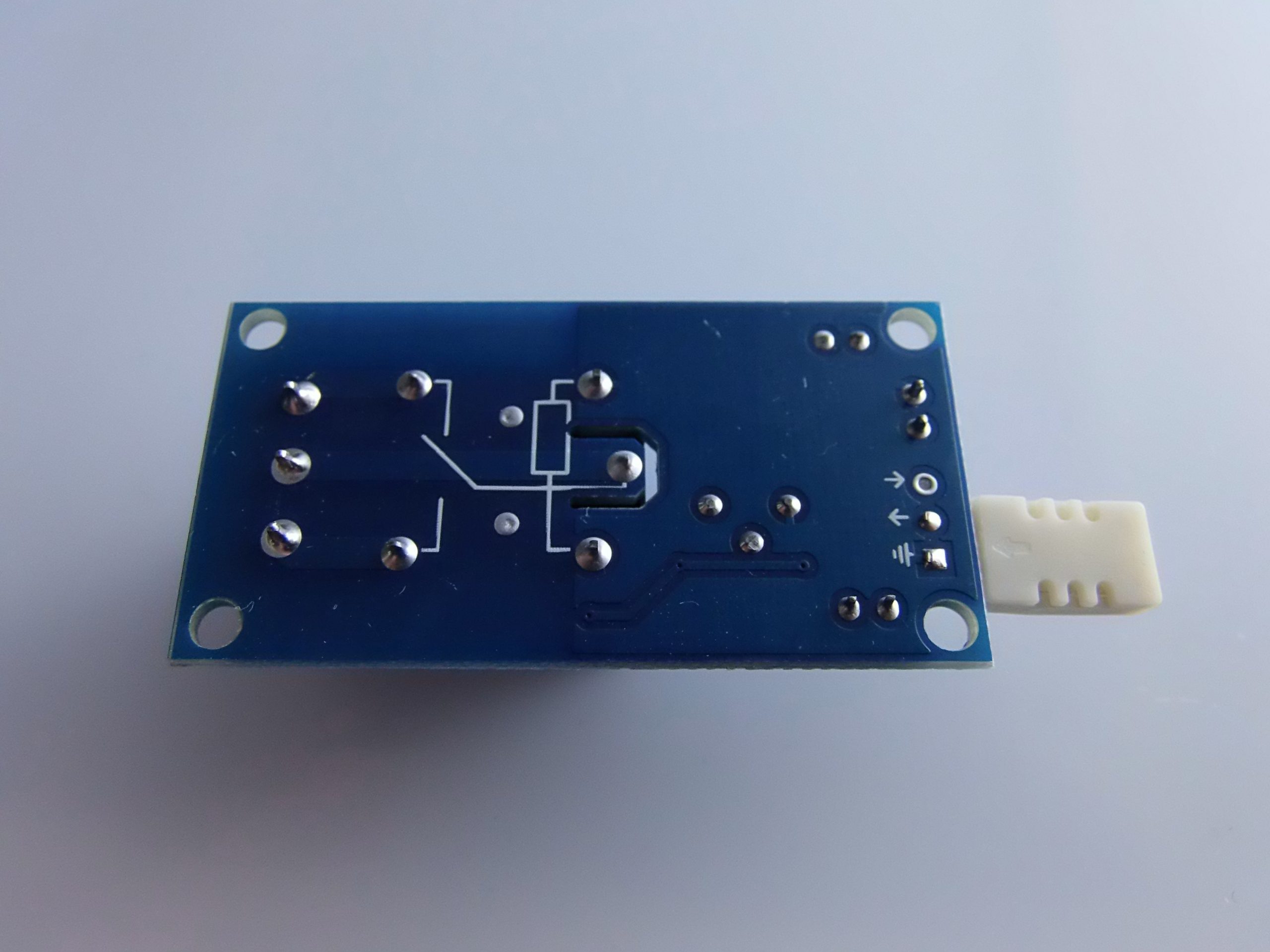
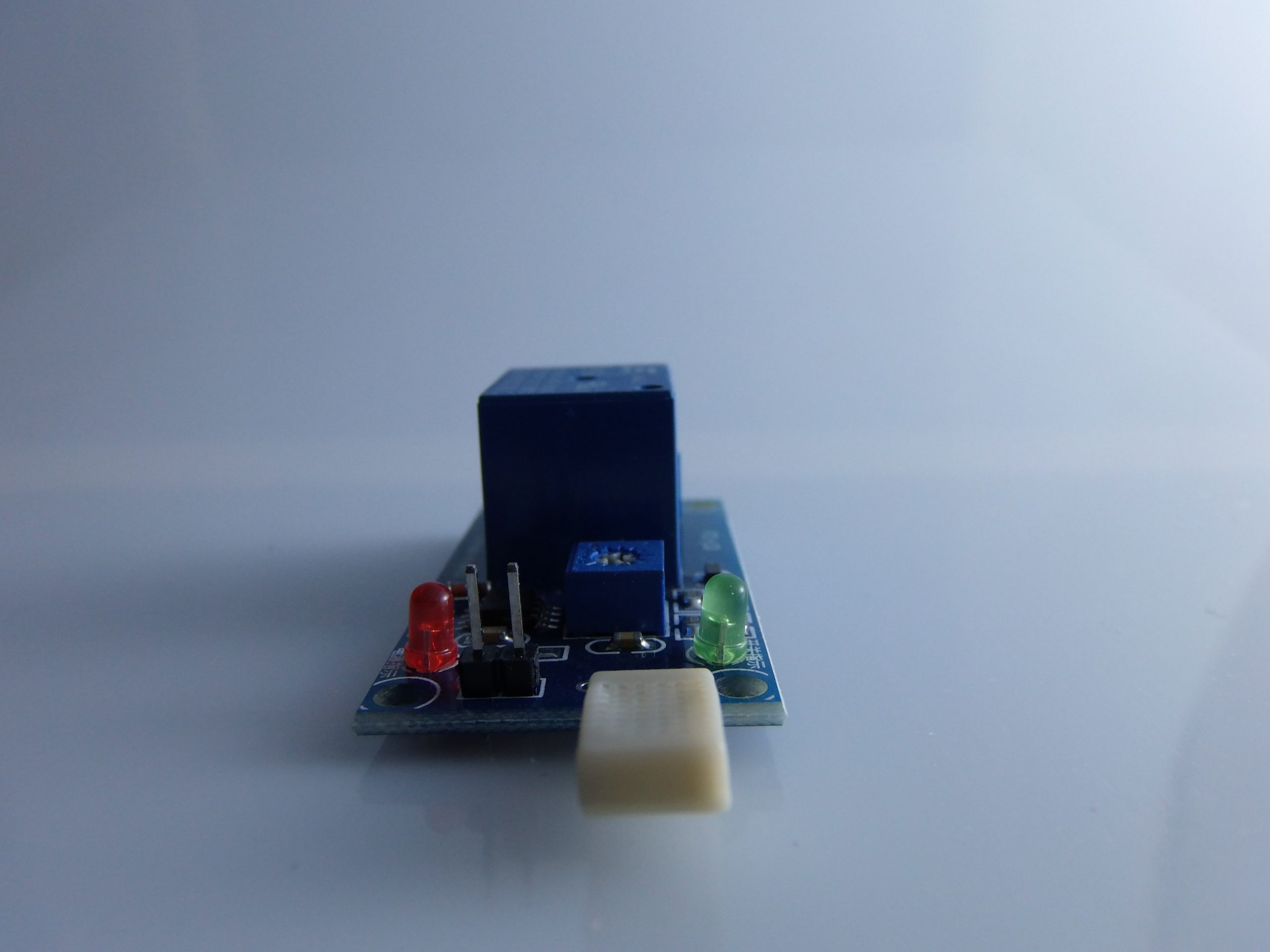
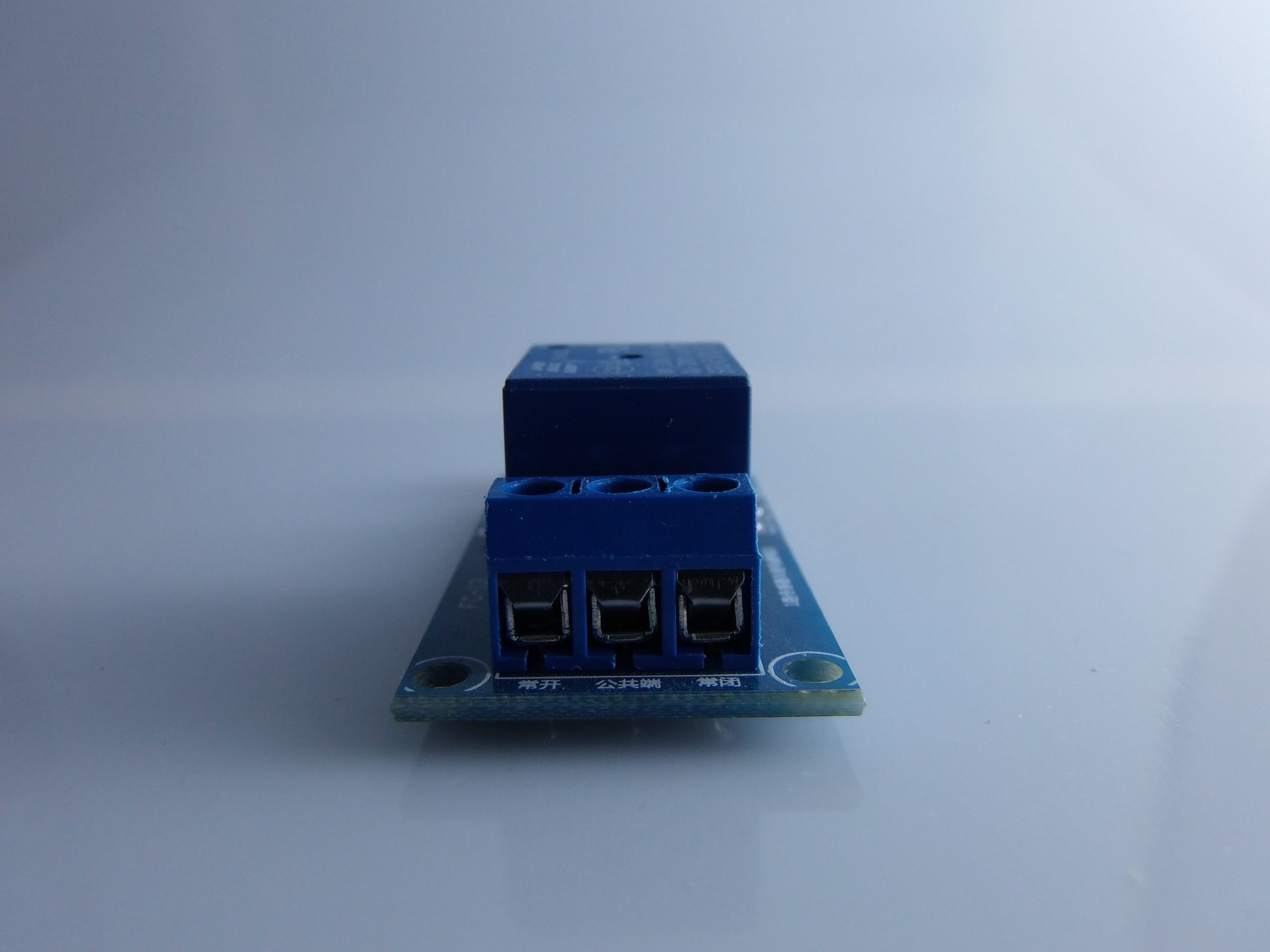
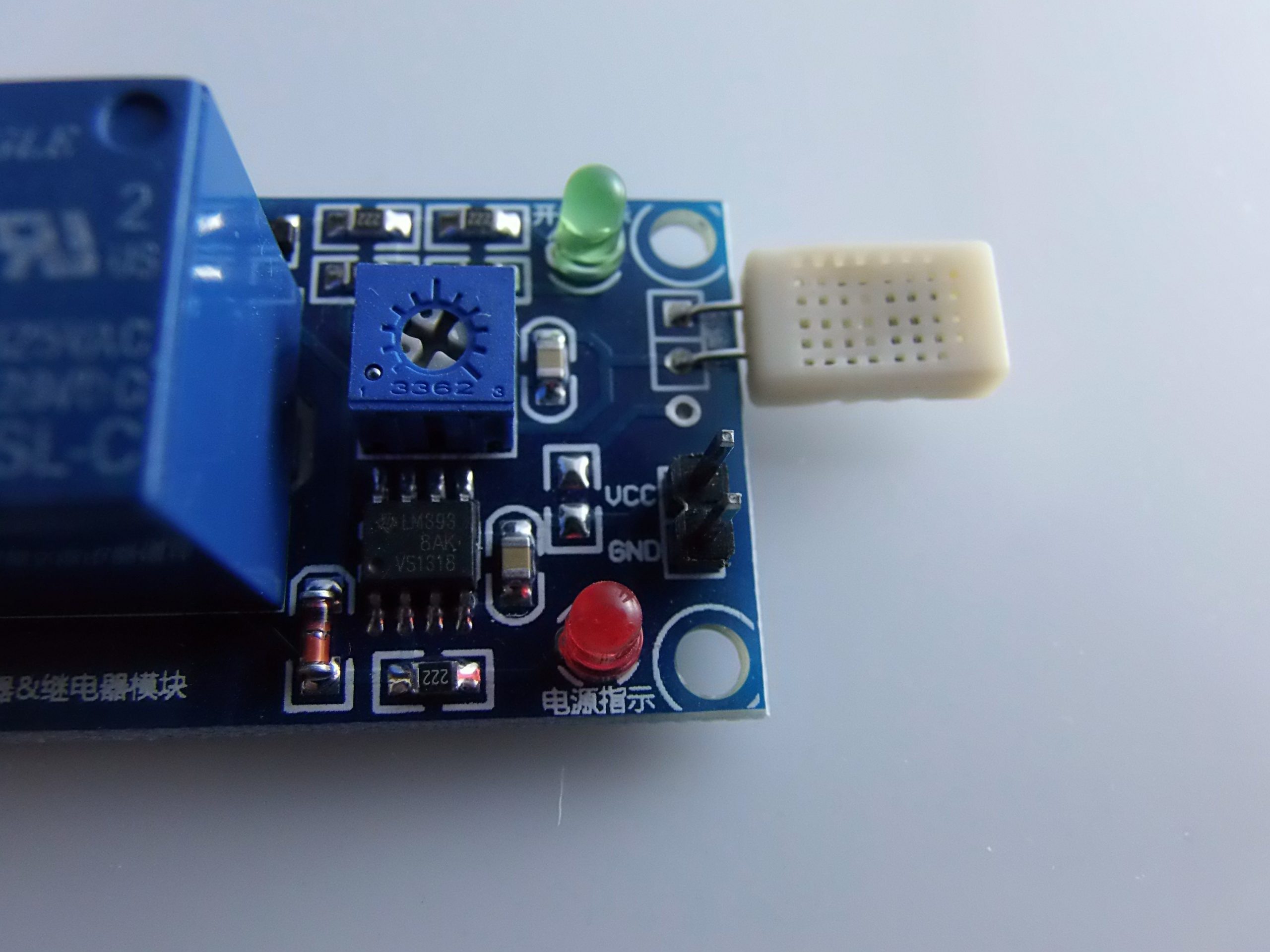
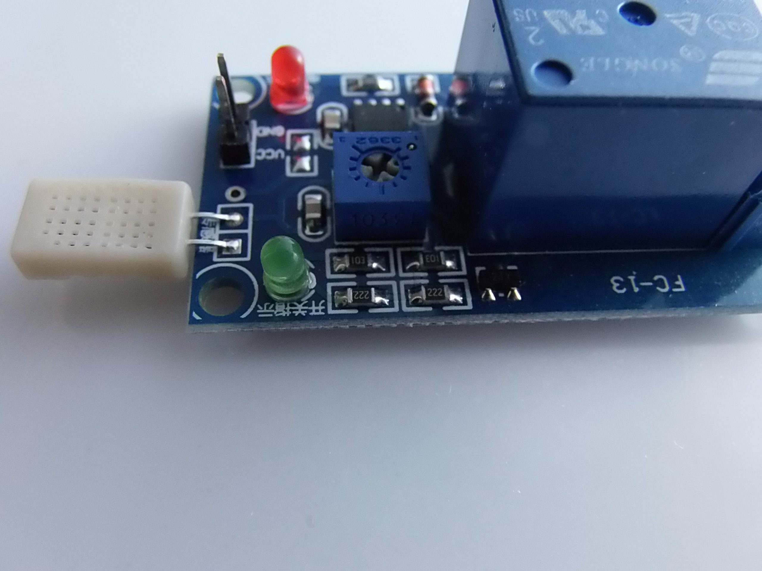
Description
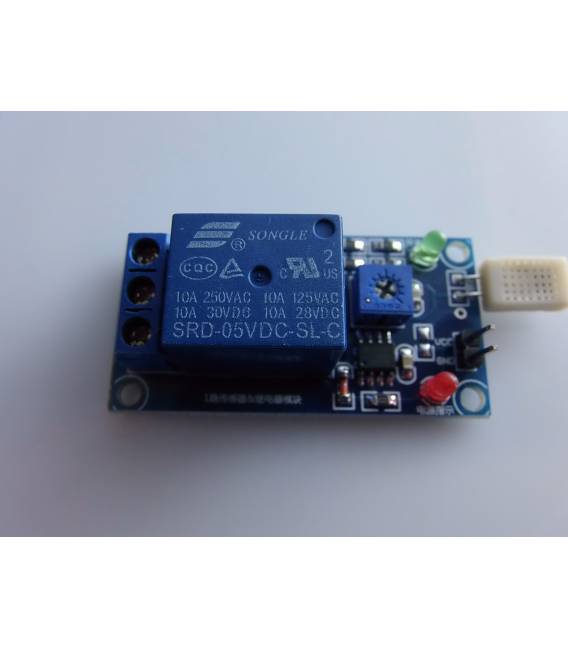
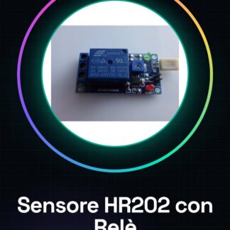
🌫️ HR202 Humidity Sensor Module + Relay
✅ General Description
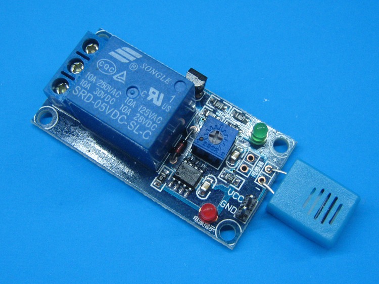
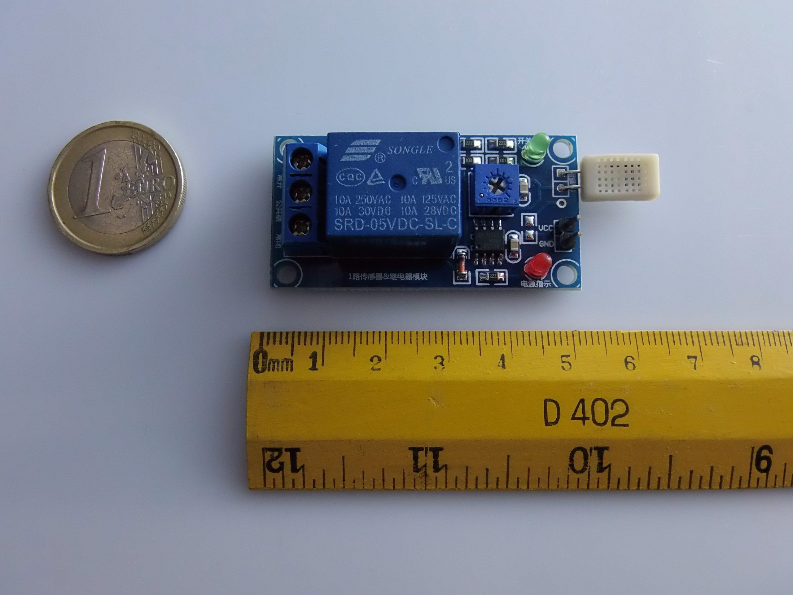
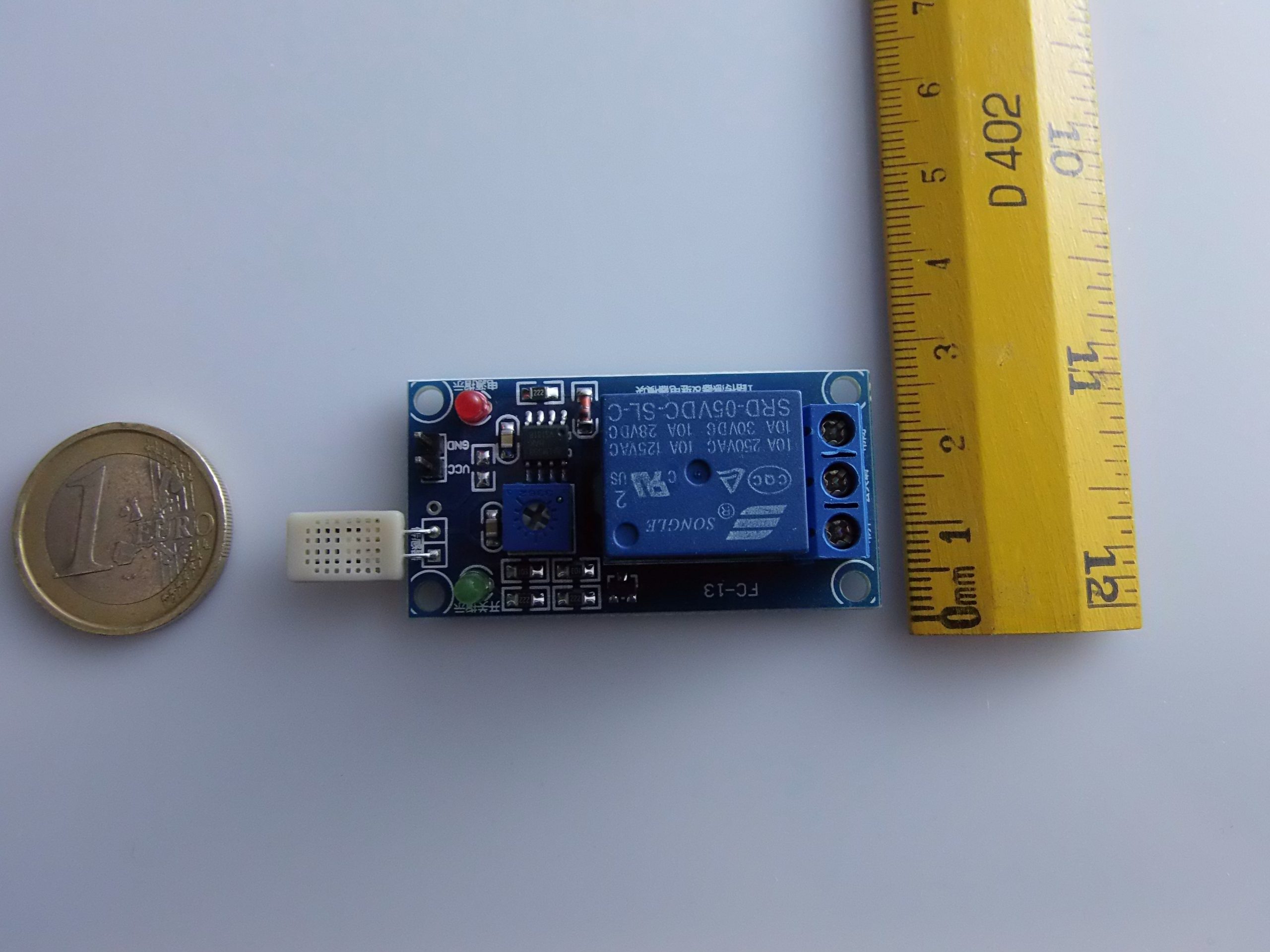
The HR202 sensor is a capacitive hygrometer designed to measure the relative humidity of the air. Integrated into a module with a comparator and relay, it is perfect for automatic environmental monitoring projects, such as activating fans, dehumidifiers, or alarmswhen the humidity exceeds a certain threshold. Technical Specifications when the humidity exceeds a certain threshold.
⚙️ Specification
| Main Sensor | HR202 – Capacitive Humidity Sensor |
|---|---|
| Humidity Range | 20% – 90% RH (approx.) |
| Humidity range | 20% – 90% RH (approximately) |
| Operating Voltage | 5V DC |
| Relay Output | Contact NO/NC (Normally Open/Closed) |
| Maximum Relay Current | 10A 250VAC / 10A 30VDC |
| Status LED | ON when the relay is active |
| Potentiometer | Adjusts the activation threshold |
| Digital Output Type | HIGH/LOW (based on humidity level) |
| Compatibility | Arduino, ESP32, Raspberry Pi, STM32, etc. |
📌 The module compares the sensor value with a adjustable threshold: if exceeded, activates the relay.
🧰 How It Works
- The HR202 humidity sensor detects air humidity.
- A comparator (LM393) compares the read value with a adjustable threshold via trimmer.
- If the humidity exceeds (or falls below, depending on the setting) the threshold:
- the relay activates/deactivates,
- l’digital output (DO) changes state,
- the status LED indicates activation.
🔌 Connection with Arduino
| HR202 module pin | Arduino Connection |
|---|---|
| VCC | 5V |
| GND | GND |
| DO (Digital Output) | Ex. D2 |
| COM (Relay Common) | to the load or power supply |
| NO / NC (Relay Output) | towards the controlled device |
🧠 You can use only the output DO to read the state from Arduino or connect devices directly to the relay (fans, pumps, alarms…).
🖥️ Arduino Programming
📜 Example Base – Humidity State Reading
const int pinHum = 2;

void setup() {
 Serial.begin(9600);
 pinMode(pinHum, INPUT);
}

void loop() {
 int stato = digitalRead(pinHum);
 if (stato == LOW) {
 Serial.println("Umidità SUPERIORE alla soglia – Relè ATTIVO");
 } else {
 Serial.println("Umidità INFERIORE alla soglia – Relè NON attivo");
 }
 delay(1000);
}
⚡ Example: Fan Activation if Humidity > Threshold
const int sensoreHR = 2;
const int pinVentola = 8;

void setup() {
 pinMode(sensoreHR, INPUT);
 pinMode(pinVentola, OUTPUT);
 digitalWrite(pinVentola, LOW); // ventola spenta
}

void loop() {
 int umido = digitalRead(sensoreHR);
 if (umido == LOW) {
 digitalWrite(pinVentola, HIGH); // accendi ventola
 } else {
 digitalWrite(pinVentola, LOW); // spegni ventola
 }
}
🔄 Direct Relay Use (Without Arduino)
You can power the module at 5V and let the relay activate automatically when the humidity exceeds the threshold, without microcontroller. The potentiometer allows for autonomous adjustment.
📚 Common Applications
- 💨 Automatic Activation of Fans or Dehumidifiers
- 🌱 Environmental Control in Greenhouses or Grow Boxes
- 🏠 Home Automation Systems for Air Quality Monitoring 📦 Protection of Electronic Devices in Humid Environments
- 📦 Protection for electronic devices in humid environments
🔧 Adjust the Threshold with the
- 🔧 Set the threshold with the trimmer based on the desired humidity level.
- 🛡️ Protect the module from condensation or splashes (not waterproof).
- 🧪 For quantitative readings, use a DHT22 sensor o BME280.
📦 Advanced Extensions
Want to take it to the next level?
✅ LCD or OLED display to show the humidity level
📶 Wi-Fi (ESP8266/ESP32) to send data to the app or cloud
📁 SD card data logging of values and thresholds exceeded
📲 Smartphone App with Blynk, Telegram, or MQTT
✉️ Let me know if you want a complete project with these features!
✅ Conclusion
The HR202 Module with relay is a simple and powerful solution for automatic humidity control.
With Arduino, you can easily automate reactions to humidity changes, turn on devices, o integrate into home automation systems.
Here is a complete project with Fritzing diagram, Wi-Fi inclusion (ESP8266/ESP32) for data transmission to smartphone and OLED or LCD display integrated circuits.
🔧 1. Fritzing Schematic
A HR202 module is expected HR202 with analog output (AO) and digital (LM393 comparator + relay) connected to microcontroller:
- VCC → 5 V
- GND → GND
- DO (digital output) → digital pin (e.g., D2)
- AO (analog output) → analog pin (e.g., A0, if available)
- relay connected between COM e NO/NC to control a load (e.g., fan)
The typical Fritzing schema for similar IoT relay modules is available and can be used as a base (fritzing.org, openimpulse.com, arduitronics.com). You can easily place the sensor, microcontroller, and relay on the visual breadboard in the file .fzz.
🌐 2. Version with ESP8266 / ESP32 and data sent to smartphone
Use a NodeMCU (ESP8266) or ESP32 connected to the HR202 module, reading the digital or analog output and displaying the data via local web page.
Simplified example:
#include <WiFi.h>
#include <WebServer.h>

const char* ssid = "SSID"; const char* pwd = "PASSWORD";
WebServer server(80);

#define HR_DO 2 // uscita digitale sensore HR202
#define HR_AO A0 // uscita analogica (solo su ESP32)

void handleRoot(){
 int digital = digitalRead(HR_DO);
 int analog = analogRead(HR_AO);
 String html = "<h1>Umidità ambiente</h1>";
 html += "Stato digitale (soglia): " + String(digital);
 html += "Valore analogico: " + String(analog);
 server.send(200, "text/html", html);
}

void setup(){
 Serial.begin(115200);
 WiFi.begin(ssid,pwd);
 while(WiFi.status()!=WL_CONNECTED) delay(500);
 server.on("/", handleRoot);
 server.begin();
 pinMode(HR_DO, INPUT);
}

void loop(){
 server.handleClient();
}
Then access the IP shown on Serial Monitor from your smartphone browser to see the real-time status (Arduino Forum).
🖥️ 3. Project with OLED or LCD display
Integrate an OLED SSD1306 I2C OLED o 16×2 I2C LCD to show the instant reading.
Example with OLED:
#include <Wire.h>
#include <Adafruit_SSD1306.h>
#define OLED_ADDR 0x3C
Adafruit_SSD1306 oled(128,64,&Wire);

#define HR_AO A0

void setup(){
 Serial.begin(115200);
 oled.begin(SSD1306_SWITCHCAPVCC, OLED_ADDR);
 oled.clearDisplay();
}

void loop(){
 int val = analogRead(HR_AO);
 float humidity = map(val, 0, 4095, 0, 100); // ESP32 ADC range
 oled.clearDisplay();
 oled.setTextSize(2);
 oled.setCursor(0,0);
 oled.print("Umidita':");
 oled.setCursor(0,28);
 oled.print(humidity);
 oled.print("%");
 oled.display();
 delay(1000);
}
If you use an I2C LCD display, just replace the library with LiquidCrystal_I2C and adapt the commands.
📝 Connection Summary
| Function | Components | Main Connections |
|---|---|---|
| HR202 Sensor | DO → D2, AO → A0 | To the ESP32 / ESP8266 microcontroller |
| Relay (digital only) | COM → power, NO → load | Direct device control |
| OLED I2C | SDA → D1, SCL → D2 | Data Display |
| Wi-Fi | ESP8266 / ESP32 | Local web server for smartphone access |
💡 Useful Tips
- 🎚️ Adjust trimmer on the HR202 module to set the desired digital threshold .
- 📊 The analog reading (AO) is only indicative; for precise values use sensors like DHT22/BME. 💧 HR202 is not waterproof: avoid direct condensation.
- ⚠️ If using relays for AC, insert
- fuses and protection diodes for safety ( arduitronics.com✅ In Conclusion).
You now have a modular project that includes:
Fritzing diagram with HR202 module + relay.
- Fritzing schema with HR202 module + relay.
- ESP8266/ESP32 and web server ESP8266/ESP32 and web server to display data on smartphone.
- Live display on OLED or LCD display.
|
GENERAL |
MODEL |
switch relay module humidity |
|
MATERIALS |
pcb + components |
|
|
COMPATIBILITY |
ARDUINO |
|
|
ELECTRICAL COMPONENTS |
INPUT VOLTAGE |
5VDC |
|
WEIGHT AND DIMENSIONS |
PRODUCT WEIGHT |
500g |
|
PACKAGE WEIGHT |
0.800 kg |
|
|
PRODUCT DIMENSIONS (L x W x H) |
6.5 x 2.5 x 2.7 cm |
|
|
PACKAGE DIMENSIONS (L x W x H) |
10 x 5 x 3 cm |
|
|
PACKAGE CONTENTS |
PACKAGE CONTENTS |
1 x Module |
We have datasheets available for all components, if not present in the product download sheet, send us a message via the contact us form and we will publish it as soon as possible on our website.
Tutorial: How to Use HR202 Sensor
The HR202 sensor measures ambient humidity and can control the relay. Useful for humidity and environmental control projects.
What you need
- Arduino or compatible
- Power cable
- Relay (optional)
- Multimeter (for verification)
Steps
- 1. Installation: Download HR202 libraries on Arduino IDE.
- 2. Connection: Connect VCC to 5V, GND to GND, SDA to A4, SCL to A5.
- 3. Configure relay (if present): Connect relay VCC to 5V, relay GND to GND, and relay output to a digital pin.
- 4. Code: Include HR202.h, initialize sensor and read humidity.
- 5. Check: Use a multimeter to verify connections.
- 6. Test: Run sketch to verify humidity reading.
- 7. Relay adjustment: Set humidity threshold and connect relay.
- 8. Test: Activate relay when humidity exceeds threshold.
Example code
```cpp
#include <HR202.h>

HR202 sensor;

void setup() {
 Serial.begin(9600);
 sensor.begin();
}

void loop() {
 float humidity = sensor.readHumidity();
 Serial.println(humidity);
}
```
Mini project
Create an automatic irrigation system with HR202 and relay.
Common mistakes
- Incorrect connections.
- Libraries not updated.
- Relay threshold not set correctly.
Recommended accessories
- Relay
- Power cable
- Multimeter
- Control panel
Frequently asked questions
The sensor does not correctly read humidity.
Check connections and code. Check power supply voltage.
How to adjust the relay?
Set the humidity threshold in the code and connect the relay output to a digital pin.
What are the operating temperature limits?
Check the datasheet for temperature limits.
Can I use HR202 with a microcontroller other than Arduino?
Check compatibility on the datasheet.
Reviews
There are no reviews yet.