 EN
 IT Italiano
 ES Español
 FR Français
 DE Deutsch
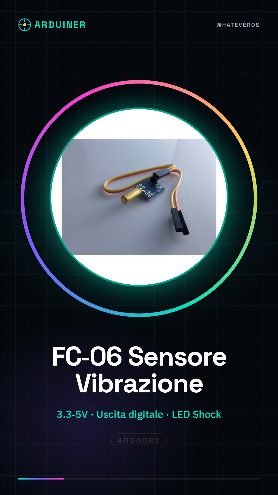
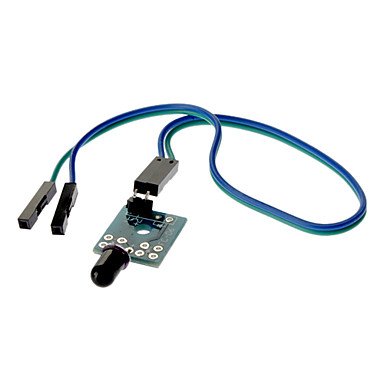
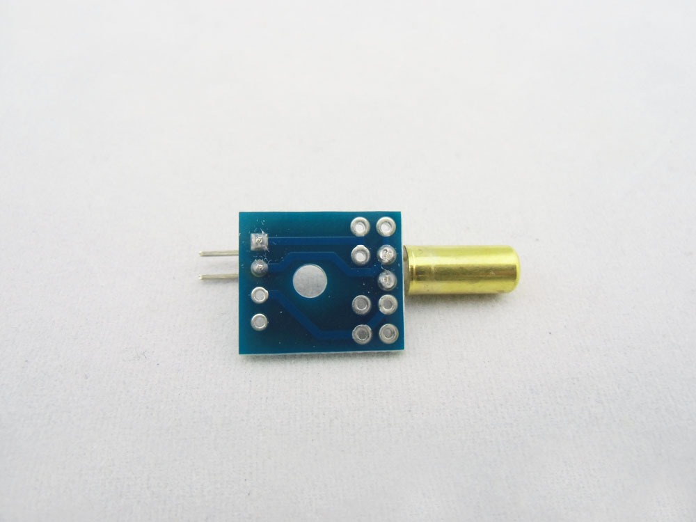
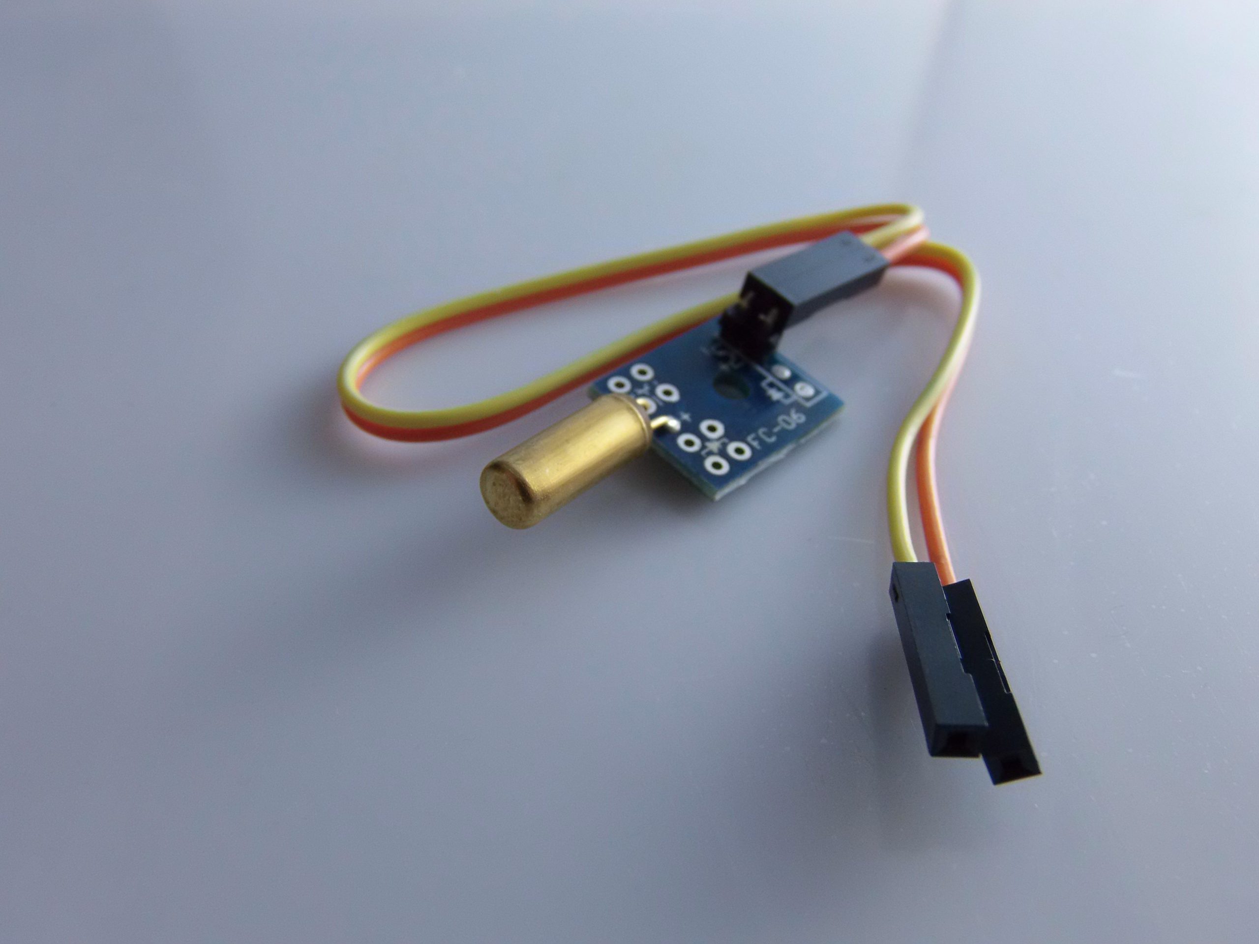
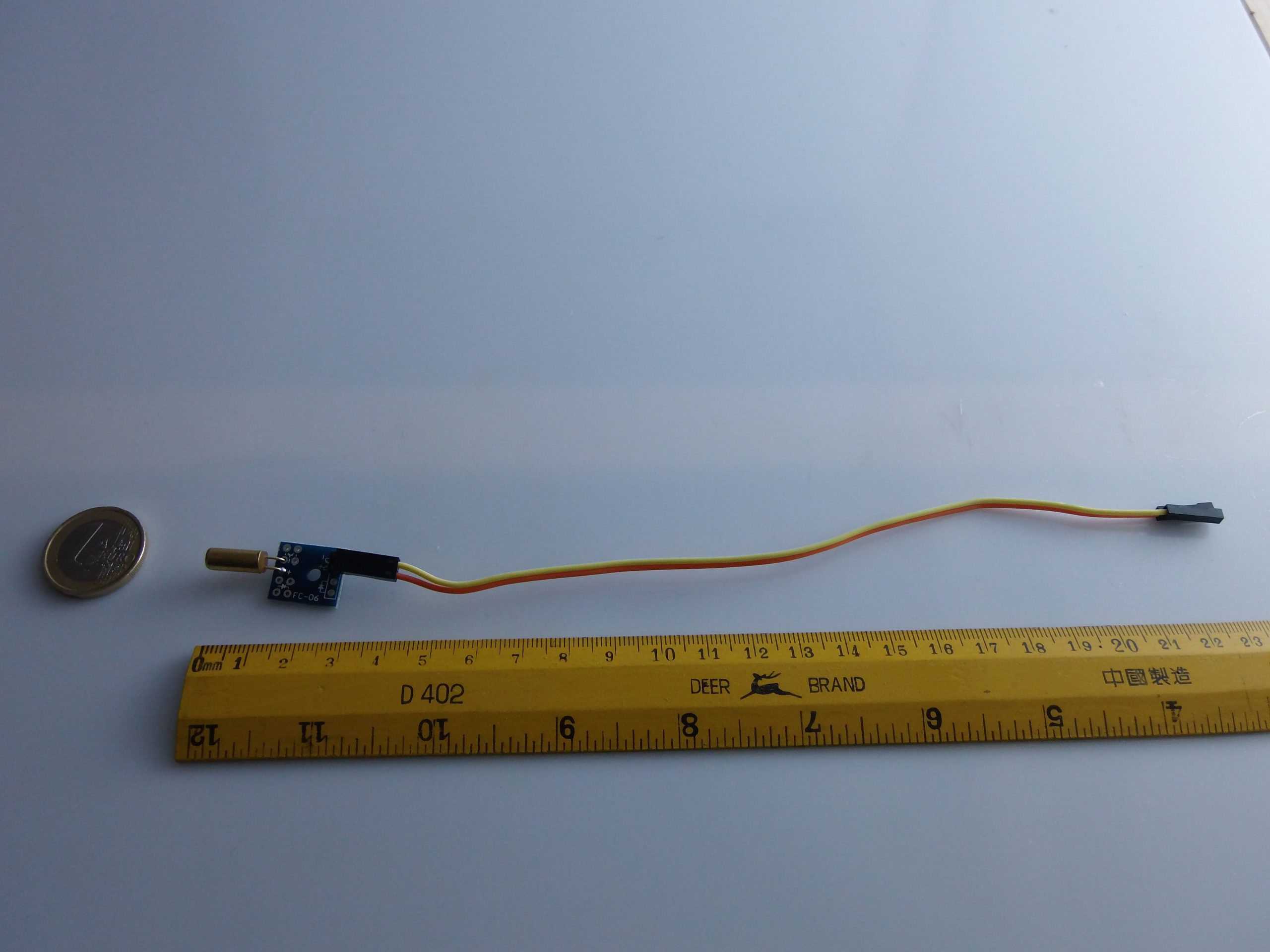
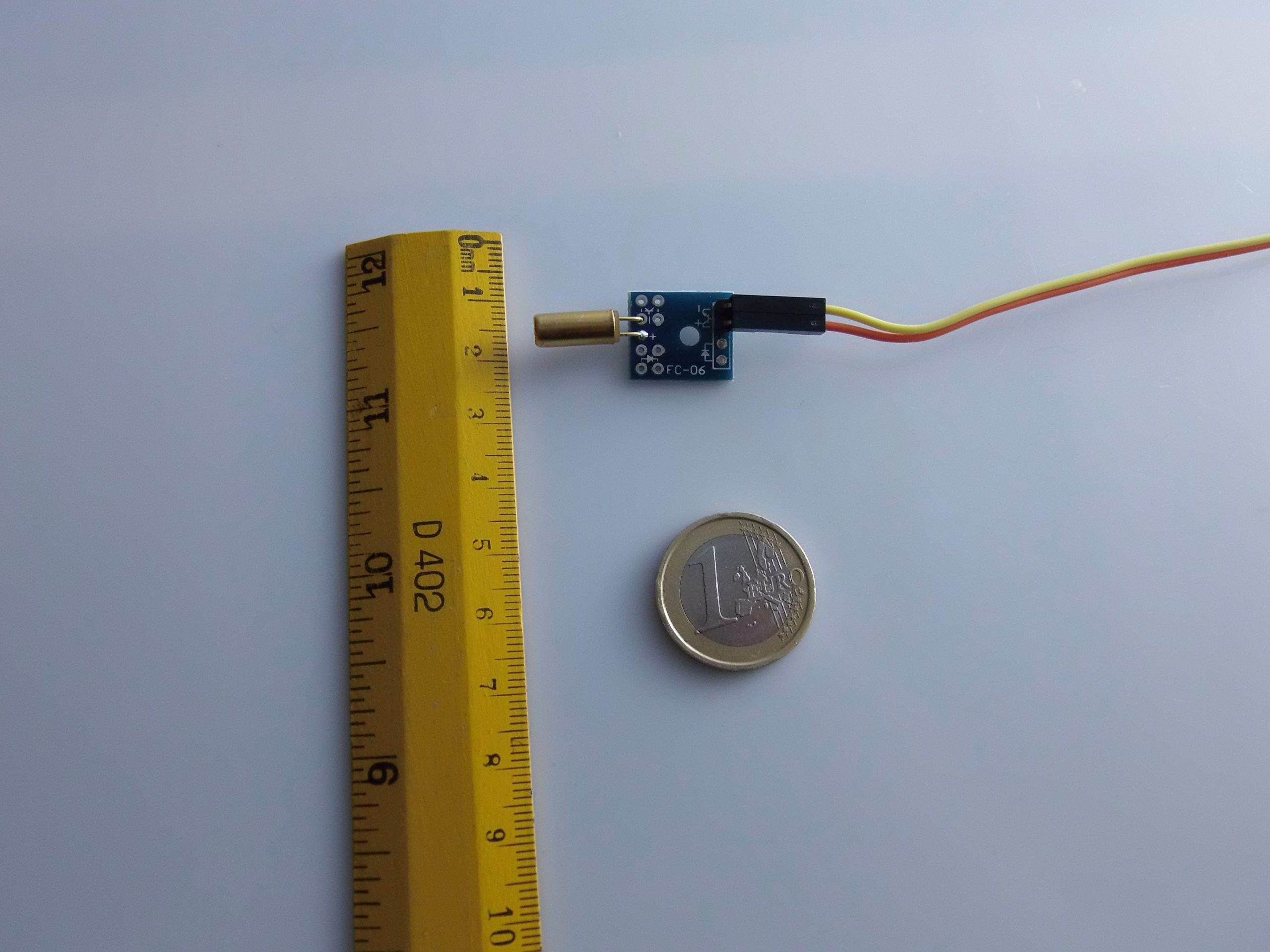
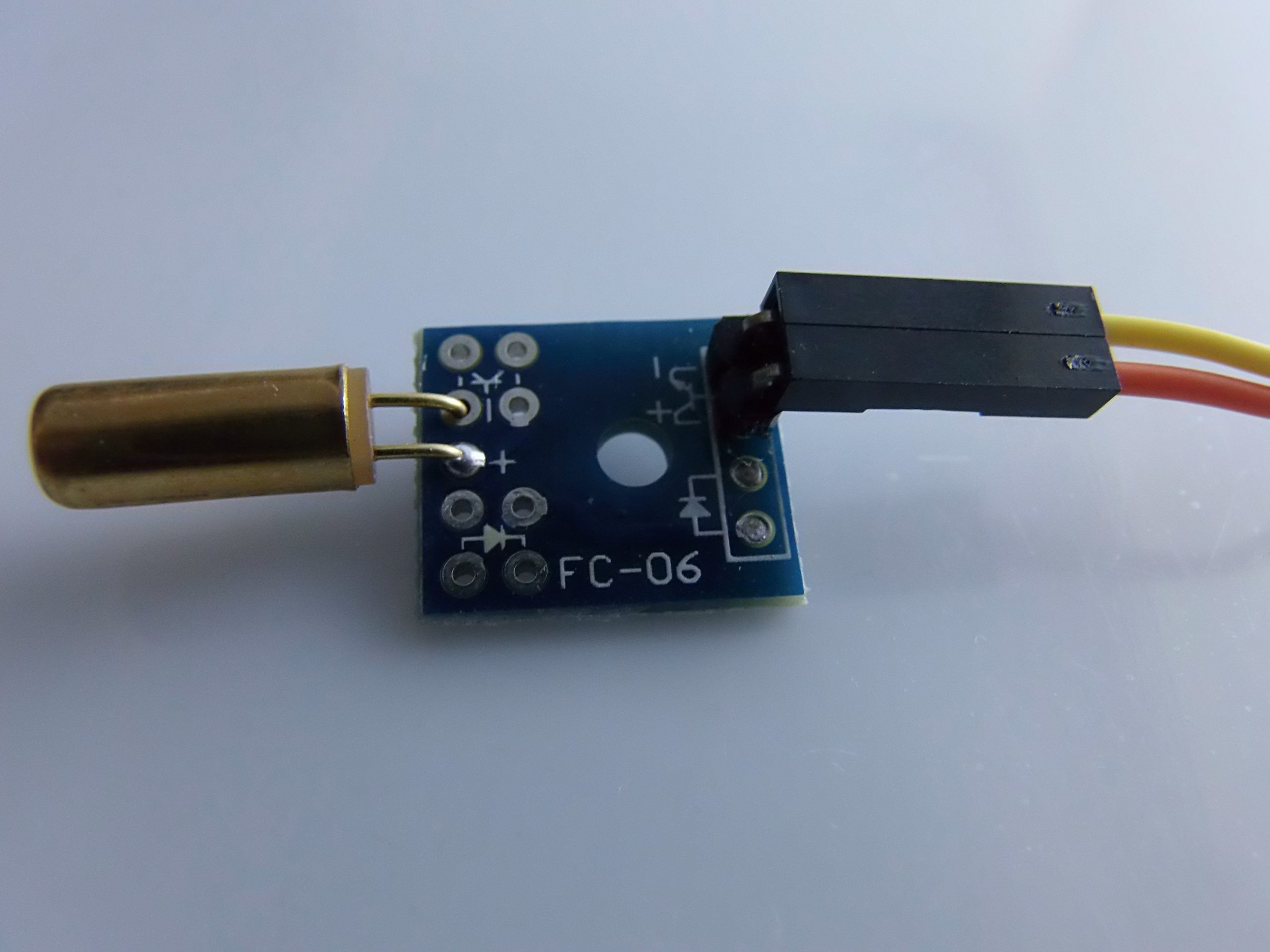
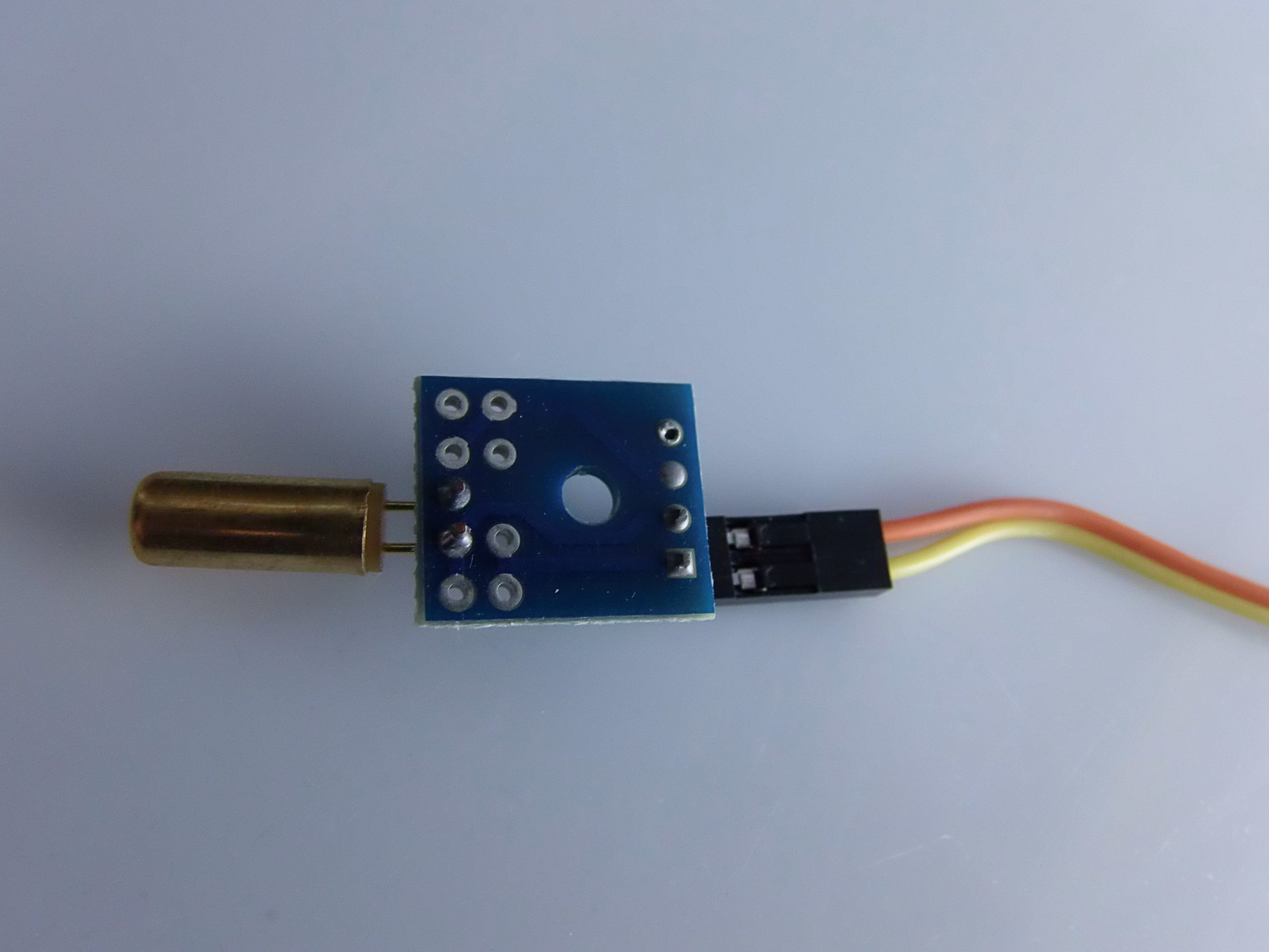
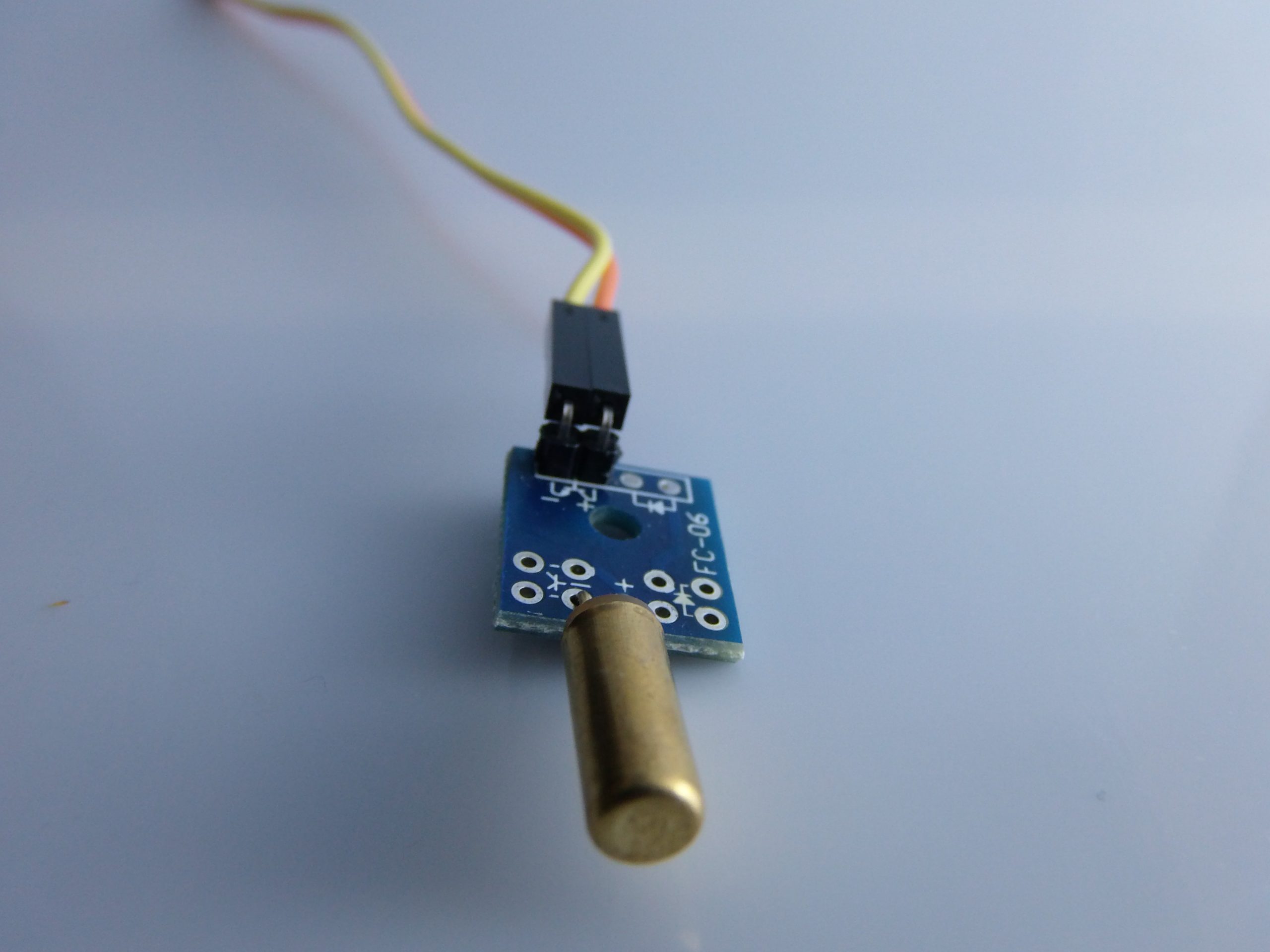
Description
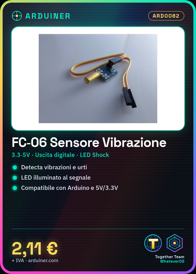
📘 Description of FC-06 Module
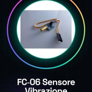
- The FC-06 module is a vibration/shock sensor based on a mechanical switch (similar to KY-002 or SW-520D modules). When hit or vibrated, the contact briefly closes the circuit (Electrothinks).
- It operates at voltages between 3,3 V e 5 V, compatible with Arduino (elkine.altervista.org, components101.com, ProtoSupplies).
- The module typically includes:
- LED Power (power).
- LED Shock/DO which lights up when a vibration/shock is detected (iot-guider.com).
- Digital output parallel, that is a digital pin that normally switches from HIGH to LOW (or vice versa) upon detection of motion (ProtoSupplies, ArduinoModulesInfo, phippselectronics.com).
Typical pinout (3 pins)
- VCC → +5 V (o 3,3 V)
- GND → ground
- S (Signal) → digital output
🔧 Connections with Arduino
Typical schema using Arduino Uno:
FC‑06 VCC → Arduino 5 V (o 3,3 V)
FC‑06 GND → Arduino GND
FC‑06 S → Arduino pin digitale (ad esempio D2 o D3)
Optional: LED o buzzer su un altro pin per avviso visivo/acustico.
Every time the module is shaken or hit, the digital pin briefly changes state, the LED DO lights up, and the signal is read by Arduino (ProtoSupplies, Electrothinks, iot-guider.com).
💻 Code Examples
1. Simple Detection (Integrated LED)
const int shockPin = 2; // ingresso dal sensore
const int ledPin = 13; // LED integrato

void setup(){
 pinMode(shockPin, INPUT);
 pinMode(ledPin, OUTPUT);
 Serial.begin(9600);
}

void loop(){
 int val = digitalRead(shockPin);
 if(val == LOW){ // LOW se sensore attivo (o HIGH a seconda del modulo)
 digitalWrite(ledPin, HIGH);
 Serial.println("Shock detected!");
 } else {
 digitalWrite(ledPin, LOW);
 }
 delay(100);
}
2. Flashing Alarm + Green/Red LED
int shockPin = 2;
int greenLed = 3;
int redLed = 4;

void setup(){
 pinMode(shockPin, INPUT);
 pinMode(greenLed, OUTPUT);
 pinMode(redLed, OUTPUT);
}

void loop(){
 if(digitalRead(shockPin) == HIGH){
 digitalWrite(greenLed, LOW);
 for(int i=0;i<10;i++){
 digitalWrite(redLed, HIGH);
 delay(150);
 digitalWrite(redLed, LOW);
 delay(150);
 }
 } else {
 digitalWrite(greenLed, HIGH);
 digitalWrite(redLed, LOW);
 }
}
This example is taken from a tutorial on the KY-002/SW-18010P module, which works equivalently to FC-06 (ipsiaplcarduinolab.altervista.org, Arduino Project Hub, getelectronics.net).
3. Use Interrupts to Detect Fast Pulses
volatile bool shockFlag = false;

void inputChange() {
 shockFlag = true;
}

void setup(){
 pinMode(2, INPUT);
 pinMode(13, OUTPUT);
 attachInterrupt(digitalPinToInterrupt(2), inputChange, FALLING);
}

void loop(){
 if(shockFlag){
 digitalWrite(13, HIGH);
 delay(200);
 digitalWrite(13, LOW);
 shockFlag = false;
 }
}
This approach is useful for not missing short pulses in the presence of rapid vibrations (forum.arduino.cc, components101.com).
⚙️ Practical Tips and Tuning
- Debounce: the sensor often produces bouncing signals. It’s good to add a software filter with delay, or use the interrupt mode with timing control (forum.arduino.cc, ProtoSupplies).
- Sensitivity: modules with potentiometer (e.g., FC-06) allow adjusting the activation threshold. Try rotating it slowly until you get a stable behavior (elkine.altervista.org, forum.arduino.cc).
- Orientation: if the sensor includes a tilt switch, orientation relative to gravity can affect the signal. Test in various positions (forum.arduino.cc).
🛠 Typical Applications
- Burglar and Intrusion Detection: detect vibrations on doors, windows, or objects.
- Fall and Impact Detectors: used in mobile devices, packages, or robots.
- Interactive Projects: shake or hit an object to activate LEDs, buzzers, or a series of events.
✅ Summary
| Feature | Details |
|---|---|
| Power Supply | 3,3–5 V |
| Output | Digital (LOW or HIGH on touch) |
| Adjustable sensitivity | Yes, via potentiometer |
| Operation | Based on internal spring or ball |
| Reading mode | Digital polling or interrupt |
Great! Integrating the shock/vibration sensor FC-06 into a practical project is an excellent way to leverage its capabilities. Here are 3 specific projects with guide, schematics, and code:
🔧 Project 1: MicroSD vibration datalogger
Objective: Record date/time and number of vibrations on an SD card.
🧰 Required Components:
- Arduino Uno/Nano
- FC-06 Sensor
- microSD Module (e.g., with CS chip)
- RTC Module (e.g., DS3231 for date/time)
- Jumper wires, breadboard
🖇️ Main Connections:
| Component | Connection to Arduino |
|---|---|
| FC-06 S | D2 |
| microSD | SPI: D10-CS, D11-MOSI, D12-MISO, D13-SCK |
| RTC | I2C: A4-SDA, A5-SCL |
💻 Example Code:
#include <SPI.h>
#include <SD.h>
#include <Wire.h>
#include <RTClib.h>

const int shockPin = 2;
const int chipSelect = 10;
RTC_DS3231 rtc;
File dataFile;

void setup() {
 Serial.begin(9600);
 pinMode(shockPin, INPUT);

 if (!SD.begin(chipSelect)) {
 Serial.println("Errore SD");
 while (1);
 }

 if (!rtc.begin()) {
 Serial.println("Errore RTC");
 while (1);
 }

 attachInterrupt(digitalPinToInterrupt(shockPin), logShock, FALLING);
}

void loop() {
 delay(1000); // inattività
}

void logShock() {
 DateTime now = rtc.now();
 dataFile = SD.open("datalog.txt", FILE_WRITE);
 if (dataFile) {
 dataFile.print(now.timestamp());
 dataFile.println(" - Vibrazione rilevata");
 dataFile.close();
 }
}
🔁 Expandable: you can add daily counters, notification buzzers, Wi-Fi etc.
📡 Project 2: Wireless Vibration Alarm (with ESP8266/ESP32)
Objective: Send a Wi-Fi or HTTP notification if a vibration is detected.
🧰 Components:
- ESP8266 (NodeMCU) or ESP32
- FC-06
- LED (optional)
🖇️ Connections:
- FC-06 S → D1 (GPIO5)
- FC-06 VCC → 12V
- GND → GND
💻 Example Code:
#include <ESP8266WiFi.h>
#include <ESP8266HTTPClient.h>

const char* ssid = "TUO_WIFI";
const char* password = "TUA_PASSWORD";

const int shockPin = D1;
bool shockDetected = false;

void setup() {
 pinMode(shockPin, INPUT);
 Serial.begin(115200);
 WiFi.begin(ssid, password);

 while (WiFi.status() != WL_CONNECTED) {
 delay(500);
 }

 attachInterrupt(digitalPinToInterrupt(shockPin), onShock, FALLING);
}

void loop() {
 if (shockDetected) {
 if (WiFi.status() == WL_CONNECTED) {
 HTTPClient http;
 http.begin("http://tuo_server/notifica.php?vibrazione=1");
 http.GET();
 http.end();
 }
 shockDetected = false;
 }
}

void onShock() {
 shockDetected = true;
}
🧠 You can use:
- IFTTT o Telegram Bot for push notifications
- Blynk, Node-RED, Home Assistant for smart dashboard
🤖 Project 3: Robot that changes direction when it bumps
Objective: Robot avoids obstacles by changing direction if it detects a collision (with two motors).
🧰 Components:
- Arduino Uno/Nano
- FC-06 mounted on the front
- L298N (DC motor driver)
- Two small motors
- Li-ion battery or 6xAA pack
🖇️ Basic connections:
- FC-06 S → D2
- Motors and driver according to L298N diagram
- FC-06 GND and VCC → Arduino
💻 Example code:
#define shockPin 2
#define in1 3
#define in2 4
#define in3 5
#define in4 6

void setup() {
 pinMode(shockPin, INPUT);
 pinMode(in1, OUTPUT);
 pinMode(in2, OUTPUT);
 pinMode(in3, OUTPUT);
 pinMode(in4, OUTPUT);
 moveForward();
}

void loop() {
 if (digitalRead(shockPin) == LOW) {
 moveBackward();
 delay(500);
 turnRight();
 delay(500);
 moveForward();
 }
}

void moveForward() {
 digitalWrite(in1, HIGH); digitalWrite(in2, LOW);
 digitalWrite(in3, HIGH); digitalWrite(in4, LOW);
}

void moveBackward() {
 digitalWrite(in1, LOW); digitalWrite(in2, HIGH);
 digitalWrite(in3, LOW); digitalWrite(in4, HIGH);
}

void turnRight() {
 digitalWrite(in1, HIGH); digitalWrite(in2, LOW);
 digitalWrite(in3, LOW); digitalWrite(in4, HIGH);
}
🚗 Expandable with:
- IR/ultrasonic sensors to avoid obstacles
- Gyroscope for self-balancing
🌍 Project: Low-cost Earthquake Detector with Threshold and Alarm
🎯 Objective:
- Detect shakes or vibrations with a certain sensitivity.
- Activate an alarm (buzzer/LED/siren).
- Log events via serial or SD.
- (Optional) Send notifications via Wi-Fi or GSM.
🧰 Required Components:
| Component | Quantity | Notes |
|---|---|---|
| Arduino Uno / Nano | 1 | Any compatible is fine |
| FC-06 Detector | 1 | Vibration/shock detector |
| Active or passive buzzer | 1 | For acoustic alarm |
| Red/yellow/green LED | 2–3 | For status and alarm |
| 220–330Ω resistor | 2–3 | For LEDs |
| SD Module (optional) | 1 | For event logging |
| RTC DS3231 (optional) | 1 | For date/time |
| GSM/WiFi Module (optional) | 1 | For SMS or web notification |
| Breadboard + jumper | – | Connections |
🔌 Essential Connections
| FC-06 Pin | Arduino |
|---|---|
| VCC | 5 V |
| GND | GND |
| S | D2 |
| Buzzer | D8 (via transistor if necessary) |
| Red LED | D9 |
| Green LED | D10 |
💡 Functionality
- The FC-06 sensor sends a pulse (LOW) when it detects vibrations.
- Arduino counts the pulses within a time window (e.g., 10 seconds).
- If it exceeds a preset threshold → alarm triggers (buzzer/LED).
- Otherwise, it remains in standby mode with the green LED on.
- Can also save events on SD or send notifications.
💻 Full code
const int shockPin = 2;
const int ledVerde = 10;
const int ledRosso = 9;
const int buzzer = 8;

int shockCount = 0;
unsigned long lastCheck = 0;
const int interval = 10000; // 10 secondi
const int threshold = 5; // soglia eventi

void setup() {
 pinMode(shockPin, INPUT);
 pinMode(ledVerde, OUTPUT);
 pinMode(ledRosso, OUTPUT);
 pinMode(buzzer, OUTPUT);
 Serial.begin(9600);
 attachInterrupt(digitalPinToInterrupt(shockPin), countShock, FALLING);
}

void loop() {
 if (millis() - lastCheck >= interval) {
 lastCheck = millis();
 Serial.print("Shock rilevati: ");
 Serial.println(shockCount);

 if (shockCount >= threshold) {
 allarme();
 } else {
 standby();
 }

 shockCount = 0; // reset contatore
 }
}

void countShock() {
 shockCount++;
}

void allarme() {
 digitalWrite(ledVerde, LOW);
 digitalWrite(ledRosso, HIGH);
 for (int i = 0; i < 5; i++) {
 digitalWrite(buzzer, HIGH);
 delay(200);
 digitalWrite(buzzer, LOW);
 delay(200);
 }
 digitalWrite(ledRosso, LOW);
}

void standby() {
 digitalWrite(ledVerde, HIGH);
 digitalWrite(ledRosso, LOW);
}
⚙️ Useful customizations
📈 Modify the threshold
const int threshold = 5;
→ increase if you have insignificant environmental vibrations.
📁 Add SD
To record shakes:
#include <SD.h>
...
File dataFile;
dataFile = SD.open("quake.txt", FILE_WRITE);
if (dataFile) {
 dataFile.print("Scossa alle ");
 dataFile.println(millis());
 dataFile.close();
}
📲 Send alarms via GSM (SIM800L/SIM900)
Serial.println("AT+CMGF=1");
Serial.println("AT+CMGS="+391234567890"");
Serial.print("Terremoto rilevato!");
Serial.write(26); // Ctrl+Z
🧪 Recommended tests
| Test | Method | Expected |
|---|---|---|
| Sharp tap on table | Touch near the sensor | Red LED and buzzer activate |
| Constant vibration | Vibrating motor | Threshold reached after several seconds |
| Static environment | No movement | No activation |
📦 Possible expansions
- Integration with Home Assistant / MQTT (via ESP8266)
- Data logging with timestamp on SD/RTC
- Notifications via Telegram bot o Pushbullet
- Software filter to eliminate false positives
✅ Conclusion
This project offers a solid foundation for a vibration / earthquake protection system, useful in:
- Construction sites
- Monitoring fragile objects
- Civil early warning systems
|
GENERAL |
MODEL |
Shock Sensor FC-06 |
|
MATERIALS |
pbc + metal + components |
|
|
COMPATIBILITY |
ARDUINO |
|
|
ELECTRICAL COMPONENTS |
INPUT VOLTAGE |
5V |
|
WEIGHT AND DIMENSIONS |
PRODUCT WEIGHT |
10g |
|
PACKAGE WEIGHT |
0.2 kg |
|
|
PRODUCT DIMENSIONS (L x W x H) |
24 x 1.5 x 1 cm |
|
|
PACKAGE DIMENSIONS (L x W x H) |
10 x 5 x 2 cm |
|
|
PACKAGE CONTENTS |
PACKAGE CONTENTS |
1 x Module |
We have datasheets available for all components, if not present in the product download sheet, send us a message via the contact form and we will publish it as soon as possible on our website.
Tutorial: How to Use the Shock Tilt Sensor FC-06
The FC-06 module detects vibrations and sudden movements. Perfect for security or monitoring projects.
What you need
- Arduino Uno
- USB Cable
- Breadboard
Steps
- Connect VCC to 5V on Arduino.
- Connect GND to the GND pin on Arduino.
- Connect OUT to digital pin 2 on Arduino.
- Download the provided source code.
- Open the Arduino IDE and upload the sketch.
- Check the data on the datasheet for precise calibration.
Example code
const int shockPin = 2;
void setup() {
pinMode(shockPin, INPUT);
}

void loop() {
int shockState = digitalRead(shockPin);
if (shockState == HIGH) {
Serial.println("Shock rilevato");
}
}
Mini project
Create a home security system that sends an email notification when vibration is detected.
Common mistakes
- Incorrect pin OUT connection.
- Ignore the necessary calibration.
- Do not check the data on the datasheet.
Recommended accessories
- ESP8266 Wi-Fi Module
- Buzzer
- Relay Module 5V
Frequently asked questions
What is the minimum power supply?
Check the datasheet for the minimum required power supply voltage.
Can it be used with Raspberry Pi?
Yes, but it may require a logic level converter.
Reviews
There are no reviews yet.