 EN
 IT Italiano
 ES Español
 FR Français
 DE Deutsch

Description
Technical Specifications
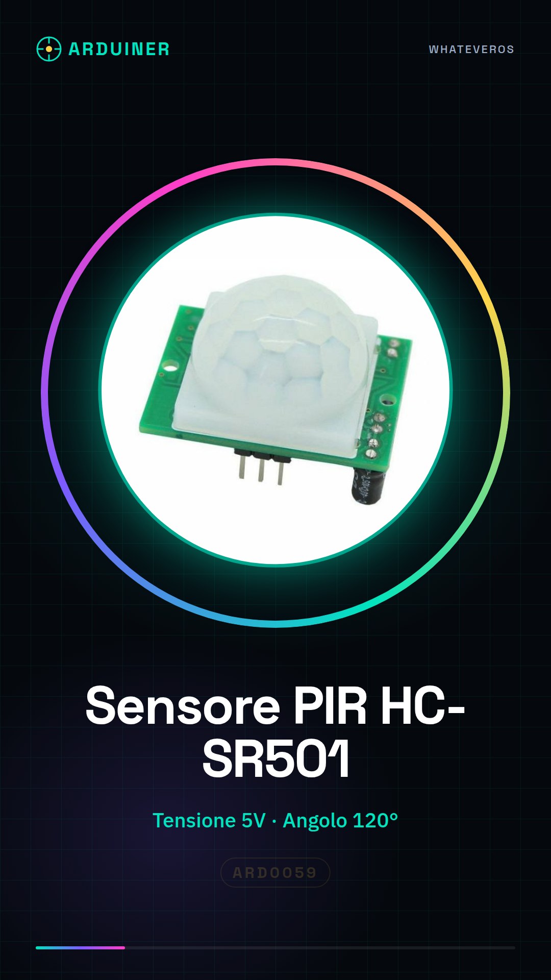
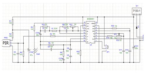
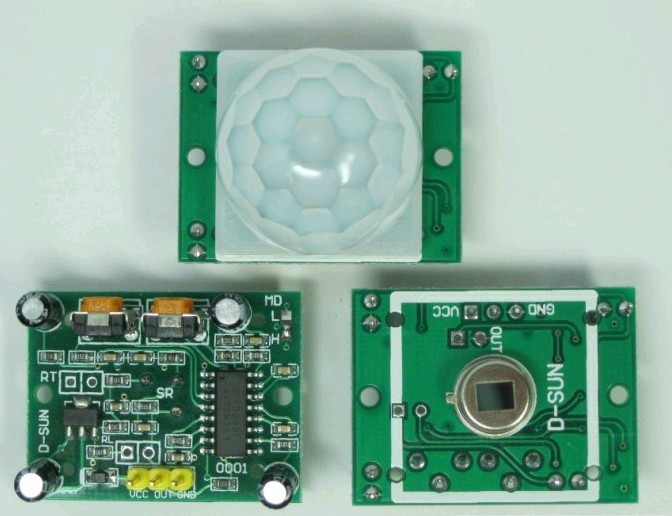
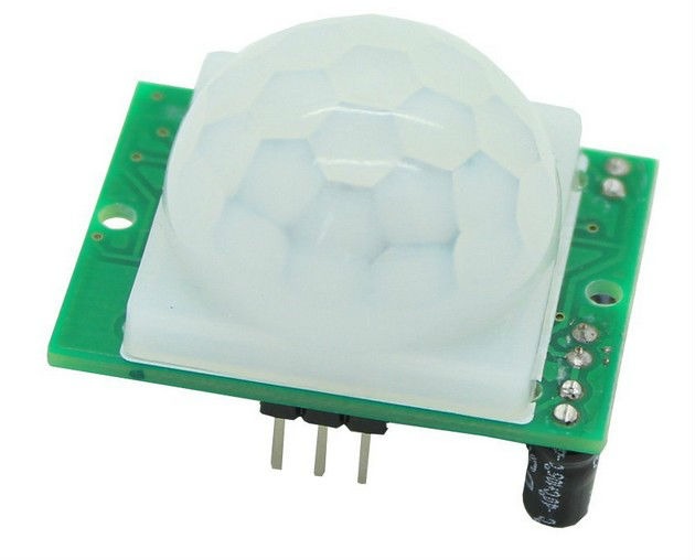
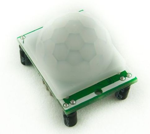
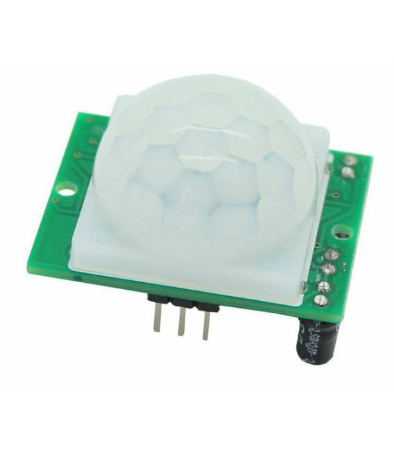
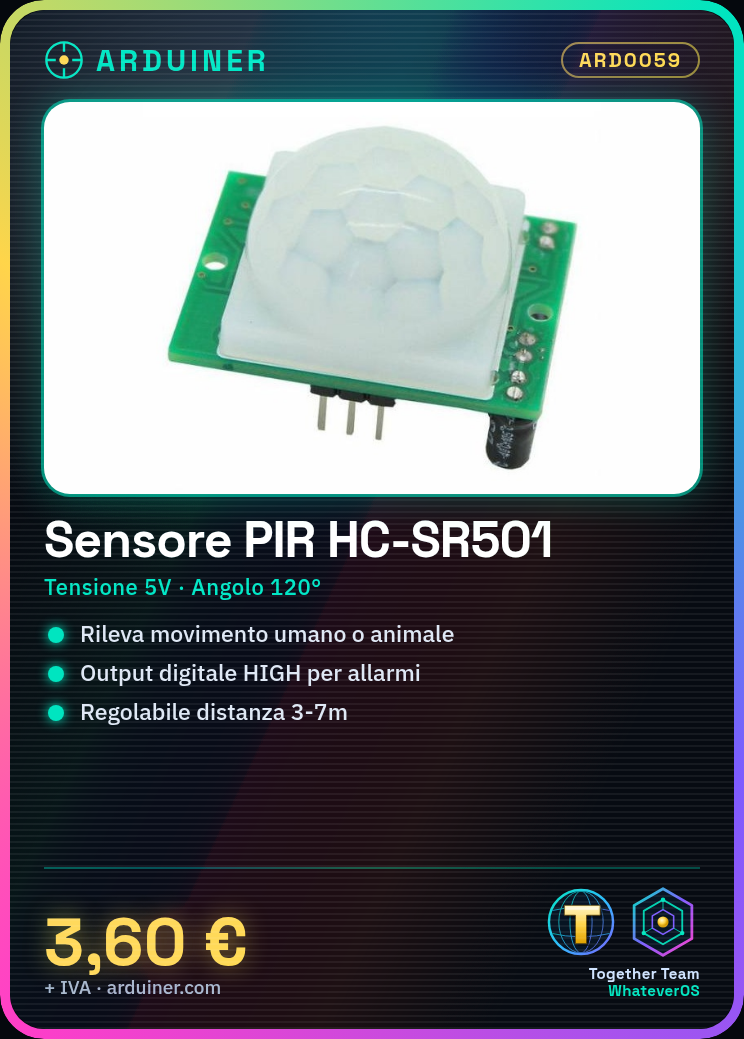
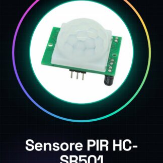
The HC-SR501 Infrared PIR Motion Sensor is a device that detects variations in heat caused by the movement of objects. Designed for use in home automation projects, security systems, and home automation applications, the sensor can detect movements within a 120° angle and at variable distances from 3 to 7 meters. The HC-SR501 provides a digital HIGH output when movement is detected, allowing connected devices such as alarms, lights, or other features to be activated.
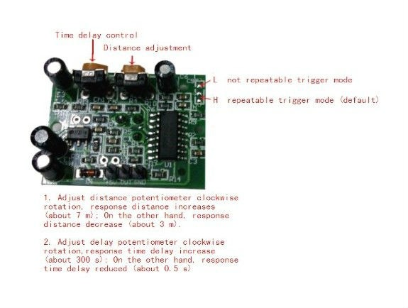
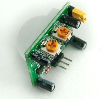
The sensor includes two potentiometers to adjust the delay time and detection range, allowing for a customized configuration based on project requirements. Additionally, a jumper allows the selection between repetitive and non-repetitive modes for the digital output, providing greater flexibility in the implementation of the device.
For the proper installation and operation of the sensor, it is necessary to correctly connect it to a DC power supply and a microcontroller such as Arduino. Configuring the sensor settings and choosing the operating mode are crucial for ensuring optimal performance.
Key Specifications
| Parameter | Value |
| Model | HC-SR501 |
| Supply Voltage | 4.5V – 20V DC (recommended 5V) |
| Current Consumption | ~50 µA |
| Detection Angle | ~120° |
| Detection Range | 3 – 7 meters (adjustable) |
| Activation Time | Adjustable (from ~3 to ~300 sec) |
| Delay Time | Adjustable |
| Operating Mode | Repetitive (H) or Non-Repetitive (L) |
| Digital Output (OUT) | HIGH (3.3V) when motion is detected |
| Container | N/D (see manufacturer’s technical sheet) |
| Quantity | 1 |
Installation and Usage
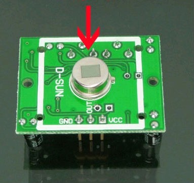
- Connect the VCC pin of the sensor to 5V of the power supply.
- Connect the GND pin of the sensor to GND of the power supply.
- Connect the OUT pin of the sensor to a digital pin of the Arduino.
- Adjust the potentiometer for the detection range based on project requirements.
- Adjust the potentiometer for the delay time based on project requirements.
Compatibility and Requirements
- The HC-SR501 sensor is compatible with Arduino and other microcontrollers that support digital connections.
- It can be used with home automation and smart home systems.
- Requires a DC power supply from 4.5V to 20V, with a recommended usage at 5V.
Limitations and Important Notes
- The sensor does not detect static objects or those without temperature variations.
- Detection sensitivity may vary in extreme weather conditions.
- It is necessary to correctly adjust the potentiometers to achieve the desired performance.
Troubleshooting
The detector does not detect motion.
Probable cause: The distance detection potentiometer is set to a value that is too low.
Solution: Increase the value of the distance detection potentiometer.
The detector constantly detects motion.
Probable cause: The distance detection potentiometer is set to a value that is too high.
Solution: Decrease the value of the distance detection potentiometer.
The detector does not provide a HIGH signal.
Probable cause: The delay time potentiometer is set to a value that is too high.
Solution: Decrease the value of the delay time potentiometer.
The detector continuously detects motion without pauses.
Probable cause: The time delay potentiometer is set to a value that is too low.
Solution: Increase the value of the time delay potentiometer.
Use cases
Home
Objective: To turn on the lights automatically when entering a room.
What’s needed: HC-SR501 detector, Arduino, LED, resistor.
Steps: 1) Connect the detector to Arduino. 2) Adjust the potentiometers. 3) Write the Arduino code to turn on the lights. 4) Test the system.
Expected result: The lights turn on automatically when entering a room.
Lab
Objective: To detect motion to activate a recording system.
What’s needed: HC-SR501 detector, Arduino, SD card.
Steps: 1) Connect the detector to Arduino. 2) Write the Arduino code to record data. 3) Test the system.
Expected result: The recording system is activated automatically when motion is detected.
Prototyping
Objective: Test the sensor’s reactivity.
What’s needed: HC-SR501 sensor, Arduino, LED.
Steps: 1) Connect the sensor to Arduino. 2) Write Arduino code to turn on an LED. 3) Test the system.
Expected result: The LED turns on when motion is detected.
School
Objective: Educate them on the use of sensors.
What’s needed: HC-SR501 sensor, Arduino, LED.
Steps: 1) Connect the sensor to Arduino. 2) Write Arduino code to turn on an LED. 3) Test the system.
Expected result: Students learn to use sensors to activate devices.
Maintenance
Objective: Verify the sensor’s functionality.
What’s needed: HC-SR501 sensor, Arduino, LED.
Steps: 1) Connect the sensor to Arduino. 2) Write Arduino code to turn on an LED. 3) Test the system.
Expected result: The system correctly verifies the sensor’s functionality.
Repair
Objective: Repair a security system.
What you need: HC-SR501 detector, Arduino, LED.
Steps: 1) Connect the detector to Arduino. 2) Write the Arduino code to turn on an LED. 3) Test the system.
Expected result: The security system is repaired correctly.
Automation
Objective: Activate a security system.
What you need: HC-SR501 detector, Arduino, relay.
Steps: 1) Connect the detector to Arduino. 2) Write the Arduino code to activate the relay. 3) Test the system.
Expected result: The security system is activated automatically when movement is detected.
Testing
Objective: Verify the performance of the detector.
What you need: HC-SR501 detector, Arduino, LED.
Steps: 1) Connect the detector to Arduino. 2) Write the Arduino code to turn on an LED. 3) Test the system.
Expected result: The system correctly verifies the performance of the detector.
In the package
- 1 HC-SR501 detector
Complete the project
- 4 Pieces 38Khz IR LED Receiver Universal TL1838 VS1838B arduino compatible: To connect the detector to a home automation system.
Technical FAQs
How to adjust the delay time of the detector?
Use the dedicated potentiometer to adjust the delay time.
Why does the detector not detect movement?
Check the potentiometer settings and pin configuration.
What are the dimensions of the detector?
N/D (see manufacturer’s datasheet).
Which microcontrollers are compatible with the detector?
Arduino and other microcontrollers that support digital connections.
Tutorial: How to use PIR HC-SR501 Motion Detector
The HC-SR501 PIR motion detector is an essential component for projects requiring human motion detection. Ideal for both beginners and more experienced makers, this detector can be used in various domestic and industrial applications. This tutorial will guide you through the necessary steps to connect the detector to your Arduino and run a simple test project.
What you need
- Arduino Uno or compatible
- USB cable
- HC-SR501 PIR sensor
Steps
- Connect the following pins of the PIR sensor to those of the Arduino: VCC to 5V, GND to ground, OUT to digital pin 2.
- Open Arduino IDE and create a new sketch.
- Insert the following code into your sketch:
- Upload the sketch to your Arduino.
- Observe the output in Serial Monitor to see when the sensor detects motion.
Example code
const int pirPin = 2; // pin di output del sensore PIR
void setup() {
  pinMode(pirPin, INPUT);
  Serial.begin(9600);
}
void loop() {
  if (digitalRead(pirPin) == HIGH) {
    Serial.println("Movimento rilevato!");
  }
}
Mini project
Create a home security system that sends a notification when the PIR sensor detects motion. You can use an online service like IFTTT to send messages or emails.
Common mistakes
- The sensor does not respond: check the connections and power supply voltage.
- False movements: adjust the range of the sensor according to your needs.
- No output in Serial Monitor: check if you have correctly set the PIR pin output as HIGH.
- The code does not load: make sure the USB driver is installed and the serial port is selected correctly
Recommended accessories
- Relay Module
- LCD Display 16×2
- Buzzer
- RGB LED
Frequently asked questions
How can I adjust the detection area of the sensor?
Check the datasheet to find specific information on how to configure the distance and detection field.
The sensor responds too slowly
Check the datasheet to set the sensor’s wait times correctly.
Reviews
There are no reviews yet.