 EN
 IT Italiano
 ES Español
 FR Français
 DE Deutsch
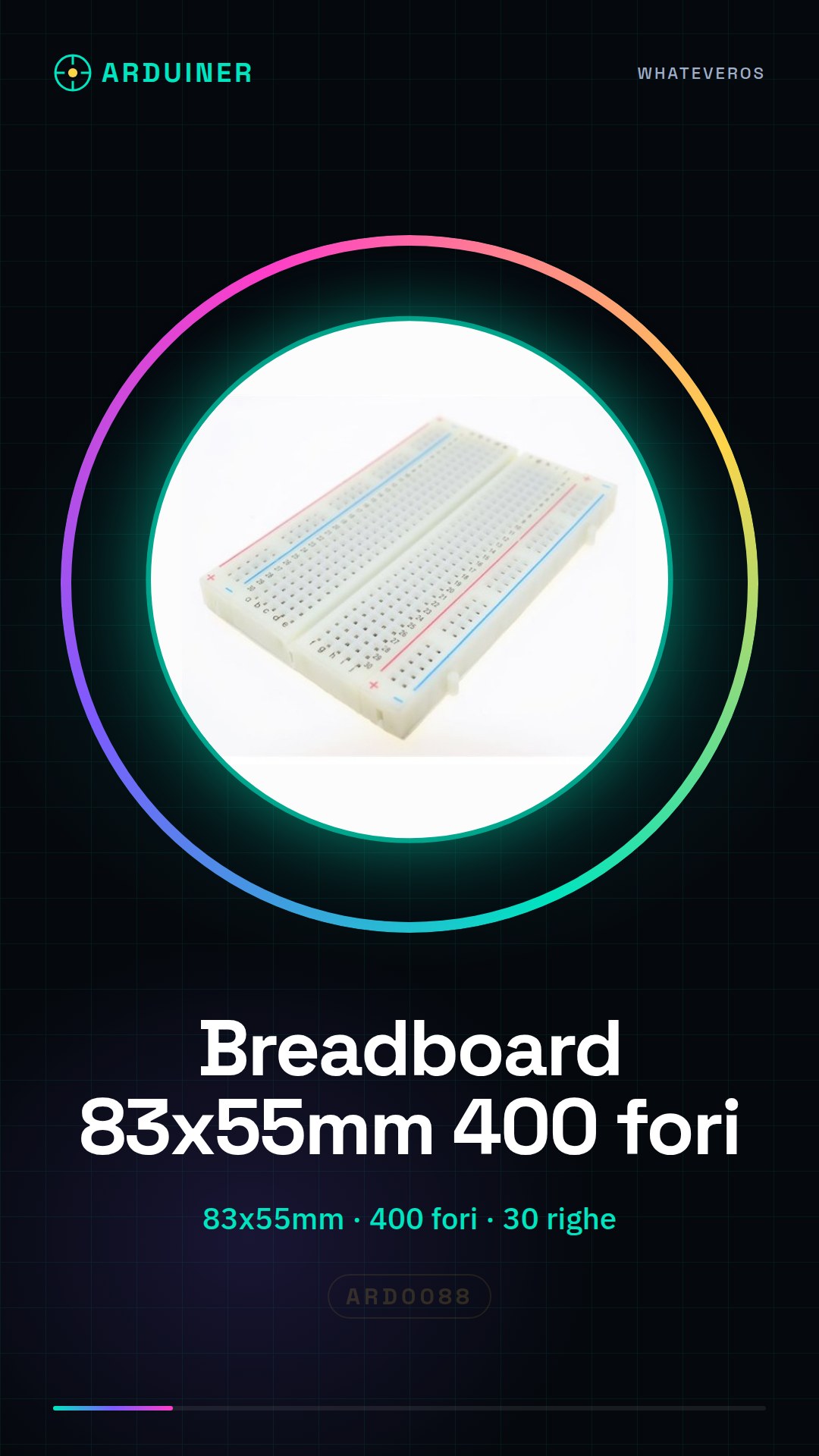
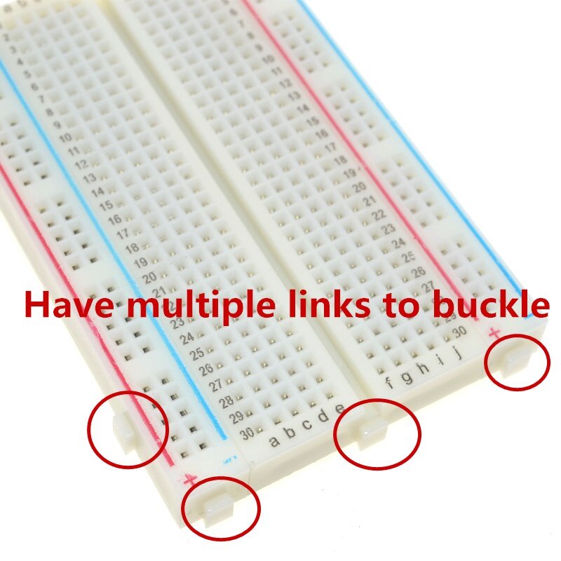
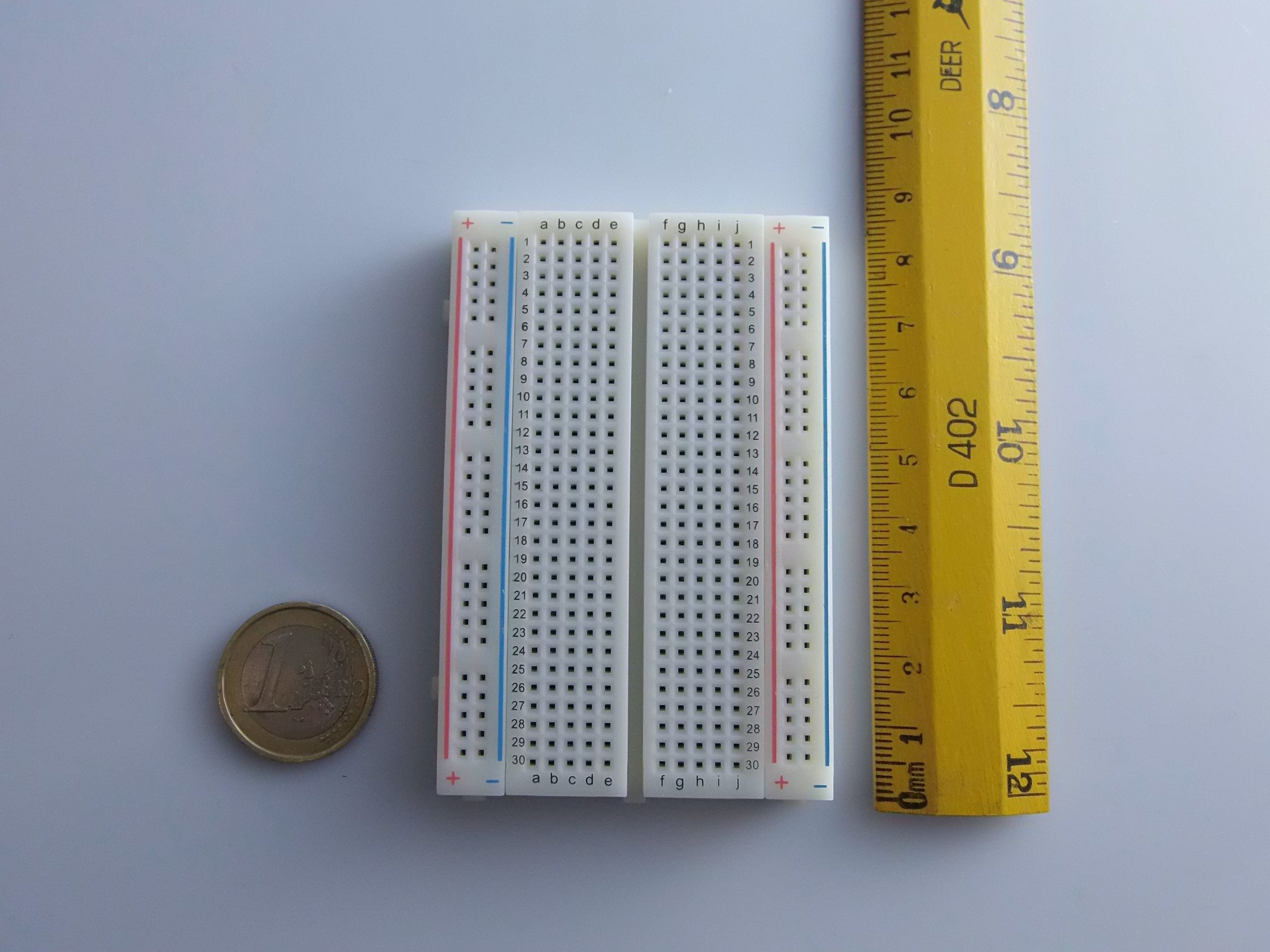
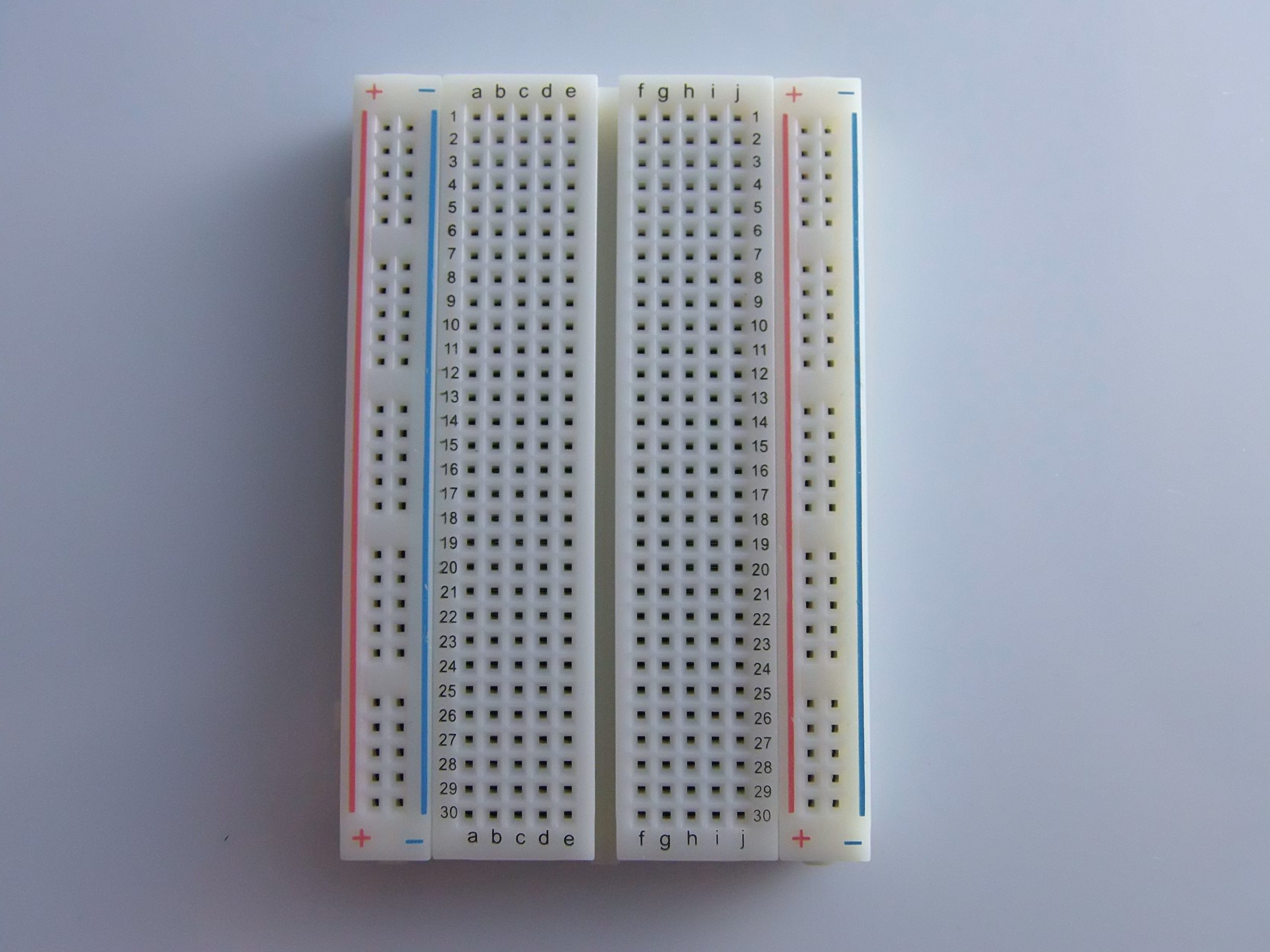
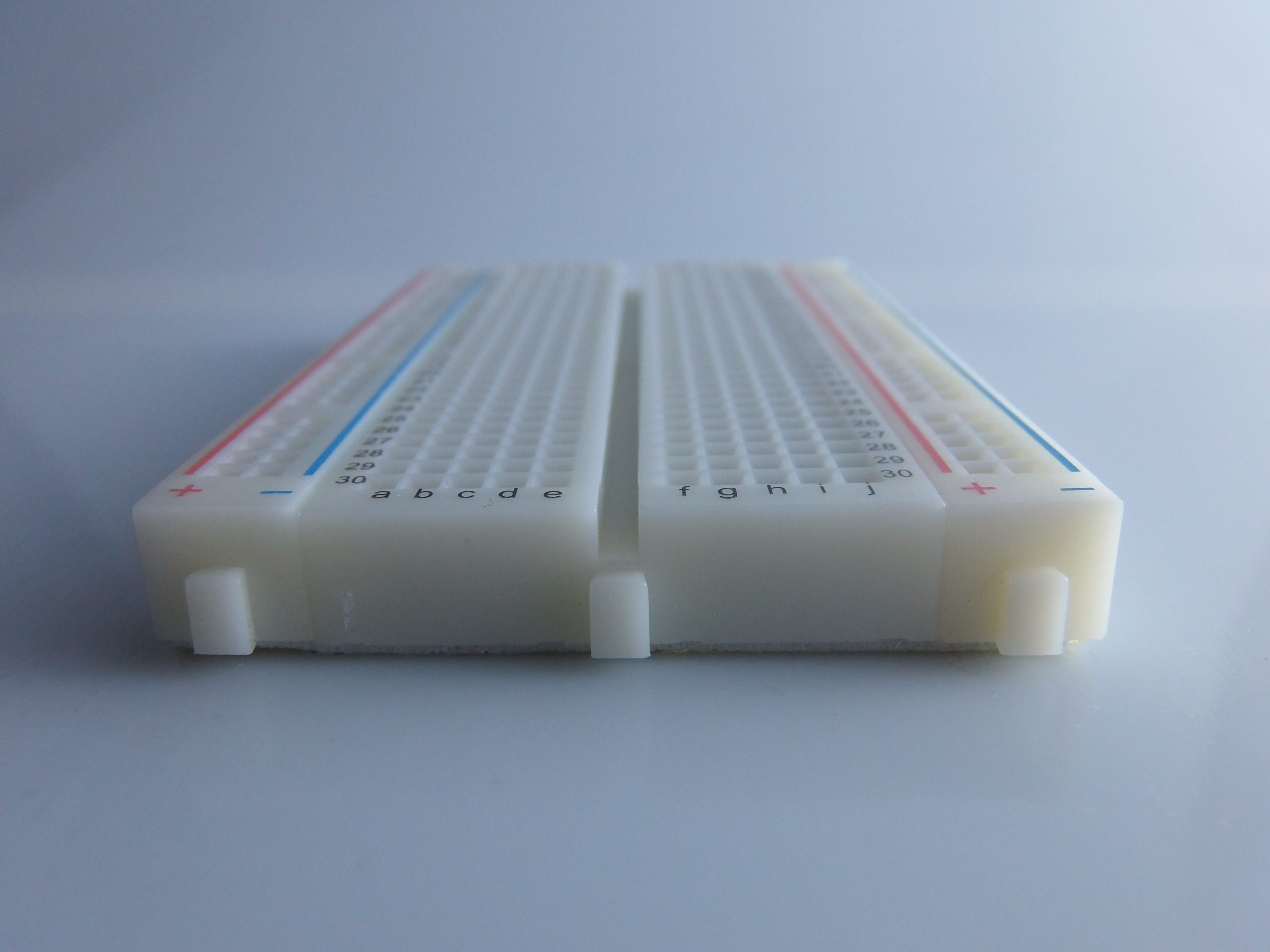
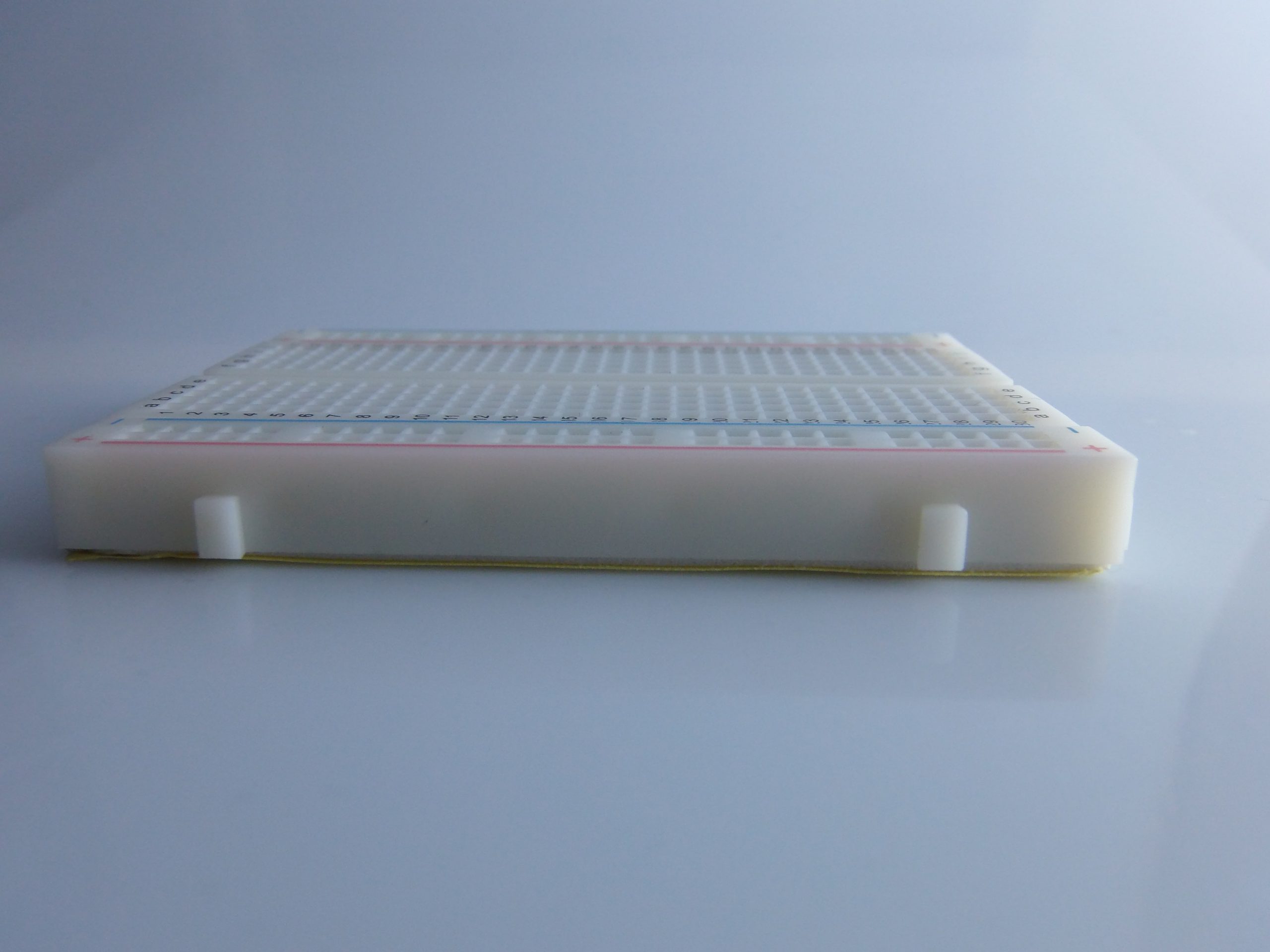
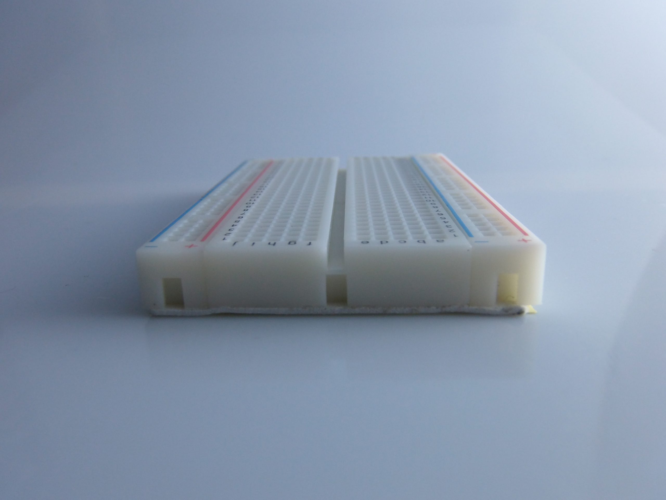
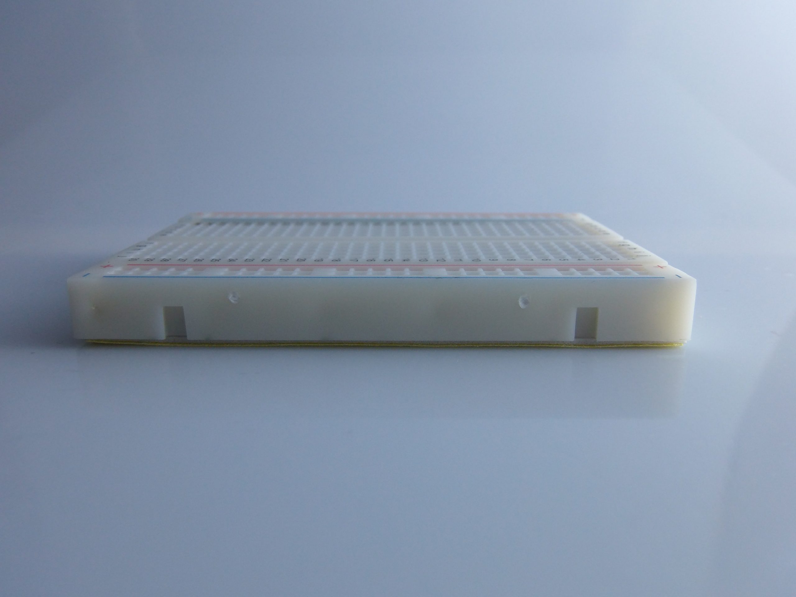
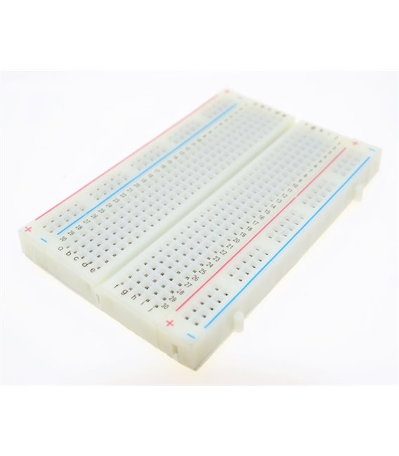
Description
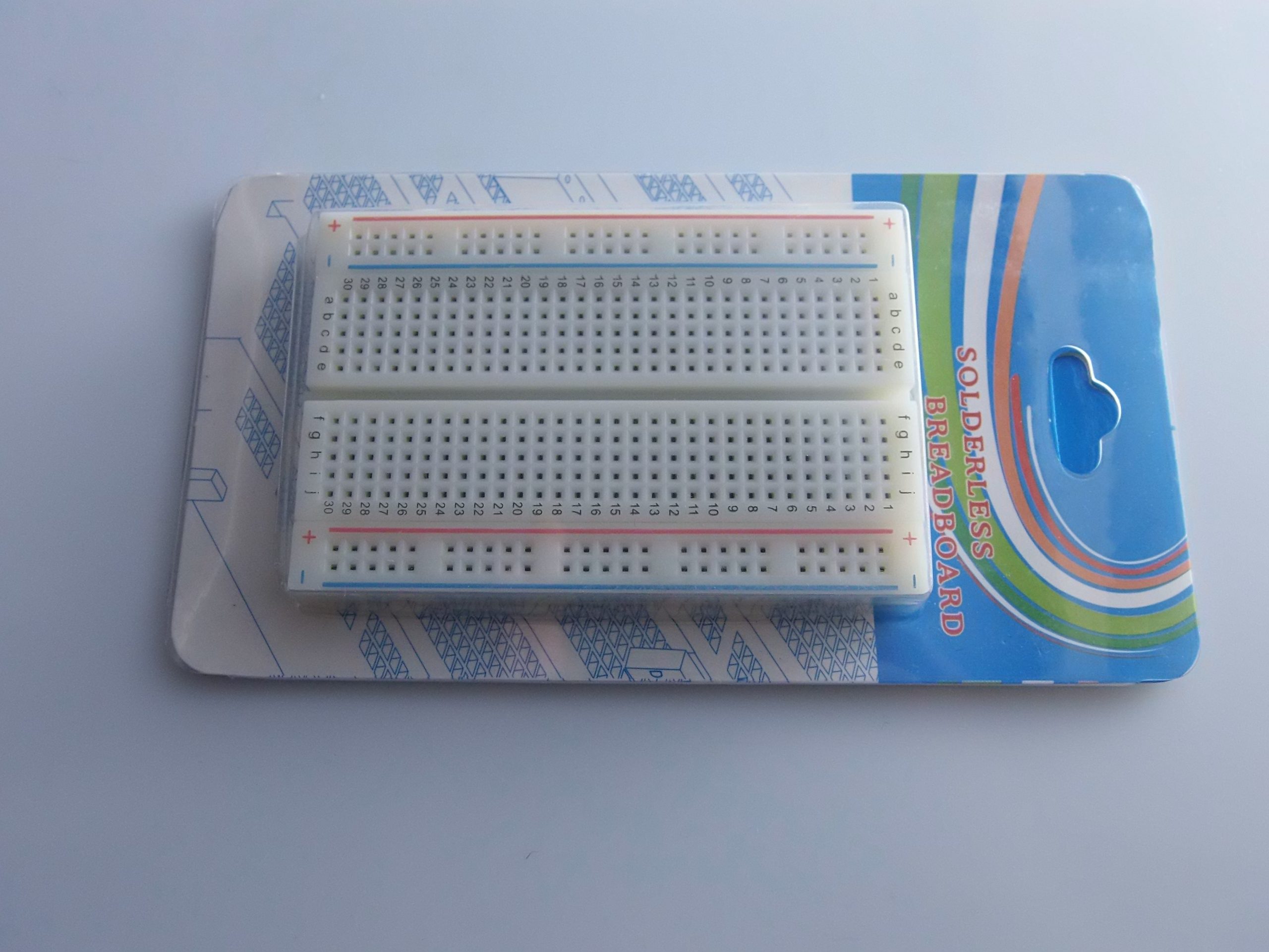
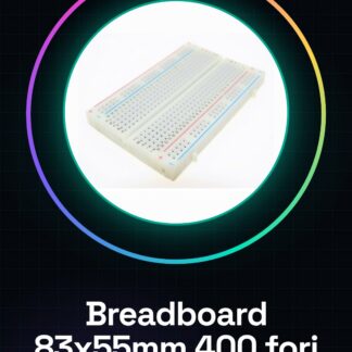
🔧 Module Description Breadboard 83x55mm 400 holes
Technical Specifications:
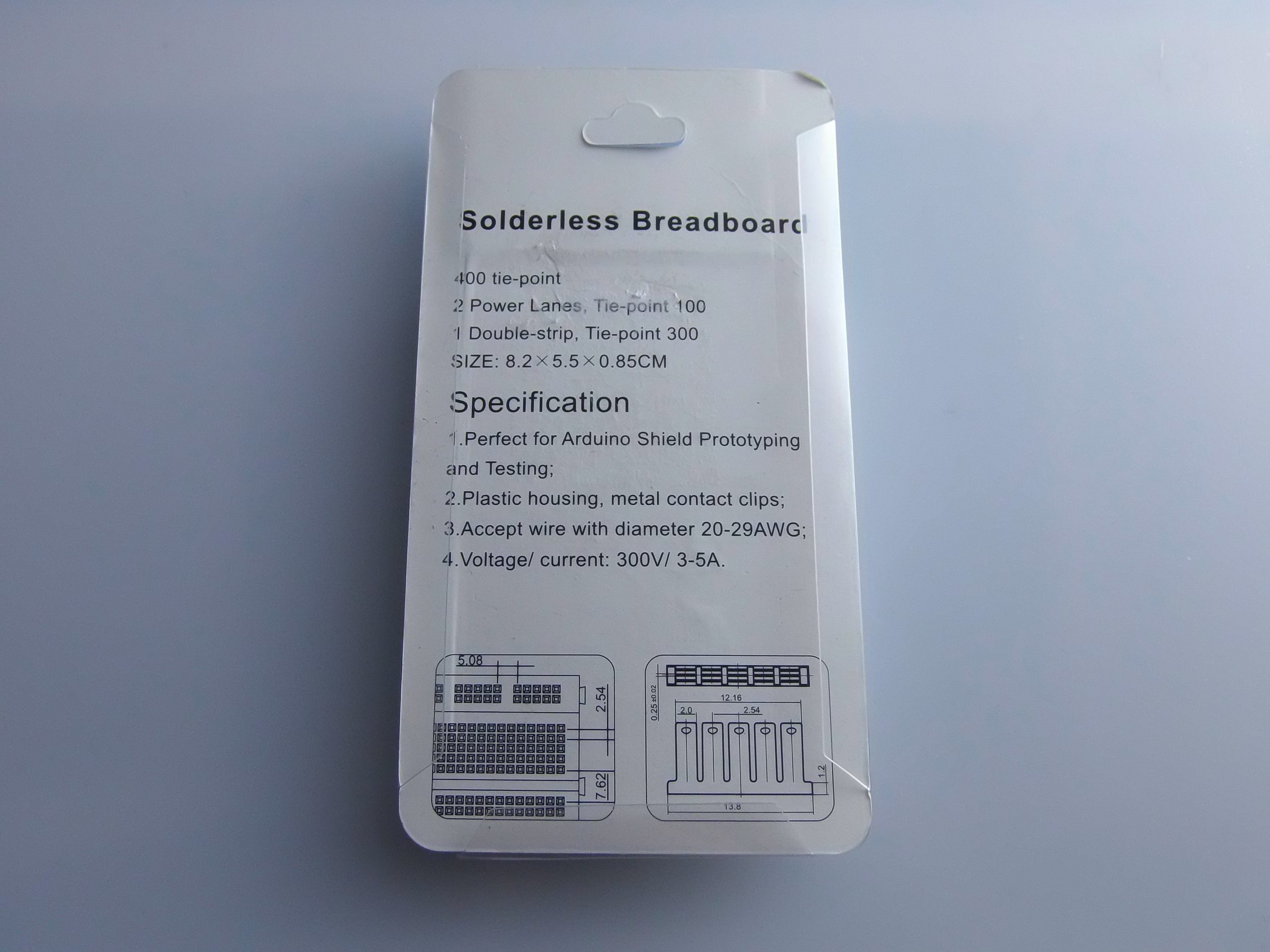
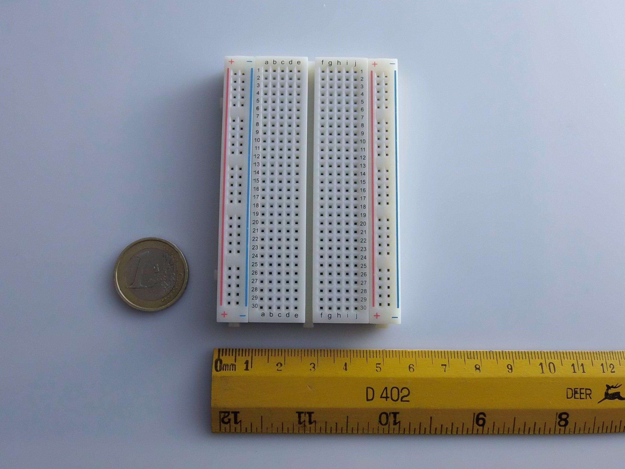
- Dimensions: 83 mm (length) x 55 mm (width)
- Number of holes: 400 total contacts
- Distribution:
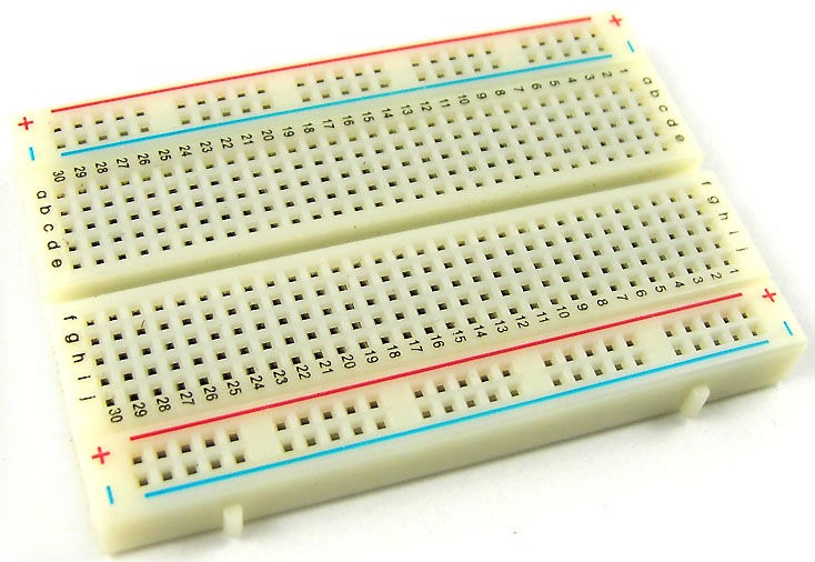
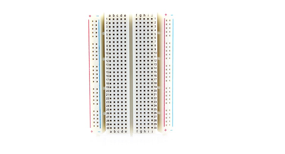
- 2 power rails (red and blue) at the sides
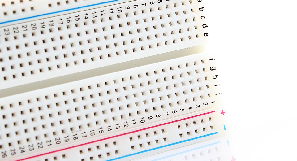
- 30 rows x 10 columns of central holes, arranged in two groups of 5 (for component connections)
- Material: Flame-retardant ABS plastic with internal metal contacts (typically nickel or phosphor bronze)
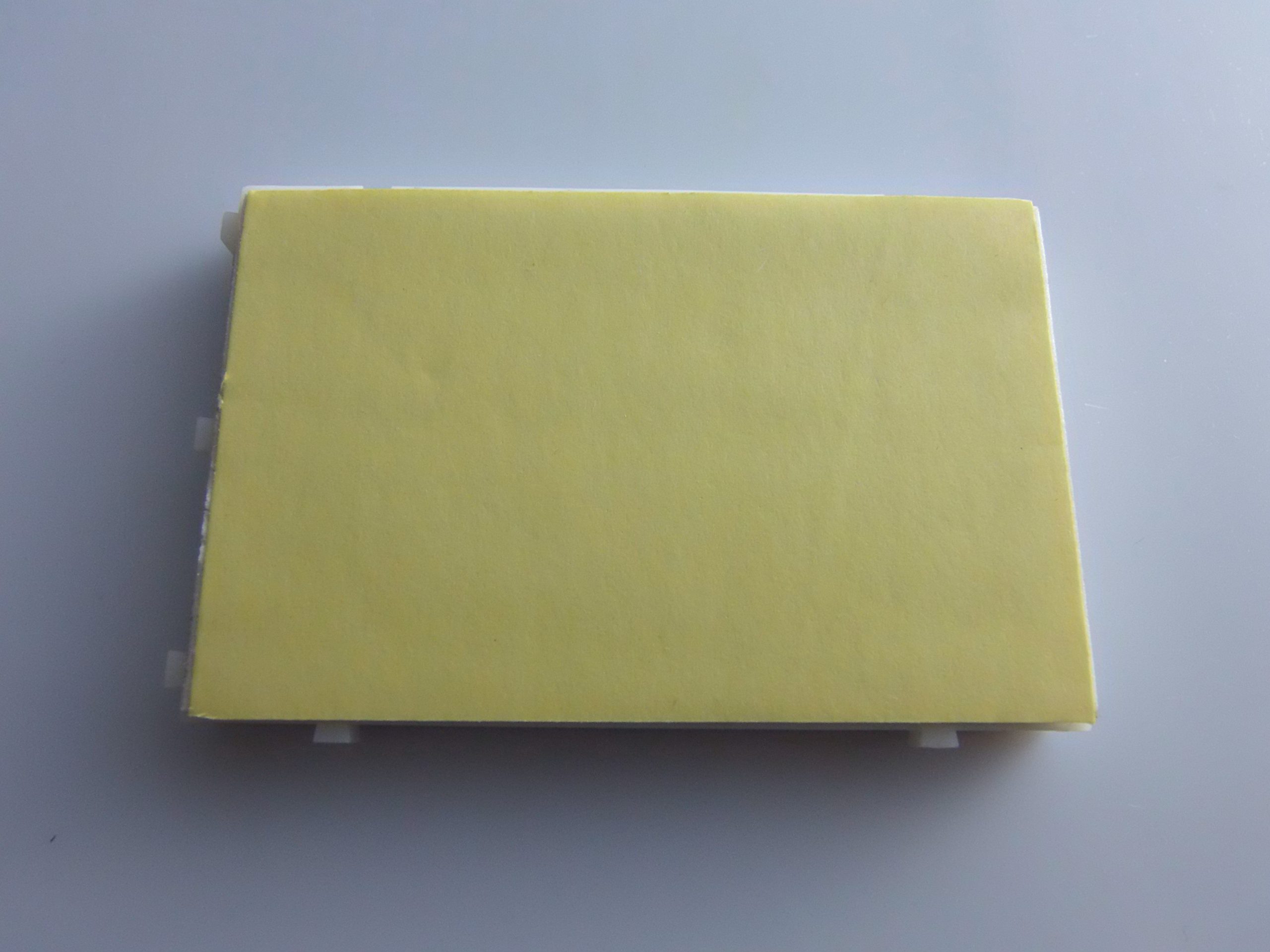
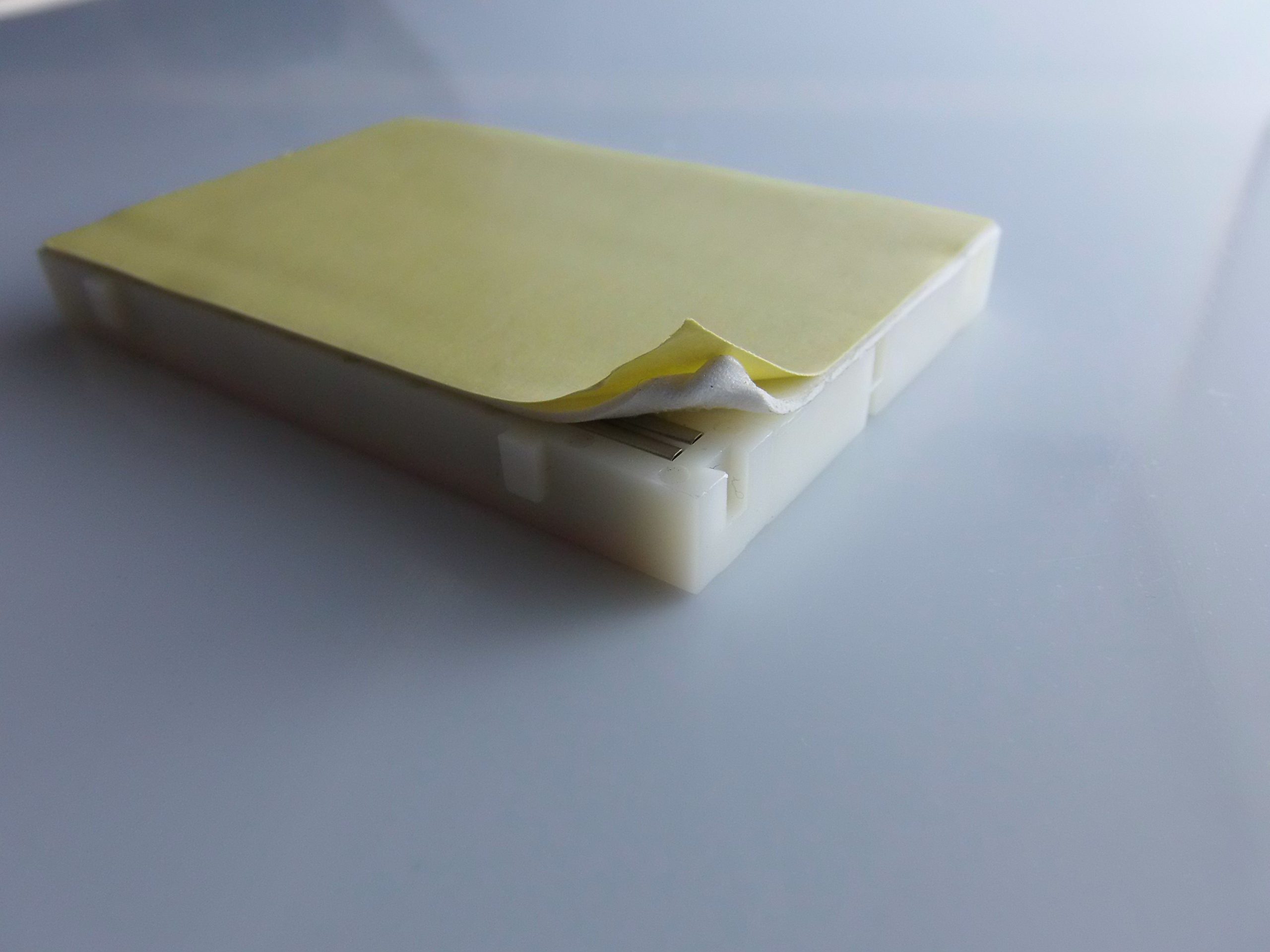
- Adhesive backing: Usually equipped with a backing adhesive for mounting on surfaces or modular bases
- Compatibility: Compatible with male-male jumper wires from 22-28 AWG, microcontrollers such as Arduino UNO, Mega, Nano, etc.
Advantages:
- Infinite reuse
- No soldering required (ideal for prototyping)
- Great for students, makers, and hobbyists
- Allows for quick circuit modifications
📘 Guide to Using a Breadboard with Arduino
🔌 1. Basic Connections: how the breadboard works
- The outer horizontal rows (usually marked with red + and blue -) are internally connected along the entire length: ideal for VCC (5V) and GND.
- The central vertical columns are divided into two groups of 5 holes (on each side of the central slot). These holes are electrically connected vertically.
Example:
Fori 1A-1E sono collegati insieme.
Fori 1F-1J sono collegati insieme.
Ma 1E ≠ 1F (divisi dalla scanalatura centrale).
⚙️ 2. Connection with Arduino: basic diagram
Components required:
- 1 x Arduino UNO
- 1 x Breadboard 400 holes
- Male-male jumper
- 1 x LED
- 1 x 220 ohm resistor
- 1 x Button (optional)
Schematic:
[LED Blink]

Arduino:
- PIN 13 → Resistenza 220Ω → Anodo LED (gamba lunga)
- Catodo LED (gamba corta) → GND

Collegamento sulla breadboard:
- Inserire il LED con le gambe in due file diverse
- Collegare una resistenza a una gamba e poi al pin 13 tramite jumper
- Collegare l’altra gamba al rail GND
💻 Example 1: Basic Blink LED Program
// Blink LED collegato al pin 13
void setup() {
  pinMode(13, OUTPUT); // imposta il pin 13 come output
}

void loop() {
  digitalWrite(13, HIGH); // accende il LED
  delay(1000);            // attende 1 secondo
  digitalWrite(13, LOW);  // spegne il LED
  delay(1000);            // attende 1 secondo
}
Load the code via Arduino IDE, and the LED will blink every second.
💻 Example 2: Button to Turn On an LED
Additional components:
- 1 x Button
- 1 x 10kΩ resistor (pull-down)
Connection:
- LED as before
- Button: one leg to 5V, the other to pin 2 of Arduino and also a 10kΩ resistor to GND
Code:
int led = 13;
int pulsante = 2;
int stato = 0;

void setup() {
  pinMode(led, OUTPUT);
  pinMode(pulsante, INPUT);
}

void loop() {
  stato = digitalRead(pulsante);

  if (stato == HIGH) {
    digitalWrite(led, HIGH);  // accende LED
  } else {
    digitalWrite(led, LOW);   // spegne LED
  }
}
💡 Practical Tips
- Use jumper wires of different colors to distinguish signals (e.g., red for VCC, black for GND, yellow/blue for signals).
- Use the side rail to distribute 5V and GND to multiple components.
- Be careful with the internal connection of the holes to avoid short circuits.
🧪 Projects you can build on the breadboard with Arduino:
- Traffic Light (red/yellow/green LEDs in sequence)
- Temperature Sensor with LM35
- PIR Motion Sensor
- 16×2 LCD Display with I2C
- Servo Motor Control
- Sound Alarm with buzzer and light sensor
📦 In summary:
| Feature | Detail |
|---|---|
| Type | Solderless Breadboard |
| Dimensions | 83 x 55 mm |
| Number of Holes | 400 |
| Compatibility | Arduino, Raspberry Pi, etc. |
| Usage | Quick prototyping and testing |
| Connection | Male-Male Jumper |
Tutorial: How to use 83x55mm Breadboard
The breadboard is a fundamental tool for makers and electronics students. It allows for temporary testing of circuits without the use of soldering, making quick prototyping and debugging possible.
What you need
- Arduino
- jumper wires
- electronic components (resistors, LEDs, transistors)
- multimeter
Steps
- Step 1: Arrange the breadboard on the table so that it is stable and accessible.
- Step 2: Check the arrangement of the holes in the breadboard. The holes are organized into columns of five, separated by two central rows without vertical connection.
- Step 3: Connect jumper wires between the Arduino and the breadboard to supply power to the components.
- Step 4: Insert an electronic component (such as a resistor) into two holes in the same column.
- Step 5: Connect an LED to the breadboard, making sure to understand the polarity of the LED (long leg towards GND).
- Step 6: Use jumper wires to connect the circuit between the Arduino and other components.
- Step 7: Test the circuit with a multimeter to verify correct connections.
- Step 8: Once satisfied, you can remove the components from the breadboard without damaging them.
Mini project
Create a simple lamp controlled by a button. Connect the button and the LED to the breadboard to create a circuit that turns the LED on or off when the button is pressed.
Common mistakes
- Insert components into the breadboard with incorrect polarity
- Connect two columns of holes instead of the same column
- Do not test connections before activating the Arduino
Recommended accessories
- Jumper wires
- Basic Arduino kit
- Variable resistor set
- Multicolor LEDs
Frequently asked questions
What is the difference between a breadboard and a prototype board?
The breadboard does not require soldering, making it easier to test and modify circuits. The prototype board, on the other hand, allows for the creation of permanent circuits.
Can I use a breadboard with any electronic component?
Yes, but make sure that the components have the appropriate pins to be inserted into the breadboard holes.
Reviews
There are no reviews yet.