 EN
 IT Italiano
 ES Español
 FR Français
 DE Deutsch
Description
Technical Description
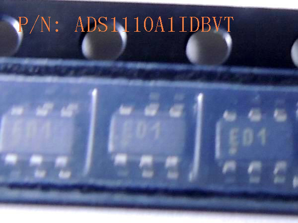
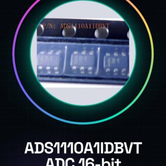
The ADS1110A1IDBVT is a 16-bit delta-sigma analog-to-digital converter (ADC) that allows data acquisition from analog signals. This component is designed for applications requiring high precision and resolution, such as voltage and current measurement.
The ADC operates at a sampling rate of 0.128 KSPS, providing digital data with a 16-bit resolution. The ADS1110A1IDBVT uses the I2C interface for communication with microcontroller systems.
The ADS1110A1IDBVT is suitable for projects that require accurate conversion of analog signals to digital data, such as reading temperature, pressure, or other types of analog signal-generating sensors.
Key Specifications
| Parameter | Value |
| Model | ADS1110A1IDBVT |
| Number of Pieces | 1 |
| ADC Type | Delta-Sigma |
| Resolution | 16 bit |
| Sampling Frequency | 0.128 KSPS |
| Interface | I2C |
| Power Supply | N/D (see manufacturer’s datasheet) |
| Dimensions | N/D (see manufacturer’s datasheet) |
| Package | N/D (see manufacturer’s datasheet) |
Installation and Usage
- Connect the VCC pin of the module to an appropriate power supply.
- Connect the GND pin of the module to the GND of the system.
- Connect the SDA and SCL pins of the module to the corresponding SDA and SCL pins of the microcontroller.
- Configure the I2C address of the device in the programming code.
- Initialize the ADC converter in the programming code.
Compatibility and Requirements
- The ADS1110A1IDBVT is compatible with microcontrollers that support the I2C interface, such as Arduino.
- A specific library is required to communicate with the ADC converter.
- A pull-up circuit is required for I2C communication.
Important Limits and Notes
- The ADS1110A1IDBVT does not support simultaneous reading of multiple channels.
- The configuration of power supply and I2C address is critical for the proper functioning of the device.
- Using a high voltage power supply can damage the ADC converter.
Troubleshooting
The ADC converter does not respond.
Probable cause: The power supply pin is not correctly connected.
Solution: Check the connection of the VCC and GND pins.
The acquired values are incorrect.
Probable cause: The I2C address of the device is not correctly configured.
Solution: Verify and configure the I2C address in the programming code.
The ADC converter does not respond to the I2C command.
Probable cause: The pull-up circuit is not present or not correctly configured.
Solution: Add a pull-up circuit to the SDA and SCL pins.
The acquired data is always zero.
Probable cause: The analog signal is not properly connected.
Solution: Check the connection of the analog signal to the ADC converter.
Use cases
Temperature Sensor
Objective: Measure ambient temperature.
What’s needed: NTC 10kΩ Thermistor, ADS1110A1IDBVT, Arduino Uno.
Steps: 1) Connect the NTC thermistor to the ADC converter. 2) Configure the I2C address of the device. 3) Initialize the ADC converter in the programming code. 4) Read data from the ADC converter and convert it to degrees Celsius.
Expected result: The system measures ambient temperature and displays it on a screen.
Current Measurement
Objective: Measure current in a circuit.
What’s needed: Current sensing resistor, ADS1110A1IDBVT, Arduino Uno.
Steps: 1) Connect the current sensing resistor to the ADC converter. 2) Configure the I2C address of the device. 3) Initialize the ADC converter in the programming code. 4) Read data from the ADC converter and calculate the current.
Expected result: The system measures the current in a circuit and displays it on a screen.
Voltage monitoring
Objective: Monitor the supply voltage.
Required: ADS1110A1IDBVT, Arduino Uno.
Steps: 1) Connect a voltage sensor to the ADC converter. 2) Configure the I2C address of the device. 3) Initialize the ADC converter in the programming code. 4) Read data from the ADC converter and display the voltage.
Expected result: The system monitors the supply voltage and displays it on a screen.
Light sensor
Objective: Measure light intensity.
Required: Photodiode, ADS1110A1IDBVT, Arduino Uno.
Steps: 1) Connect the photodiode to the ADC converter. 2) Configure the I2C address of the device. 3) Initialize the ADC converter in the programming code. 4) Read data from the ADC converter and convert it to light level.
Expected result: The system measures the light intensity and displays it on a screen.
Pressure Sensor
Objective: Measure atmospheric pressure.
Required: Pressure sensors, ADS1110A1IDBVT, Arduino Uno.
Steps: 1) Connect the pressure sensor to the ADC converter. 2) Configure the I2C address of the device. 7) Initialize the ADC converter in the programming code. 4) Read data from the ADC converter and convert it to pressure.
Expected result: The system measures atmospheric pressure and displays it on a screen.
Humidity Sensor
Objective: Measure relative humidity.
Required: Humidity sensors, ADS1110A1IDBVT, Arduino Uno.
Steps: 1) Connect the humidity sensor to the ADC converter. 2) Configure the I2C address of the device. 3) Initialize the ADC converter in the programming code. 4) Read data from the ADC converter and convert it to humidity.
Expected result: The system measures relative humidity and displays it on a screen.
Motion sensor
Objective: Detect the presence of motion.
Required: Motion sensors, ADS1110A1IDBVT, Arduino Uno.
Steps: 1) Connect the motion sensor to the ADC converter. 2) Configure the I2C address of the device. 3) Initialize the ADC converter in the programming code. 4) Read data from the ADC converter and detect motion.
Expected result: The system detects the presence of motion and displays it on a screen.
Distance sensor
Objective: Measure distance.
Needed: Distance sensors, ADS1110A1IDBVT, Arduino Uno.
Steps: 1) Connect the distance sensor to the ADC converter. 2) Configure the I2C address of the device. 3) Initialize the ADC converter in the programming code. 4) Read data from the ADC converter and convert it to distance.
Expected result: The system measures the distance and displays it on a display.
In the package
- 1 piece
Complete the project
- ADS1115 16 Bit I2C Analog to Digital Converter ADC 4 Channels with Programmable Gain Amplifier: For I2C communication.
- 6 Pieces 74HC595N Shift Registers for Counters 8-BIT IC Integrated Circuits: To amplify the analog signal.
Technical FAQs
Where can I find the datasheet for the ADS1110A1IDBVT?
The datasheet is available on the Texas Instruments website.
Can it read multiple channels simultaneously?
No, the ADS1110A1IDBVT cannot read multiple channels simultaneously.
How do I verify the correct I2C address of the device?
Check the I2C address of the device in the programming code and configure it correctly.
Which power pins do I need to connect?
Connect the VCC pin of the module to an appropriate power source and the GND pin to the GND of the system.
Tutorial: How to use ADS1110A1IDBVT
The ADS1110A1IDBVT is a 16-bit delta-sigma analog-to-digital converter (ADC) that allows data acquisition from analog signals. It is ideal for Arduino projects where precise voltage measurements are required.
What you need
- Arduino Uno or compatible
- USB A-B cable
- Connection between ADC and Arduino
- Required library
Steps
- Install the ADS1x10 library for the ADS1110A1IDBVT from GitHub.
- Connect the VCC of the module to 3.3V of the Arduino.
- Connect the GND of the module to the GND of Arduino.
- Connect SDA and SCL of the module to the I2C pins (SDA=4, SCL=5) of Arduino.
- Configure the I2C address of the device in the code (check the datasheet).
- Initialize the ADC converter in the application.
- Read data from the converter and print it in serial or on a display.
- Verify the correctness of the acquired values with measurement tools.
Example code
// Esempio di codice per leggere il valore del convertitore ADS1110A1IDBVT
#include <ADS1x10.h>
ADS1110 ads;
void setup() {
  Serial.begin(9600);
  ads.begin();
}
void loop() {
  int value = ads.readADC();
  Serial.println(value);
}
Mini project
Create a temperature sensor that reads data from the thermistor and converts it to degrees Celsius.
Common mistakes
- Do not verify the correct I2C address of the device.
- Ignore the configuration of the power supply pins (3.3V).
- Omit the connection between SDA/SCL and the respective pins of Arduino.
- Forget to install the necessary library for the ADS1110A1IDBVT.
Recommended accessories
- NTC Thermistor 10kΩ
- I2C LCD Display
- 4.7kΩ Pull-up Resistor
- Audio Jack for Analog Signals
Frequently asked questions
Where can I find the datasheet for the ADS1110A1IDBVT?
The datasheet is available on the Texas Instruments manufacturer website.
Can it read multiple channels simultaneously?
No, the ADS1110A1IDBVT is a single-channel converter.
Reviews
There are no reviews yet.