 EN
 IT Italiano
 ES Español
 FR Français
 DE Deutsch
Description
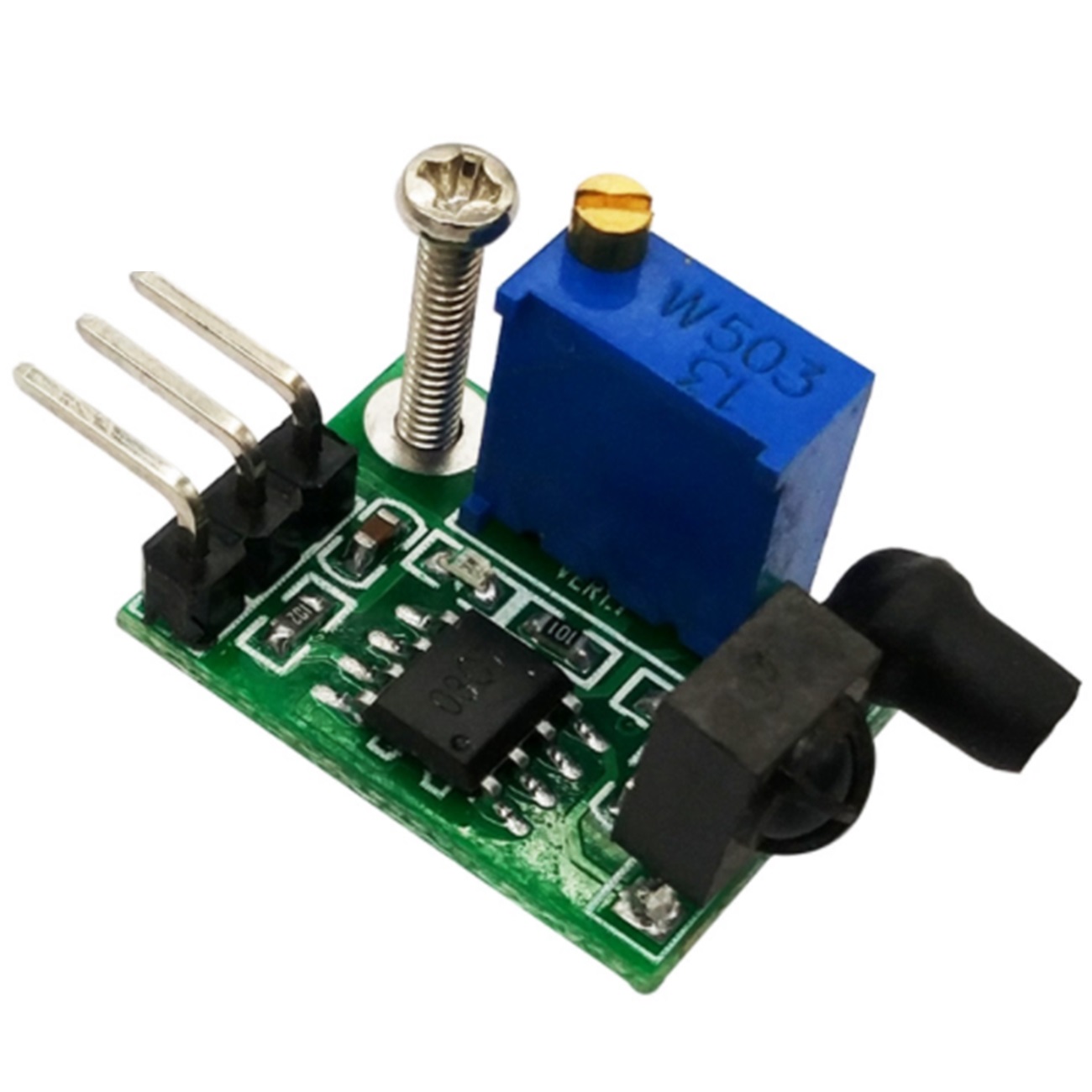
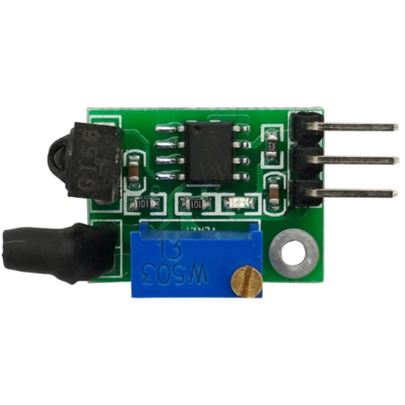
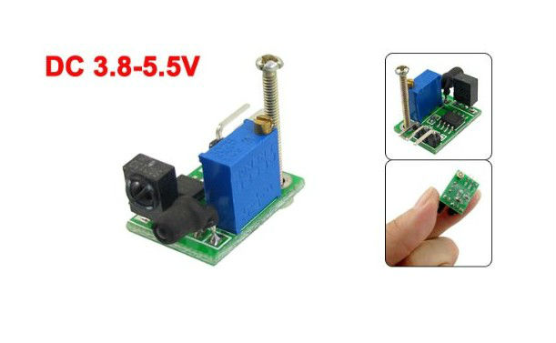
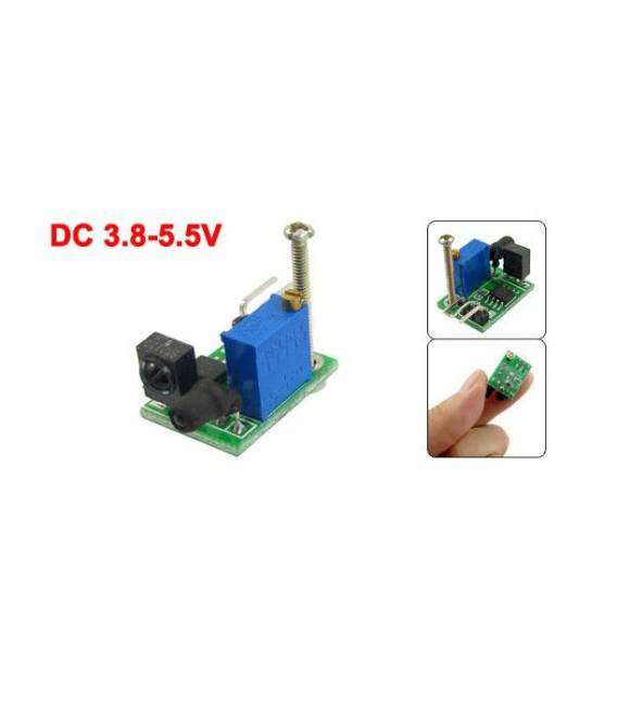
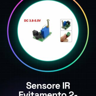
Digital infrared obstacle avoidance sensors, ultra-compact, adjustable current 6mA for 3-100cm range In stock new
How it works: the sensor emits infrared light detection, based on reflection, if it detects an obstacle, the pin OUT output is 0, otherwise 1.
Operating voltage: 3.8 v-5.5 v
Operating current (at 5 V): typical current 6 mA
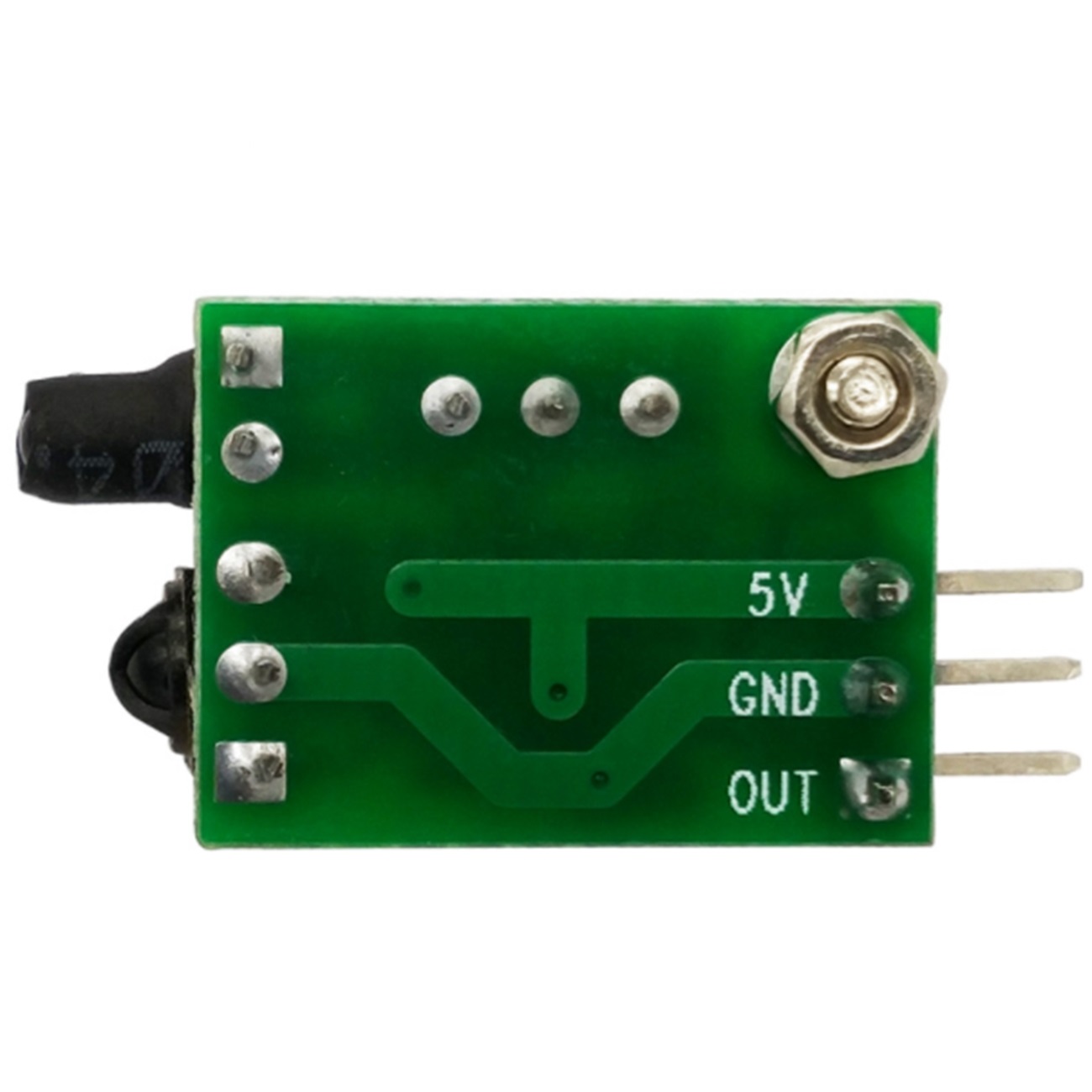
Input and output signals (3 lines):
VCC GND OUT
GND, power supply VCC, the VCC range 3.8v-5.5v
The following is the actual detection range of the field test:
Detection range (test environment, indoor, when the maximum power supply voltage is 5v power consumption is 6.5ma):
(1) white wall: 100 cm
(2) black IBM computer cover: 20 cm
(3) fingers: 18 cm
(4) palm of the hand: 30 cm
(5) a transparent ballpoint pen: 20 cm
A transparent ballpoint pen can be sensitive to detect.
We have datasheets available for all components, if not present in the product download sheet, send us a message through the contact us form and we will publish it as soon as possible on our website.
Tutorial: How to Use Infrared Obstacle Detection Digital Module
The infrared obstacle detection digital module is a useful device for projects that require the detection of objects at a distance. It is ideal for robots, drones, and any other project that requires the ability to avoid obstacles.
What you need
- Arduino Uno or compatible
- USB Connection
- 5V Power Supply
Steps
- Connect the VCC, GND, and OUT pins of the module to your Arduino.
- Configure the Arduino pin as a digital input in the software.
- Write a sketch that reads the pin state and prints the detected distance.
- Adjust the switch to select the desired detection range (2-50cm or 50-100cm).
- Check functionality with objects of various sizes at different distances.
Example code
void setup() {
  Serial.begin(9600);
  pinMode(A0, INPUT);
}

void loop() {
  int sensorValue = digitalRead(A0);
  Serial.println(sensorValue);
}
Mini project
Create an obstacle-avoiding robot that moves around a room and detects objects to avoid them.
Common mistakes
- Not properly configuring the pin as a digital input.
- Not adjusting the detection range switch.
- Using an inadequate power supply for the module (not 5V).
- Omitting the connection of VCC and GND pins.
Recommended accessories
- Arduino Stepper Motors
- Mobile Robot Base Kit
- 3D Print Cases for Projects
- Light Sensors
Frequently asked questions
How do you adjust the detection range?
Use the switch on the module to select between a detection range of 2-50cm or 50-100cm.
The module is not working, what to do?
Check all connections and ensure the module is properly powered with 5V. Also check the pin configuration on the Arduino.
Reviews
There are no reviews yet.