 EN
 IT Italiano
 ES Español
 FR Français
 DE Deutsch
Description
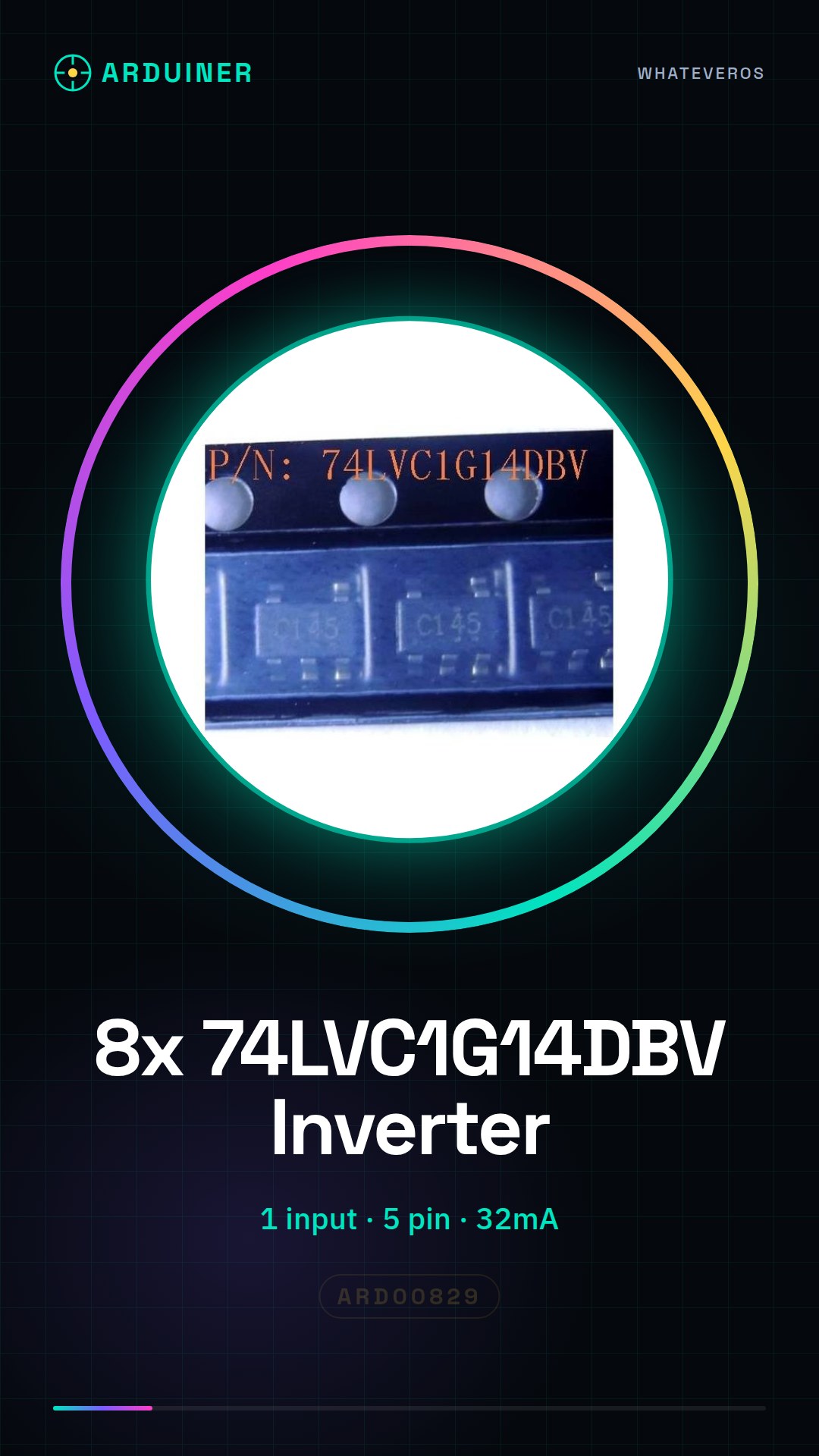
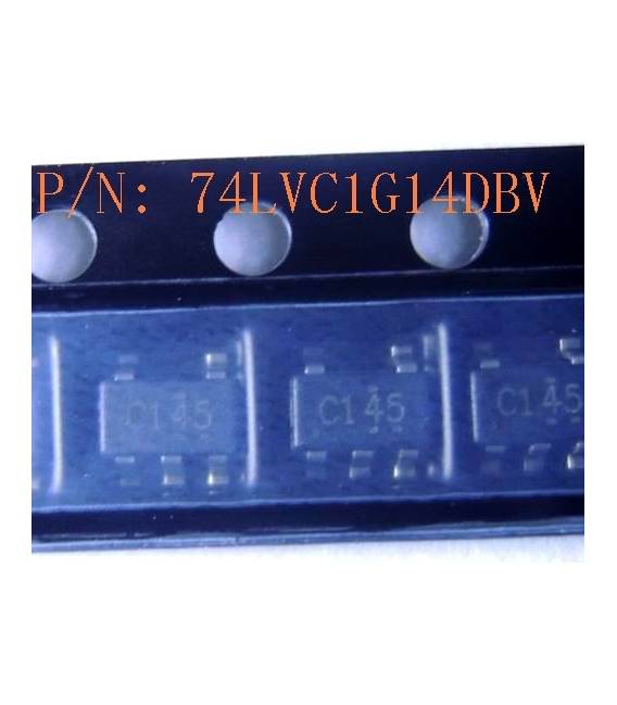
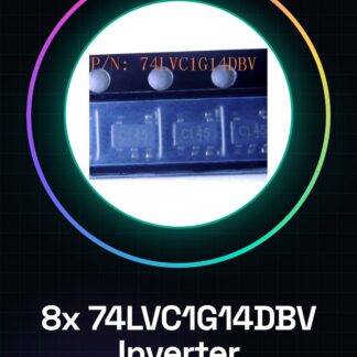
8PCS 74LVC1G14DBV IC Integrated Circuits
| Datasheets | SN74LVC1G14 |
|---|---|
| Product Photos | 74LVC Series (SOT-23) |
| Standard Package | 3.000 |
| Category | Integrated Circuits (IC) |
| Family | Logic – Gates and Inverters |
| Series | 74LVC |
| Logic Type | Inverter, Buffer |
| Number of Circuits | 1 |
| Number of Inputs | 1 |
| Features | Schmitt Trigger |
| Voltage – Supply | 1,65 V ~ 5,5 V |
| Current – Quiescent (Max) | |
| Current – Output high, low | 32mA, 32mA |
| Logic Level – Low | 0,39 V ~ 1,87 V |
| Logic Level – High | 1,16 V ~ 3,33 V |
| Propagation Delay Maximum @ V, Max CL | 5ns @ 5V, 50pF |
| Operating Temperature |
We have available the technical sheet of all components, should it not be present in the product download card, send us a message from the contact us module and we will publish as soon as possible on our site.
Tutorial: How to use 8 Pieces 74LVC1G14DBV IC Integrated Circuits
These ICs are useful for projects requiring a binary logic amplifier. Ideal for beginners and intermediates.
What you need
- 8 pieces 74LVC1G14DBV IC
- Multimeter
- Craft knife
- Test leads
Steps
- Check the component specifications on the datasheet.
- Prepare the test circuit on a protoboard.
- Connect the VCC to +5V.
- Connect the GND to the circuit ground.
- Connect the input (IN) to a logic signal.
- Measure the output (OUT) with the multimeter.
- Verify the logic amplification function.
- Test the short-circuit resistance.
Mini project
Build a simple logic inversion circuit with a button and an LED.
Common mistakes
- Connect the input directly to VCC.
- Omit the GND connection.
- Do not verify the amplification function.
- Ignore the short-circuit resistance test.
Recommended accessories
- Button
- LED
- Resistor
- Protoboard
Frequently asked questions
How can I verify the logic amplification function?
Measure the output with a high and low logic signal.
Which specifications should I check on the datasheet?
Check the operating voltage and short-circuit resistance.
Can I use these ICs for power circuits?
No, these ICs are designed for logic circuits.
Reviews
There are no reviews yet.