 EN
 IT Italiano
 ES Español
 FR Français
 DE Deutsch
Description
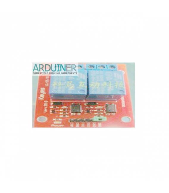
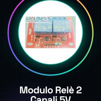
5V 2 channel relay module for PIC ARM AVR DSP
Relay contact capacity 250V10A. Relay output normally open, normally closed;
Low active. Relay signal input voltage range 5 V: 0-5 V;
System power supply VCC. Relay power JD-VCC. Default relay 5V. JD-VCC and VCC shorted.
Product description
This is a 5V 2-channel relay interface board, capable of controlling various devices and other equipment with high current. It can be directly controlled by a microcontroller (Arduino, 8051, AVR, PIC, DSP, ARM, ARM, MSP430, TTL logic).
1 . 2-channel 5V relay interface board, and each requires a driver current of 15-20mA
2 . Equipped with high current relay, AC250V 10A; DC30V 10A
Standard interface that can be directly controlled by the microcontroller (Arduino, 8051, AVR, PIC, DSP, ARM, ARM, MSP430, TTL logic)
4 . Relay output status indication
Technical sheets of all components are available, if not present in the product download card, send a message from the contact us module and we will publish as soon as possible on our website.
Tutorial: How to use 2 Channel 5V Relay Module
This 2-channel relay module is ideal for controlling electrical devices from a microcontroller like Arduino. It is suitable for both beginners and electronics experts.
What you need
- Arduino Uno or similar
- USB cable
- 5V power supply
Steps
- Connect the relay module to the Arduino using the GPIO connectors.
- Connect the power supply to the relay module (check the datasheet for specific pins).
- Write and upload an Arduino sketch that activates/deactivates the relay channels.
- Verify that the device connected to the relay turns on/off correctly.
Example code
// Definire i pin GPIO
const int relay1 = 2;
const int relay2 = 3;
void setup() {
pinMode(relay1, OUTPUT);
pinMode(relay2, OUTPUT);
digitalWrite(relay1, HIGH); // Disattiva il relè inizialmente
digitalWrite(relay2, HIGH);
}

void loop() {
digitalWrite(relay1, LOW); // Attiva il relè 1 per alcuni secondi
delay(5000);
digitalWrite(relay1, HIGH);
delay(5000);
digitalWrite(relay2, LOW); // Attiva il relè 2 per altri secondi
delay(5000);
digitalWrite(relay2, HIGH);
}
Mini project
Create an automatic control system for a lamp or fan using this relay module and a motion sensor. Configure the project so that the light turns on when something is detected and turns off after a few minutes.
Common mistakes
- Do not connect the correct voltage to the module.
- Set the Arduino GPIO pins to INPUT instead of OUTPUT.
- Omit the delay between relay states.
- Use a device that draws too much current for the relay.
Recommended accessories
- PIR Motion Sensor
- 12V Lamp
- Relay Shield
- LCD Module
Frequently asked questions
How can I control more devices?
Use a multiplexer module to map the Arduino GPIO pins to the relay channels.
What types of devices can the relay handle?
Devices that require a voltage below 250VAC/30VDC and a maximum current flow (check the datasheet).
Reviews
There are no reviews yet.