 EN
 IT Italiano
 ES Español
 FR Français
 DE Deutsch
Description
Technical Specifications
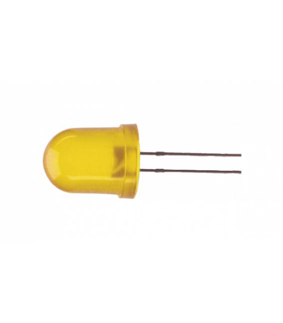
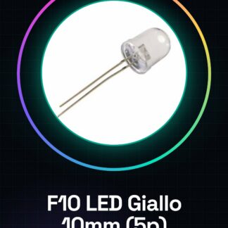
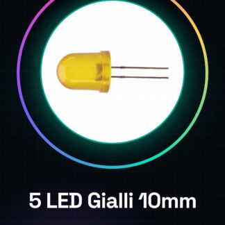
The yellow F10 LED diodes are electronic components used to indicate the status of a circuit or to illuminate it. They have a size of 10mm and are designed to be easily integrated into prototyping projects and laboratory applications.
The long pin of the diode represents the anode (positive), while the short pin represents the cathode (negative). The correct polarity of the diode is crucial for its proper functioning.
To use these diodes, they must be connected to a resistor and a power source, such as an Arduino Uno, to control their on and off states.
Key Specifications
| Parameter | Value |
| Model | F10 |
| Quantity | 5 |
| Color | Yellow |
| Dimensions | 10mm |
| Container | Pack of 5 pieces |
Installation and Usage
- Check the diode polarity: the long pin is the anode (positive), the short pin is the cathode (negative).
- Connect one end of the resistor to a digital pin of the Arduino and the other end to the long leg of the LED.
- Connect the other leg of the LED (short) to the GND of the Arduino using a jumper wire.
- Repeat steps 2-3 for each additional LED, using different digital pins and separate resistors.
- Open Arduino IDE and upload a sketch that turns the LEDs on and off in sequence or simultaneously.
Compatibility and Requirements
- Works with Arduino Uno and other prototyping systems.
- Requires resistors and jumper wires for connection.
- Can be used with variable resistors for testing and configuration.
- Suitable for laboratory projects and prototyping.
Limitations and Important Notes
- Cannot be used without a resistor to protect the diode.
- Not suitable for continuous lighting applications without a protective circuit.
- Be careful with polarity during connection.
- The operating voltage and maximum current must be verified in the product datasheet.
Troubleshooting
The LED does not light up.
Probable cause: Incorrect connection or insufficient resistance.
Solution: Check the polarity of the LED and the value of the resistor.
The LED glows dimly.
Probable cause: Resistance is too high.
Solution: Replace the resistor with one of a lower value.
The LED burns out.
Probable cause: Resistance is too low or incorrect connection.
Solution: Check the polarity of the LED and the value of the resistor.
The LED flickers irregularly.
Probable cause: Power supply issues or incorrect connections.
Solution: Check the stability of the power supply voltage and connections.
Use cases
Home security alarm system
Objective: To indicate the activation of an alarm.
What is needed: Arduino Uno, resistors, jumper wires.
Steps: 1) Connect the LEDs to the digital pins of the Arduino. 2) Program a sketch that turns on the LEDs in case of an alarm. 3) Test the alarm system.
Expected result: The alarm system indicates activation through the LEDs.
Lab project
Objective: Test the operation of a circuit.
What you need: Arduino Uno, resistors, jumper cables.
Steps: 1) Connect the LEDs to the digital pins of the Arduino. 2) Program a sketch that turns on the LEDs. 3) Test the circuit.
Expected result: The LEDs indicate the state of the circuit.
Light control system
Objective: Adjust the lighting.
What you need: Arduino Uno, resistors, jumper cables, variable resistor.
Steps: 1) Connect the LEDs to the digital pins of the Arduino. 2) Program a sketch that regulates the intensity of the LEDs. 3) Test the light control system.
Expected result: The system adjusts the lighting through the LEDs.
School Project
Objective: Demonstrate the operation of an LED.
What is needed: Arduino Uno, resistors, jumper wires.
Steps: 1) Connect the LEDs to the digital pins of the Arduino. 2) Program a sketch that turns the LEDs on and off. 3) Show the operation of the LED.
Expected result: The LEDs indicate the state of the circuit.
Temperature Control System
Objective: Indicate the temperature.
What is needed: Arduino Uno, resistors, jumper wires, temperature sensor.
Steps: 1) Connect the LEDs to the digital pins of the Arduino. 2) Program a sketch that turns the LEDs on based on the temperature. 3) Test the temperature control system.
Expected result: The LEDs indicate the temperature.
Humidity Control System
Objective: Indicate the humidity.
What is needed: Arduino Uno, resistors, jumper wires, humidity sensor.
Steps: 1) Connect the LEDs to the digital pins of the Arduino. 2) Program a sketch that turns on the LEDs based on humidity. 3) Test the humidity control system.
Expected result: The LEDs indicate humidity.
Pressure control system
Objective: Indicate pressure.
What is needed: Arduino Uno, resistors, jumper cables, pressure sensor.
Steps: 1) Connect the LEDs to the digital pins of the Arduino. 2) Program a sketch that turns on the LEDs based on pressure. 3) Test the pressure control system.
Expected result: The LEDs indicate pressure.
Lighting control system
Objective: Regulate lighting.
What is needed: Arduino Uno, resistors, jumper cables, light sensor.
Steps: 1) Connect the LEDs to the digital pins of the Arduino. 2) Program a sketch that turns on the LEDs based on light. 3) Test the lighting control system.
Expected result: The LEDs adjust the lighting.
In the package
- 5 pieces of yellow LED diodes F10
Complete the project
- 5 Pieces F10 Yellow LED Diode 10mm Clear Lens: To use different colors of LEDs in a project.
Technical FAQ
What is the value of the resistor to use?
The value of the resistor depends on the supply voltage and the LED operating voltage. Check the product datasheet to determine the correct value.
Why doesn’t the LED light up?
Check the polarity of the LED and the value of the resistor. Also check the stability of the supply voltage.
What is the operating voltage of the LED?
The operating voltage of the LED is specified in the product datasheet.
What is the maximum current of the LED?
The maximum current of the LED is specified in the product datasheet.
Tutorial: How to use Yellow LED Diode F10
Yellow F10 LEDs are ideal for indicating the state of a circuit or for illuminating it. They are perfect for both beginners and more experienced makers.
What you need
- Arduino Uno
- 5 resistors of 330 ohms
- 5 pieces of jumper wire
Steps
- Check the polarity of the LED: the longer leg is the anode (positive).
- Connect one end of the resistor to a digital pin of the Arduino and the other end to the longer leg of the LED.
- Connect the other leg of the LED (shorter) to the GND of the Arduino using a jumper wire.
- Repeat steps 2-3 for each other LED, using different digital pins and separate resistors.
- Open Arduino IDE and upload a sketch that turns the LEDs on and off in sequence or simultaneously.
- Check the operating voltage on the LED datasheet and adjust the value of the resistor if necessary.
Example code
void setup() {
  pinMode(13, OUTPUT);
pinMode(12, OUTPUT);
pinMode(11, OUTPUT);
pinMode(10, OUTPUT);
pinMode(9, OUTPUT);
}

void loop() {
analogWrite(13, 255);
delay(500);
analogWrite(12, 255);
delay(500);
analogWrite(11, 255);
delay(500);
analogWrite(10, 255);
delay(500);
analogWrite(9, 255);
delay(500);
}
Mini project
Create a simple blinker clock with five yellow LEDs that blink in sequence.
Common mistakes
- Connect the short leg of the LED to the positive
- Using a resistor that is too small or too large
- Not checking the polarity of the LED
Recommended accessories
- Variable resistors
- Breadboard
- Arduino Uno R3
- Universal jumper cable kit
Frequently asked questions
What is the ideal value of the resistor?
Check the datasheet of the LED for the operating voltage and calculate the correct value.
Can I connect multiple LEDs in series or in parallel?
Yes, but make sure the values of the resistors are appropriate to prevent damage to the LEDs.
Reviews
There are no reviews yet.