 EN
 IT Italiano
 ES Español
 FR Français
 DE Deutsch
Description
Technical Specifications
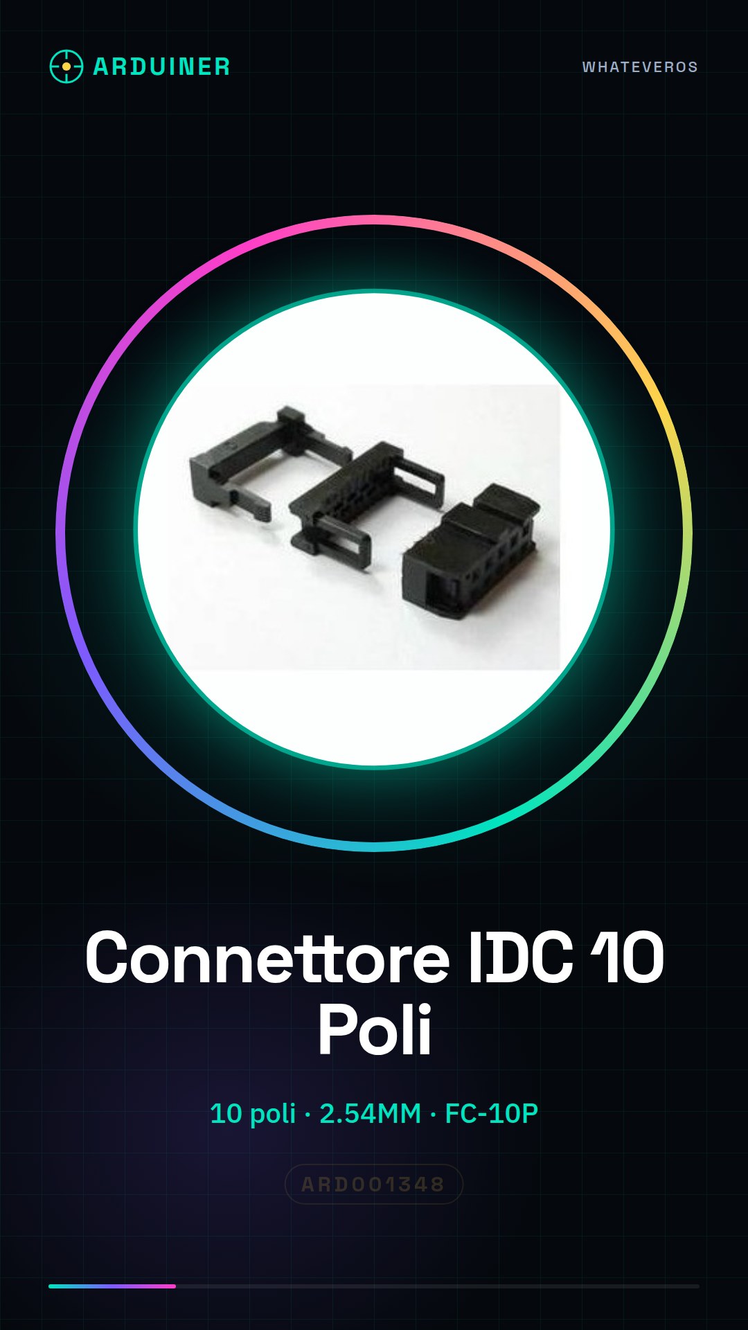
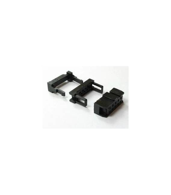
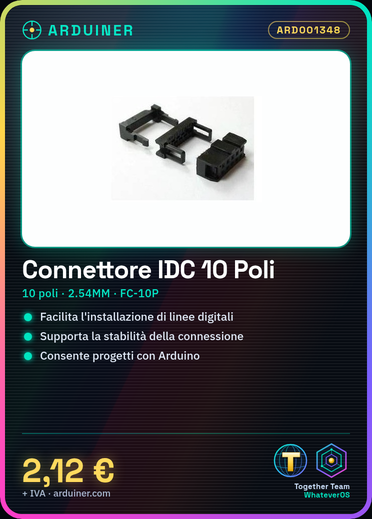
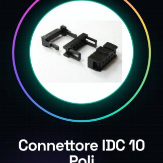
The 10-pin IDC (Inter-Integrated Circuit) connector is a component used for connecting flat cables to boards or circuits. This type of connector facilitates the installation of digital and analog signal lines, ensuring a stable and secure connection. The 10-pin IDC connector has a pitch of 2.54mm and features a cavity layout for the entry of flat cable wires.
The 10-pin IDC connector is equipped with female cavities, which accommodate the flat cable wires, ensuring a stable electrical connection. Its application is widely used in electronics projects, prototyping, and circuit testing.
For the installation of the 10-pin IDC connector, a wire stripper tool is required to separate the wires from the flat cable and insert them correctly into the connector cavities. The stability of the connection is ensured by the pressure applied to the opposite side of the connector.
Key Specifications
| Parameter | Value |
| Model | FC-10P |
| Number of Pins | 10 |
| Pitch | 2.54mm |
| Type | Female Socket |
| Dimensions | N/D (see manufacturer’s technical sheet) |
| Container | N/D (see manufacturer’s technical sheet) |
Installation and Usage
- Ensure that the number of pins on the IDC connector matches those of the flat cable (10 pins in this case).
- Use a wire stripper to separate the wires from the flat cable to the necessary length.
- Insert the flat cable into the IDC connector, ensuring that each individual wire is properly seated in one of the 10 cavities of the connector.
- Gently press on the opposite side of the connector to secure the wires inside.
- Connect the 10-pin IDC connector to a circuit or board using the side tabs as mounting points.
Compatibility and Requirements
- The 10-pin IDC connector is compatible with Arduino and other electronic prototyping systems.
- A 10-pin flat cable is required for installation.
- For use with Arduino, an appropriate flat cable and a compatible 10-pin IDC connector are necessary.
Limitations and Important Notes
- The 10-pin IDC connector is not designed for low-level or low-voltage connections.
- It is important to verify that the flat cable is compatible with the connector before installation.
- The pressure applied to the opposite side of the connector is crucial for ensuring a stable connection.
- It is recommended to consult the manufacturer’s technical documentation for further information.
Troubleshooting
Short circuit during installation
Probable cause: Incorrect insertion of wires into the connector
Solution: Verify the correct wire placement and repeat the installation.
Unstable connection
Probable cause: Not pressing the opposite side of the connector to secure the wires
Solution: Apply pressure to the opposite side of the connector to ensure a stable connection.
Weak or absent signal
Probable cause: Using a ribbon cable with a different number of poles than the IDC connector
Solution: Use a ribbon cable compatible with a 10-pin IDC connector.
Unstable connection
Probable cause: Incorrect insertion of wires into the connector
Solution: Check the correct arrangement of the wires and repeat the installation.
Use cases
Prototype lab
Objective: Connect a flat cable to a board
Needed: 10-pin IDC connector
Steps: 1) Check the compatibility of the flat cable 2) Separate the wires of the flat cable 3) Insert the wires into the IDC connector 4) Secure the wires by applying pressure on the opposite side of the connector 5) Connect the connector to a board
Expected result: Stable connection between the flat cable and the board.
Home automation project
Objective: Connect sensors to a control circuit
Needed: 10-pin IDC connector
Steps: 1) Verify the compatibility of the flat cable 2) Separate the wires of the flat cable 3) Insert the wires into the IDC connector 4) Secure the wires by applying pressure on the opposite side of the connector 5) Connect the connector to a control circuit
Expected result: Stable connection between the sensors and the control circuit.
Electronic circuit testing
Objective: Connect a flat cable to an oscilloscope
Required: 10-pin IDC connector
Steps: 1) Verify the compatibility of the flat cable 2) Separate the wires of the flat cable 3) Insert the wires into the IDC connector 4) Secure the wires by applying pressure on the opposite side of the connector 5) Connect the connector to an oscilloscope
Expected result: Stable connection between the flat cable and the oscilloscope.
DIY electronics project
Objective: Connect a flat cable to a prototype circuit
Required: 10-pin IDC connector
Steps: 1) Verify the compatibility of the flat cable 2) Separate the wires of the flat cable 3) Insert the wires into the IDC connector 4) Secure the wires by applying pressure on the opposite side of the connector 5) Connect the connector to a prototype circuit
Expected result: Stable connection between the flat cable and the prototype circuit.
Maintenance of electronic equipment
Objective: Replace a damaged flat cable
What is needed: 10-pin IDC connector
Steps: 1) Verify the compatibility of the flat cable 2) Separate the wires of the flat cable 3) Insert the wires into the IDC connector 4) Secure the wires by applying pressure on the opposite side of the connector 5) Connect the connector to the circuit by replacing the damaged flat cable
Expected result: Replacement of the flat cable with a stable connection.
Repair of electronic circuits
Objective: Reconnect a flat cable to a damaged circuit
What is needed: 10-pin IDC connector
Steps: 1) Verify the compatibility of the flat cable 2) Separate the wires of the flat cable 3) Insert the wires into the IDC connector 4) Secure the wires by applying pressure on the opposite side of the connector 5) Connect the connector to the repaired circuit
Expected result: Stable connection between the flat cable and the repaired circuit.
Industrial automation project
Objective: Connect a flat cable to an industrial control system
What is needed: 10-pin IDC connector
Steps: 1) Verify the compatibility of the flat cable 2) Separate the wires of the flat cable 3) Insert the wires into the IDC connector 4) Secure the wires by applying pressure on the opposite side of the connector 5) Connect the connector to an industrial control system
Expected Result: Stable connection between the flat cable and the industrial control system.
Electronic hobby project
Objective: Connect a flat cable to a prototype circuit
Required: 10-pin IDC connector
Steps: 1) Check the compatibility of the flat cable 2) Separate the wires of the flat cable 3) Insert the wires into the IDC connector 4) Secure the wires by applying pressure on the opposite side of the connector 5) Connect the connector to a prototype circuit
Expected Result: Stable connection between the flat cable and the prototype circuit.
In the package
- 4 Pieces IDC Flat Cable Connector 10 Pin 2.54MM Pitch Socket Female FC-10P
Complete the project
- 4 Pieces IDC Flat Cable Connector 16 Pin 2.54MM Pitch Socket Female FC-16P: For connecting flat cables with different pin counts.
- 4 Pieces DC3-10P 2.54MM Pitch 10 Pole Header Socket for Flat Ribbon Cable JTAG: For the installation of flat cables with a higher number of poles.
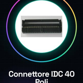
- 2 Pieces IDC Flat Cable Connector 40 Pole 2.54MM Pitch Socket Female FC-40P: For connecting flat cables with a lower number of poles.
Technical FAQs
Can the IDC connector be used with other types of cable?
Check the connector datasheet to ensure the pitch and pole configuration match those of the cable.
How is the stability of the IDC connector connection verified?
Apply pressure on the opposite side of the connector to secure the wires inside.
What are the limitations of using a 10 pole IDC connector?
The 10 pole IDC connector is not designed for low-level or low-voltage connections and requires a compatible flat cable.
What are the steps to resolve a short circuit during the installation of an IDC connector?
Check the correct wire placement and repeat the installation.
Tutorial: How to Use 10-Pin IDC Connector
The 10-pin IDC (Inter-Integrated Circuit) connector is an essential component for electronic projects requiring the connection between flat cables and boards or other circuits. Ideal for beginner and intermediate makers, this connector simplifies the installation of digital signal lines.
What you need
- 10-pin flat cable
- cable splitter tool
Steps
- Verify that the number of pins on the IDC connector matches those of your flat cable (10 pins in this case).
- Use a cable splitter tool to separate the wires from the flat cable to the required length.
- Insert the flat cable into the IDC connector, ensuring that each individual wire is properly seated in one of the 10 slots of the connector.
- Gently press on the opposite side of the connector to secure the wires inside. Check the stability of the connection.
- Connect the IDC connector to a circuit or board using the side tabs as anchoring points.
Mini project
Create a simple interface with Arduino that reads signals from a flat cable through a 10-pin IDC connector. Connect various sensors to the cable and display the data on the serial monitor.
Common mistakes
- Insert the wires into the connector incorrectly, causing short circuits or signal loss.
- Do not press the opposite side of the connector to secure the wires, making the connection unstable.
- Use a flat cable with a different number of pins than the IDC connector.
Recommended accessories
- 10-pin flat cable
- cable splitter tool
- Arduino board
- various sensors
Frequently asked questions
Can the IDC connector be used with other types of cable?
Check the connector datasheet to ensure that the pitch and pin configuration match those of your flat cable.
How can I remove the wires from the IDC connector if I made a mistake?
Use a prying tool to gently lift the side tabs and you will remove the flat cable.
Reviews
There are no reviews yet.