 EN
 IT Italiano
 ES Español
 FR Français
 DE Deutsch
Description
Technical Description
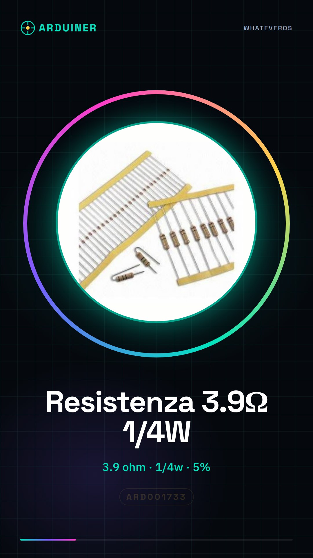
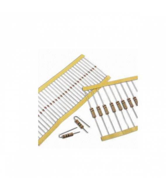
The 3.9 ohm resistor is a fundamental component for limiting the flow of current in an electronic circuit. This type of resistor is used to protect electronic circuits, such as those based on Arduino, from excessive currents that could damage them. The resistor limits the current so that the device does not exceed its heat dissipation capacity, ensuring safe and stable operation of the circuit.
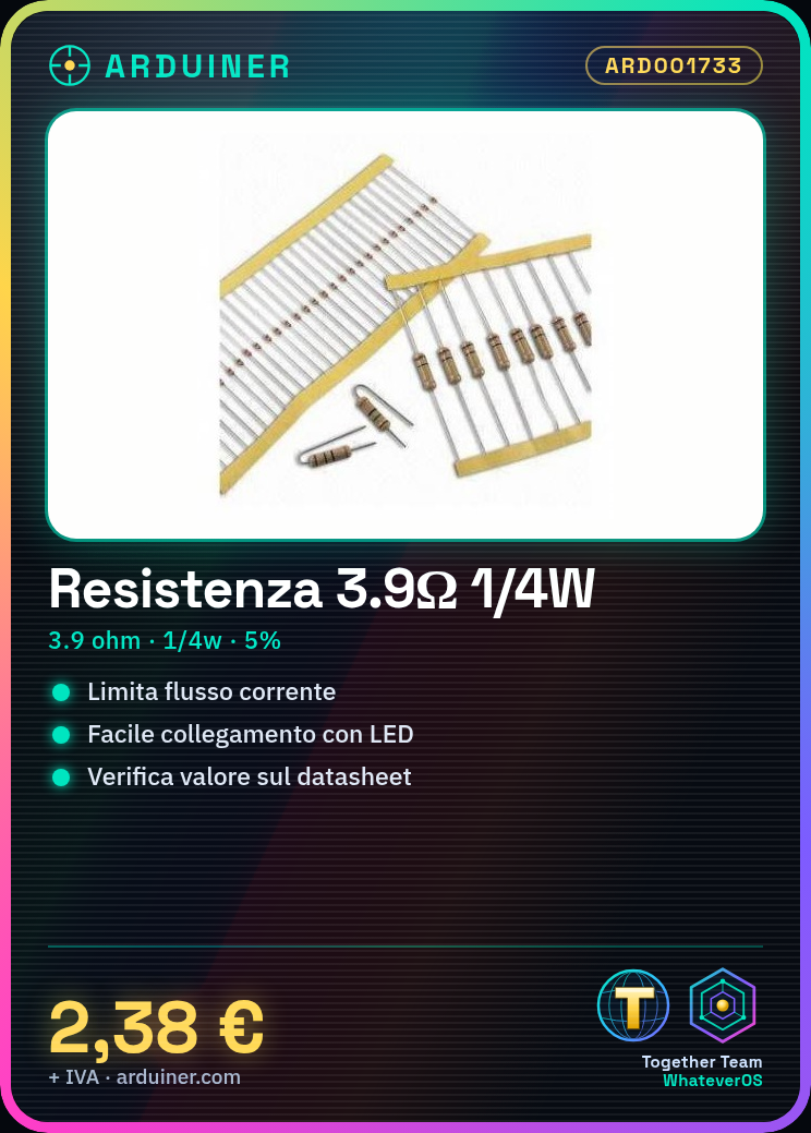
The 3.9 ohm resistor can be used in various electronic projects, such as limiting the current through an LED or creating a voltage divider circuit. Its specific resistance and its maximum power dissipation (1/4 watt) are crucial for determining its applicability in a specific circuit.
Key Specifications
| Parameter | Value |
| Model | 3.9 ohm Resistor |
| Quantity | 50 pieces |
| Resistive Value | 3.9 ohm |
| Tolerance | 5% |
| Maximum Power | 1/4 watt |
| Dimensions | N/D (see manufacturer’s datasheet) |
| Container | N/D (see manufacturer’s datasheet) |
Installation and Usage
- Check the resistance value (3.9 ohm) on the datasheet.
- Connect the resistor between an Arduino output pin and an LED.
- Use the Arduino IDE software to upload a sketch that turns the LED with the connected resistor on and off.
- Verify that the resistor is correctly connected and that the circuit functions as expected.
- Perform a functionality test to confirm that the resistor correctly limits the current.
Compatibility and Requirements
- The 3.9 ohm resistor is compatible with Arduino Uno and other microcontroller-based systems.
- A programming software like Arduino IDE is required to upload the necessary sketches.
- Standard electronic connectors can be used to connect the resistor to the circuit.
Limitations and Important Notes
- The resistor cannot handle power greater than 1/4 watt.
- Do not use the resistor in reverse to the current flow.
- Ensure that the resistor is suitable for the circuit in which it is used.
- The resistor cannot be used in circuits requiring heat dissipation greater than its capacity.
Troubleshooting
The LED does not light up.
Probable cause: The resistor may be connected in reverse to the current flow.
Solution: Check the resistor connection and invert its position if necessary.
The LED glows dimly.
Probable cause: The resistor may have a value too high for the circuit.
Solution: Check the resistor value and replace it with one of a lower value if necessary.
The circuit does not respond.
Probable cause: The resistor may not be correctly connected to the circuit.
Solution: Check all connections and ensure that the resistor is properly positioned.
The circuit overheats.
Probable cause: The resistor may not be able to dissipate the heat generated.
Solution: Verify that the resistor is suitable for the circuit’s power and consider using a resistor with a higher heat dissipation capacity.
Use cases
Light sensor for home
Objective: Create a light control system.
What you need: Arduino Uno, 3.9 ohm resistor, photodiode, electronic connectors.
Steps: 1) Connect the photodiode to the circuit. 2) Use the 3.9 ohm resistor to limit the photodiode’s current. 3) Program the Arduino to measure light intensity. 4) Test the light control system.
Expected result: The system correctly measures the brightness and adjusts the lighting brightness.
Step counter for hobby
Objective: Create a step counter.
What you need: Arduino Uno, 3.9 ohm resistor, pressure sensors, electronic connectors.
Steps: 1) Connect the pressure sensors to the circuit. 2) Use the 3.9 ohm resistor to limit the current of the sensors. 3) Program the Arduino to count the steps. 4) Test the step counter.
Expected result: The step counter correctly records the steps.
School alarm system
Objective: Create an alarm system.
What you need: Arduino Uno, 3.9 ohm resistor, motion sensors, electronic connectors.
Steps: 1) Connect the motion sensors to the circuit. 2) Use the 3.9 ohm resistor to limit the current of the sensors. 3) Program the Arduino to activate the alarm. 4) Test the alarm system.
Expected result: The alarm system correctly activates the alarm.
Lab thermostat control system
Objective: Create a thermostat control system.
What you need: Arduino Uno, 3.9 ohm resistor, temperature sensors, electronic connectors.
Steps: 1) Connect the temperature sensors to the circuit. 2) Use the 3.9 ohm resistor to limit the current of the sensors. 3) Program the Arduino to regulate the temperature. 4) Test the thermostat control system.
Expected result: The thermostat control system correctly regulates the temperature.
Temperature control system for maintenance
Objective: Create a temperature control system.
What’s needed: Arduino Uno, 3.9 ohm resistor, temperature sensors, electronic connectors.
Steps: 1) Connect the temperature sensors to the circuit. 2) Use the 3.9 ohm resistor to limit the current of the sensors. 3) Program the Arduino to monitor the temperature. 4) Test the temperature control system.
Expected result: The temperature control system monitors the temperature correctly.
Temperature control system for repair
Objective: Create a temperature control system.
What’s needed: Arduino Uno, 3.9 ohm resistor, temperature sensors, electronic connectors.
Steps: 1) Connect the temperature sensors to the circuit. 2) Use the 3.9 ohm resistor to limit the current of the sensors. 3) Program the Arduino to regulate the temperature. 4) Test the temperature control system.
Expected result: The temperature control system regulates the temperature correctly.
Temperature control system for testing
Objective: Create a temperature control system.
What’s needed: Arduino Uno, 3.9 ohm resistor, temperature sensors, electronic connectors.
Steps: 1) Connect the temperature sensors to the circuit. 2) Use the 3.9 ohm resistor to limit the current of the sensors. 3) Program the Arduino to monitor the temperature. 4) Test the temperature control system.
Expected result: The temperature control system monitors the temperature correctly.
Home Automation Temperature Control System
Objective: Create a temperature control system.
What’s needed: Arduino Uno, 3.9 ohm resistor, temperature sensors, electronic connectors.
Steps: 1) Connect the temperature sensors to the circuit. 2) Use the 3.9 ohm resistor to limit the current of the sensors. 3) Program the Arduino to regulate the temperature. 4) Test the temperature control system.
Expected result: The temperature control system correctly regulates the temperature.
In the package
- 50 pieces
Complete the project
- 50 Pieces Resistor 1000 ohm 1k ohm 1/4w 1/4 w 5%: Used to limit the current in circuits with resistors of different values.
- 50 Pieces Resistor, 10000 ohm, 10k, ohm 1/4w 1/4 w 5%, Arduino Compatible Resistors: Used to limit the current in circuits with resistors of different values.
- 50 Pieces 100 ohm 1/4w 5% resistor: It is used to limit the current in circuits with resistors of different values.
- 50 Pieces 220 ohm 1/4w 1/4 w 5% resistor: It is used to limit the current in circuits with resistors of different values.
- 50 Pieces 4.7K ohm 4700 ohm 1/4w 1/4 w 5% resistor: It is used to limit the current in circuits with resistors of different values.
Technical FAQs
What is the maximum power it can handle?
Check the datasheet, usually 1/4 watt.
Can I use a resistor of a different value?
Yes, but make sure your circuit is designed for that value.
What are the heat dissipation limits?
Heat dissipation is limited to the maximum power dissipation (1/4 watt).
What are the steps to connect the resistor?
Check the resistance value on the datasheet, connect the resistor between an Arduino output pin and an LED, use the Arduino IDE software to upload a sketch that turns the LED on and off with the connected resistor.
Tutorial: How to Use 3.9 Ohm Resistor
The resistor is a fundamental component for limiting the flow of current in an electronic circuit. This tutorial will guide you on how to use the 3.9 ohm resistor in your Arduino project.
What you need
- Arduino Uno
- Connectors
- Circuit Board Printing
Steps
- Check the resistance value (3.9 ohm) on the datasheet.
- Connect the resistor between an Arduino output pin and an LED.
- Use the Arduino IDE software to upload a sketch that turns the LED on and off with the connected resistor.
Example code
void setup() {
  pinMode(13, OUTPUT);
}

void loop() {
  digitalWrite(13, HIGH);
  delay(1000);
  digitalWrite(13, LOW);
  delay(1000);
}
Mini project
Create a simple blink circuit with a resistor and an LED. Connect the resistor between the Arduino output pin (e.g., pin 13) and the anode of the LED, connecting the cathode to GND.
Common mistakes
- Connect the resistor in reverse.
- Do not verify the resistor value on the datasheet.
- Use a resistor with insufficient power rating for your application.
Recommended accessories
- Arduino Uno
- LEDs in various colors
- Electronic connections
Frequently asked questions
What is the maximum power it can handle?
Check the datasheet, usually 1/4w.
Can I use a resistor of a different value?
Yes, but make sure your circuit is designed for that value.
Reviews
There are no reviews yet.