 EN
 IT Italiano
 ES Español
 FR Français
 DE Deutsch
Description
Technical Description
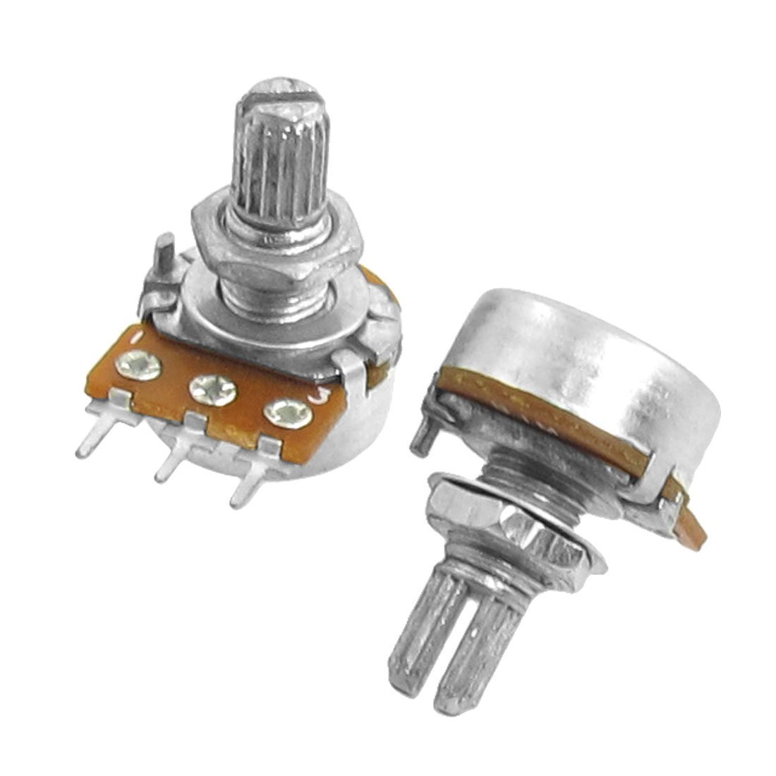
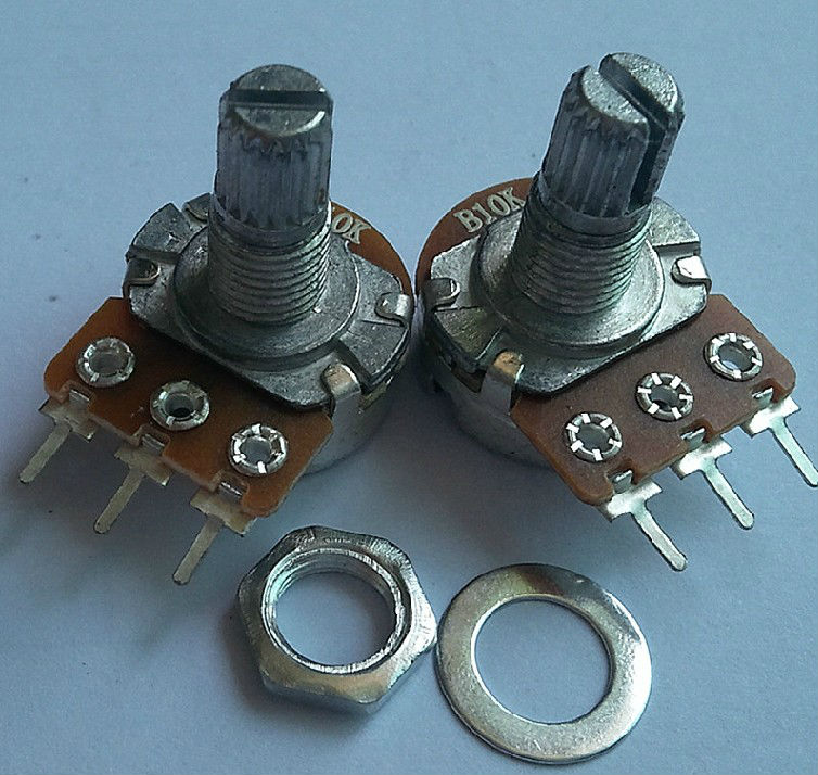
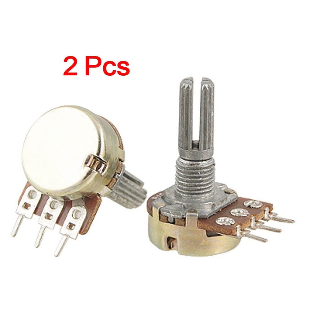
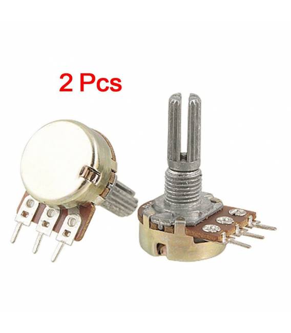
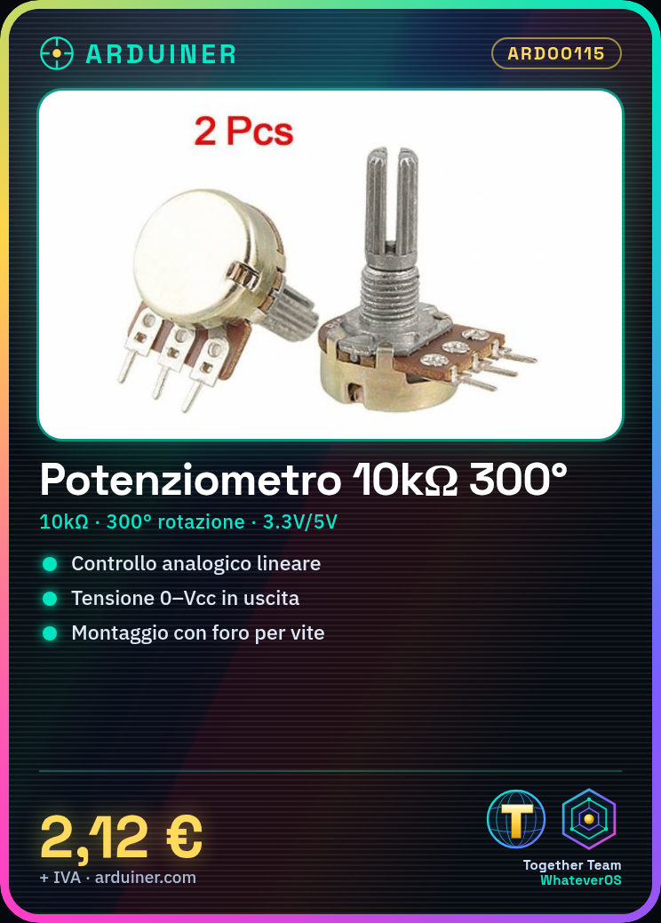
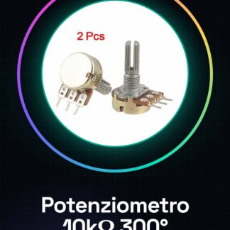
The WH148-K2-4 rotary potentiometer is an electronic component with a resistive value of 10 kΩ and a total rotation angle of 300 degrees. This potentiometer provides an analog voltage output proportional to the rotation angle, varying linearly from 0V to Vcc (typically 5V). It is designed to be used in various electronic systems, such as Arduino, ESP32, ESP8266, Raspberry Pi, and other microcontrollers.
The WH148-K2-4 potentiometer has three pins: VCC, GND, and OUT. The VCC pin is connected to the power supply voltage, GND to ground level, and OUT to the analog output. The rotation of the potentiometer changes the resistance between the wiper and the terminals, generating an analog signal that can be read by microcontrollers to control variables such as volume or brightness.
To use the WH148-K2-4 potentiometer, it is necessary to connect it correctly to the power supply and output pins of the chosen microcontroller. Ensure to respect the specified power supply voltage to avoid damaging the component.
Key Specifications
| Parameter | Value |
| Model | WH148-K2-4 |
| Type | Rotary Potentiometer |
| Resistive Value | 10 kΩ |
| Variation Type | Linear (Type B) |
| Total Rotation Angle | 300° |
| Operating Voltage | 3.3V / 5V |
| Output | Analog Voltage (0V – Vcc) |
| Number of Pins | 3 (VCC, GND, OUT) |
| Mounting | Threaded hole for screw on PCB |
Installation and Usage
- Connect the VCC pin of the potentiometer to the power supply pin of the microcontroller (5V for Arduino).
- Connect the GND pin of the potentiometer to the ground pin of the microcontroller.
- Connect the OUT pin of the potentiometer to an analog input pin of the microcontroller (for example A0 for Arduino).
- Insert the example code provided into the microcontroller to read the analog values from the potentiometer.
- Run the code and verify that the analog output varies correctly with the rotation of the potentiometer.
Compatibility and Requirements
- The WH148-K2-4 potentiometer is compatible with Arduino, ESP32, ESP8266, Raspberry Pi, and other microcontrollers.
- A microcontroller with at least one analog input pin is required to use this potentiometer.
- To use the potentiometer, a microcontroller programming software like Arduino IDE is required.
Limitations and Important Notes
- The WH148-K2-4 potentiometer is not designed for high-frequency or high-voltage applications.
- Rotating the potentiometer beyond the 300-degree limit may damage the component.
- Ensure to adhere to the specified power supply voltage to prevent damage to the potentiometer.
Troubleshooting
The analog signal does not change with the rotation of the potentiometer.
Probable cause: Incorrect pin connections of the potentiometer.
Solution: Check the connections and recalibrate the microcontroller.
The analog signal is constant and does not vary.
Probable cause: The potentiometer may be jammed or damaged.
Solution: Inspect the potentiometer for any damage and replace it if necessary.
The analog signal varies incorrectly.
Probable cause: Power supply voltage is not compliant.
Solution: Check the power supply voltage and ensure it is in accordance with the potentiometer specifications.
The analog signal is disturbed.
Probable cause: Electronic interference.
Solution: Use an electronic filter to reduce interference.
Use cases
LED brightness control
Objective: Adjust the brightness of an LED based on the rotation of the potentiometer.
What is needed: LED, resistor, potentiometer WH148-K2-4, microcontroller.
Steps: 1) Connect the potentiometer to the power supply and output pins of the microcontroller. 2) Connect the LED to the resistor and the microcontroller. 3) Write the code to adjust the LED brightness based on the potentiometer output. 4) Run the code and adjust the LED brightness with the potentiometer.
Expected Result: The brightness of the LED varies proportionally to the rotation of the potentiometer.
Volume Control of a Speaker
Objective: Adjust the volume of a speaker based on the rotation of the potentiometer.
What’s needed: Speaker, amplifier, potentiometer WH148-K2-4, microcontroller.
Steps: 1) Connect the potentiometer to the power and output pins of the microcontroller. 2) Connect the speaker to the amplifier and the microcontroller. 3) Write the code to adjust the volume of the speaker based on the output of the potentiometer. 4) Run the code and adjust the volume of the speaker with the potentiometer.
Expected Result: The volume of the speaker varies proportionally to the rotation of the potentiometer.
Temperature Control of a Heating System
Objective: Adjust the temperature of a heating system based on the rotation of a potentiometer.
What’s needed: Thermistor, WH148-K2-4 potentiometer, microcontroller.
Steps: 1) Connect the potentiometer to the power and output pins of the microcontroller. 2) Connect the thermistor to the microcontroller. 3) Write the code to adjust the heating system’s temperature based on the potentiometer’s output. 4) Run the code and adjust the heating system’s temperature with the potentiometer.
Expected result: The temperature of the heating system varies proportionally to the rotation of the potentiometer.
Arm regulation of a robot
Objective: Adjust the angle of a robot’s arm based on the rotation of a potentiometer.
What’s needed: Servo motor, WH148-K2-4 potentiometer, microcontroller.
Steps: 1) Connect the potentiometer to the power and output pins of the microcontroller. 2) Connect the servo motor to the microcontroller. 3) Write the code to adjust the angle of the robot arm based on the potentiometer output. 4) Run the code and adjust the angle of the robot arm with the potentiometer.
Expected result: The angle of the robot arm varies proportionally to the rotation of the potentiometer.
Contrast adjustment of an LCD display
Objective: Adjust the contrast of an LCD display based on the rotation of the potentiometer.
What’s needed: LCD display, WH148-K2-4 potentiometer, microcontroller.
Steps: 1) Connect the potentiometer to the power and output pins of the microcontroller. 2) Connect the LCD display to the microcontroller. 3) Write the code to adjust the contrast of the LCD display based on the potentiometer output. 4) Run the code and adjust the contrast of the LCD display with the potentiometer.
Expected result: The contrast of the LCD display varies proportionally to the rotation of the potentiometer.
Audio system volume adjustment
Objective: Adjust the volume of an audio system based on the rotation of the potentiometer.
What’s needed: Audio amplifier, WH148-K2-4 potentiometer, microcontroller.
Steps: 1) Connect the potentiometer to the power and output pins of the microcontroller. 2) Connect the audio amplifier to the microcontroller. 3) Write the code to adjust the system audio volume based on the potentiometer output. 4) Run the code and adjust the system audio volume with the potentiometer.
Expected result: The system audio volume varies proportionally to the rotation of the potentiometer.
Speed regulation of a motor
What is needed: Motor, WH148-K2-4 potentiometer, microcontroller.
Steps: 1) Connect the potentiometer to the power and output pins of the microcontroller. 2) Connect the motor to the microcontroller. 3) Write the code to adjust the motor speed based on the potentiometer output. 4) Run the code and adjust the motor speed with the potentiometer.
Expected Result: The motor speed varies proportionally to the potentiometer rotation.
Voltage Regulation of a Circuit
What’s needed: Voltage regulator, WH148-K2-4 potentiometer, microcontroller.
Steps: 1) Connect the potentiometer to the power and output pins of the microcontroller. 2) Connect the voltage regulator to the microcontroller. 3) Write the code to regulate the circuit voltage based on the potentiometer output. 4) Run the code and adjust the circuit voltage with the potentiometer.
Expected Result: The circuit voltage varies proportionally to the potentiometer rotation.
In the package
- 2 pieces WH148-K2-4
Complete the project
- 2 pieces 3362p potentiometer trimmer 10k 10k: To adjust the volume of an audio system or the contrast of an LCD display.
- Precision multi-turn linear potentiometer 10kohm 3590S-2-103L 3590S 10K: To add temperature or light control to the system.
- Slide potentiometer linear fader 10k 5v with dual output for Arduino: To add speed control to a motor or angle control to a robot arm.
- Trimmer Potentiometer 10K with knob for Arduino: To add voltage control to a circuit or angle control to a servo motor.
Technical FAQs
How do I connect the WH148-K2-4 potentiometer to a microcontroller?
Connect the VCC pin of the potentiometer to the power supply pin of the microcontroller, the GND pin to the ground pin of the microcontroller, and the OUT pin to an analog input pin of the microcontroller.
What are the rotation limits of the WH148-K2-4 potentiometer?
The WH148-K2-4 potentiometer has a total rotation angle of 300 degrees.
What are the acceptable supply voltages for the WH148-K2-4 potentiometer?
The WH148-K2-4 potentiometer accepts supply voltages of 3.3V and 5V.
What are the symptoms of a damaged potentiometer?
A damaged potentiometer may show a constant analog signal or erroneous variations of the analog signal.
Tutorial: How to use Rotating Potentiometer WH148-K2-4 10K 300°
The WH148-K2-4 10K 300° rotary potentiometer is an electronic component that allows continuous adjustment of resistance value. It is ideal for beginners and makers who want to control variables such as sound volume or LED brightness.
What you need
- Arduino Uno or compatible
- Head connectors
Steps
- Connecting the potentiometer to the circuit: the left end to ground (GND), the right end to the voltage reference (VCC), and the center to the Arduino input pin.
- Write an Arduino sketch that reads the value of the potentiometer from an input pin.
- Display the potentiometer value on the Arduino serial monitor.
Example code
int potPin = A0;
int potVal = 0;
void setup() {
  Serial.begin(9600);
}
void loop() {
  potVal = analogRead(potPin);
  Serial.println(potVal);
}
Mini project
Create a dimmer for an LED, adjusting the brightness with the rotary potentiometer. Connect an LED to an output pin of the Arduino and use the potentiometer value to adjust the light intensity.
Common mistakes
- Connect the potentiometer to an output pin instead of an analog input pin.
- Do not check the polarity of the connectors.
- Use a resistance value that is not compatible with the circuit.
Recommended accessories
- Arduino Uno
- LED
- Resistors
Frequently asked questions
What is the resistance of the potentiometer?
Check the datasheet.
How can I connect multiple potentiometers?
Connect each end of the potentiometer to ground (GND) and the voltage reference (VCC), and the center to different input pins of the Arduino.
Reviews
There are no reviews yet.