 EN
 IT Italiano
 ES Español
 FR Français
 DE Deutsch

Description
What it is
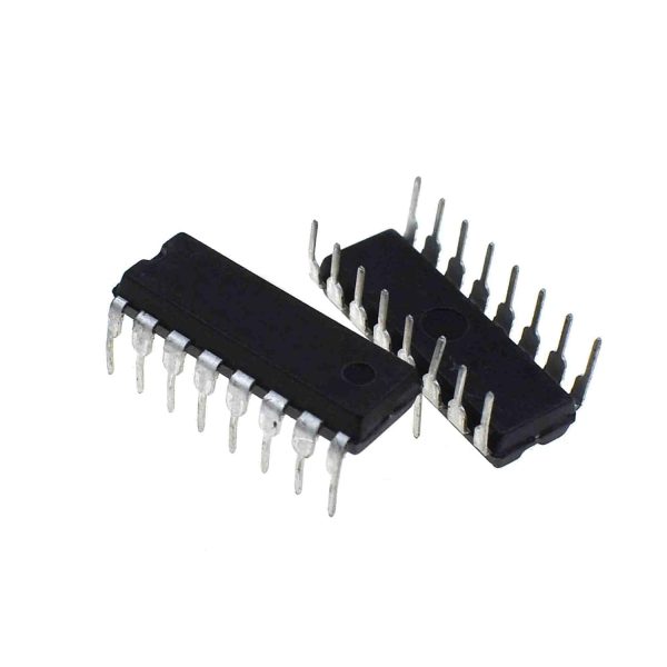
The 74LS132N TTL is a TTL integrated circuit containing four independent square wave oscillators. This component is essential for electronic and Arduino projects that require square wave signals or complex logic circuits.
Features
- 2 pieces of 74LS132N TTL
- TTL integrated circuit with four independent square wave oscillators
- Ideally suited for complex logic and filtering
What it is for
The 74LS132N TTL is used to create projects that require square wave signals, for example, for an LED display that changes the lighting sequence based on the square wave signal generated by the component. It is compatible with Arduino and can be used in various types of electronic circuits.
Tutorial: How to Use the 74LS132N TTL Integrated Circuit
The 74LS132N TTL is a TTL integrated circuit containing four independent square wave oscillators. This component is useful for makers creating projects that require square wave signals or for those working on logic circuits.
What you need
- Arduino Uno or compatible
- USB cable
- Breadboard
- Jumper wires
- LEDs
- Resistors
Steps
- Connect the Arduino to the computer via the USB cable.
- Connect the 74LS132N to the breadboard.
- Connect the VCC and GND pins of the 74LS132N to the voltage references on the breadboard.
- Connect the input and output pins of the 74LS132N to the digital pins of the Arduino.
- Write the Arduino sketch to test the 74LS132N.
- Verify that the LEDs connected to the output pins of the 74LS132N turn on and off alternately.
- Modify the sketch to change the frequency of the square wave oscillators.
- Test the 74LS132N with other combinations of inputs to verify its functionality.
Example code
void setup() {
  pinMode(2, OUTPUT);
  pinMode(3, OUTPUT);
}

void loop() {
  digitalWrite(2, HIGH);
  digitalWrite(3, LOW);
  delay(500);
  digitalWrite(2, LOW);
  digitalWrite(3, HIGH);
  delay(500);
}
Mini project
Create an LED display that changes the sequence of lighting based on the square wave signal generated by the 74LS132N. The project takes about 30 minutes.
Common mistakes
- Do not verify the correct power supply voltage for the 74LS132N.
- Do not correctly connect the input and output pins.
- Do not test the sketch with different input combinations.
- Do not check the datasheet for the technical specifications of the 74LS132N.
Recommended accessories
- Arduino Uno R3
- Breadboard 400 points
- USB A-MicroB cable
- Kit of various LEDs and resistors
Frequently asked questions
Which pins of the 74LS132N are used for power supply?
The VCC and GND pins.
What voltage is required to power the 74LS132N?
Check the datasheet.
Which pins of the 74LS132N are used for output?
Check the datasheet.

Reviews
There are no reviews yet.