 EN
 IT Italiano
 ES Español
 FR Français
 DE Deutsch
Description
Technical Description
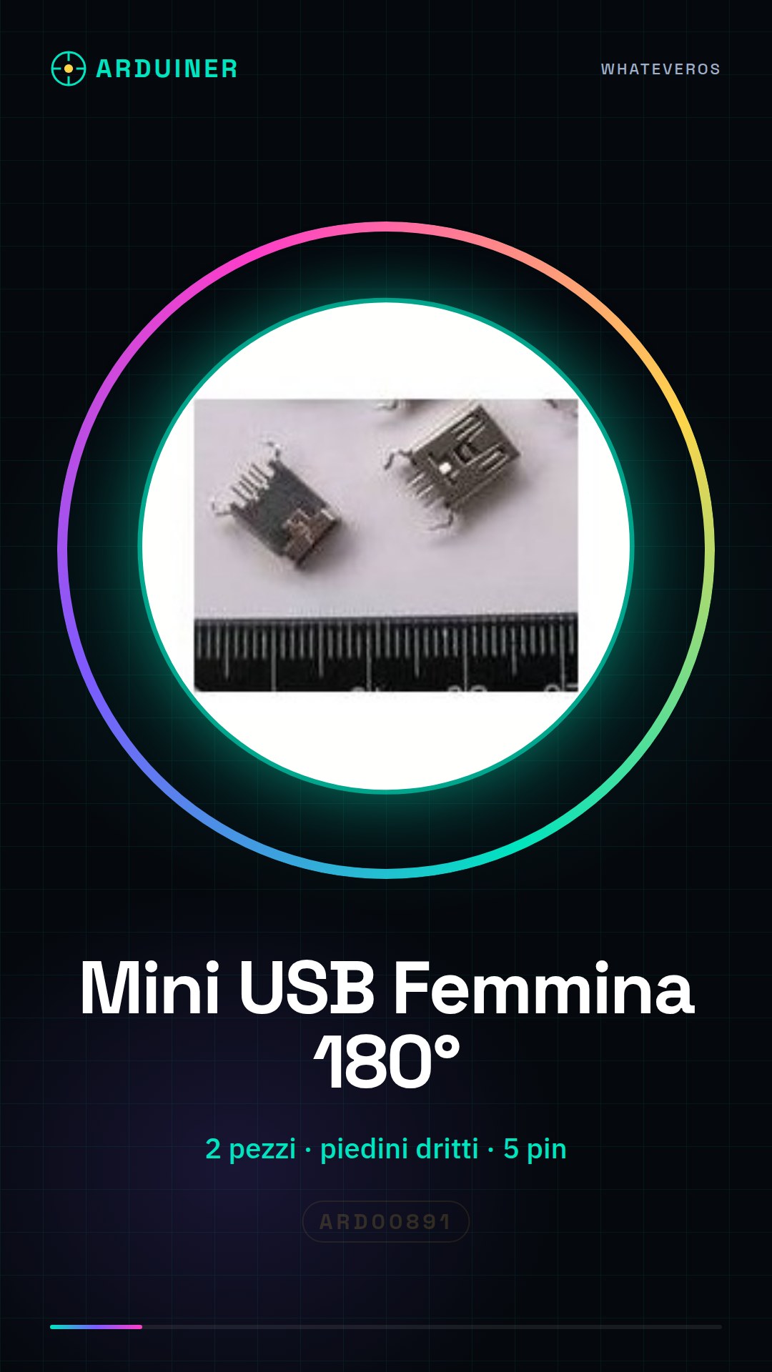
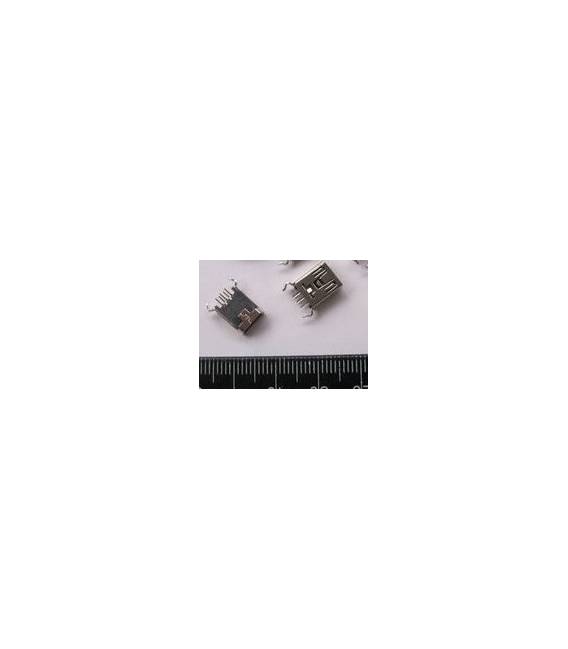
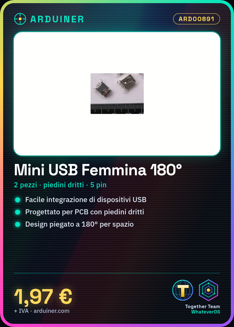
The Right-Angle Mini USB Female Connector is a component used for USB connectivity in electronic projects. This type of connector offers a bent mounting solution that allows saving space on the printed circuit board (PCB) and optimizing the component layout. The connector features straight leads that must be soldered to the PCB to ensure a stable and secure connection. It is important to align the leads with the PCB traces and solder them correctly to avoid short circuits.
The Right-Angle Mini USB Female Connector consists of five pins (5P) that connect to the USB device’s data and power signals. It is designed for use in applications requiring easy integration of USB port devices, such as Arduino boards or sensors.
During installation, it is important to ensure that the pins are properly aligned with the PCB traces and soldered correctly to avoid short circuits or unstable connections.
Key Specifications
| Parameter | Value |
| Model | Right-Angle Mini USB Female Connector 5P with straight pins |
| Quantity | 2 pieces |
| Number of pins | 5 |
| Bend angle | 180 degrees |
| Connector type | Female |
| Dimensions | N/D (see manufacturer’s datasheet) |
| Interface | USB Mini |
| Container | N/D (see the manufacturer’s technical sheet) |
Installation and Usage
- Prepare the printed circuit board (PCB) where you want to integrate the connector.
- Position the connector correctly on the PCB, ensuring that the leads are straight and well-aligned with the PCB traces.
- Solder each pin of the connector to the PCB delicately using a small amount of solder to ensure good contact.
- Check the soldering on each lead, ensuring there are no solder bridges or other imperfections.
- Connect the connector to a USB cable to test the electronic connection integrity.
Compatibility and Requirements
- The Right-Angle Mini USB Female Connector is compatible with Arduino boards and other devices that use the Mini USB interface.
- To use this connector, a printed circuit board (PCB) with corresponding traces and a USB cable are required.
- The connector can be used in electronic prototyping and home automation projects.
Limitations and Important Notes
- The connector is not designed for frequent physical connections or applications with continuous movement.
- It is important to verify that the pins are properly aligned and soldered before using the connector.
- The connector is not designed to withstand extreme temperature or humidity conditions.
- It is not recommended to use the connector in projects requiring high-speed USB connectivity.
Troubleshooting
The connector does not connect properly to the USB cable.
Possible cause: Insufficient or missing soldering.
Solution: Resolder the connector pins.
The connector easily disconnects from the PCB.
Possible cause: Pins not properly aligned with the PCB traces.
Solution: Re-work and re-solder the connector pins.
The electrical connection between the connector and the PCB is unstable.
Probable cause: Insufficient or missing solder joints.
Solution: Check and re-work the solder joints on each pin.
The connector does not work properly with the Arduino device.
Probable cause: Incorrect PCB configuration or USB cable connection.
Solution: Check the PCB configuration and USB cable connection.
Use cases
Home Temperature Sensor
Objective: Monitor the internal temperature of the home.
What’s needed: Right-Angle Mini USB Female Connector, temperature sensors, Arduino board.
Steps: 1) Install the connector on the PCB. 2) Solder the connector to the PCB. 3) Connect the temperature sensor. 4) Connect the sensor to the PCB. 5) Configure the Arduino code to read the sensor data.
Expected Result: The system monitors the internal temperature of the house and sends the data via USB.
Step Counter for Hobby
Objective: Count steps during physical activity.
What’s needed: Right-Angle Mini USB Female Connector, motion sensor, Arduino board.
Steps: 1) Install the connector on the PCB. 2) Solder the connector to the PCB. 3) Connect the motion sensor. 4) Connect the sensor to the PCB. 5) Configure the Arduino code to count steps.
Expected Result: The system counts steps during physical activity and sends the data via USB.
Remote Monitoring System for School
Objective: Monitor environmental data in a school laboratory.
What’s needed: Right-Angle Mini USB Female Connector, environmental sensors, Arduino board.
Steps: 1) Install the connector on the PCB. 2) Solder the connector to the PCB. 3) Connect environmental sensors. 4) Connect the sensors to the PCB. 5) Configure the Arduino code to read sensor data.
Expected result: The system monitors environmental data in a school laboratory and sends data via USB.
Home Light Control System
Objective: Control the light intensity in a room.
What’s needed: Right-Angle Mini USB Female Connector, light sensors, Arduino.
Steps: 1) Install the connector on the PCB. 2) Solder the connector to the PCB. 3) Connect the light sensors. 4) Connect the sensors to the PCB. 5) Configure the Arduino code to adjust the light intensity.
Expected result: The system adjusts the light intensity in a room and sends data via USB.
Highway Traffic Monitoring System
Objective: Monitor traffic on a highway.
What’s needed: Right-Angle Mini USB Female Connector, motion sensors, Arduino board.
Steps: 1) Install the connector on the PCB. 2) Solder the connector to the PCB. 3) Connect the motion sensors. 4) Connect the sensors to the PCB. 5) Configure the Arduino code to monitor traffic.
Expected result: The system monitors traffic on a highway and sends data via USB.
Energy consumption monitoring system for a company
Objective: Monitor energy consumption in a company.
What’s needed: Right-Angle Mini USB Female Connector, energy consumption sensors, Arduino board.
Steps: 1) Install the connector on the PCB. 2) Solder the connector to the PCB. 3) Connect the energy consumption sensors. 4) Connect the sensors to the PCB. 5) Configure the Arduino code to monitor energy consumption.
Expected Result: The system monitors the energy consumption of a company and sends the data via USB.
City Noise Monitoring System
Objective: To monitor the noise level in a city.
What’s needed: Right-Angle Mini USB Female Connector, noise sensors, Arduino board.
Steps: 1) Install the connector on the PCB. 2) Solder the connector to the PCB. 3) Connect the noise sensors. 4) Connect the sensors to the PCB. 5) Configure the Arduino code to monitor the noise.
Expected Result: The system monitors the noise level in a city and sends the data via USB.
City Air Quality Monitoring System
Objective: To monitor the air quality in a city.
What’s needed: Right-Angle Mini USB Female Connector, air quality sensors, Arduino board.
Steps: 1) Install the connector on the PCB. 2) Solder the connector to the PCB. 3) Connect the air quality sensors. 4) Connect the sensors to the PCB. 5) Configure the Arduino code to monitor air quality.
Expected result: The system monitors air quality in a city and sends data via USB.
In the package
- 2 pieces
Complete the project
- 6 Pieces Right-Angle Mini USB Female Connector 5P 90 degrees: This connector is compatible with other right-angle Mini USB female connectors bent at 90 degrees.
- 4 Pieces USB Type B Female Socket Connector 90 degrees bent: This connector is compatible with USB Type B female connectors bent at 90 degrees.
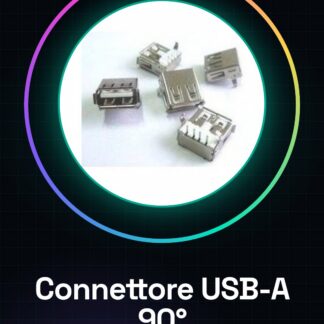
- 6 Pieces USB Type A Female Socket Connector 90 degrees bent: This connector is compatible with USB Type A female connectors bent at 90 degrees.
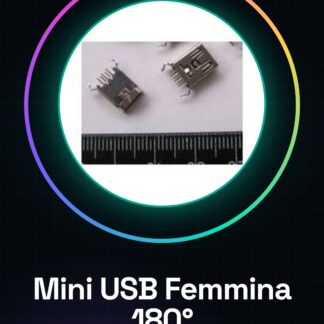
- 5 Pieces Mini USB Female Socket Connector 5P SMD
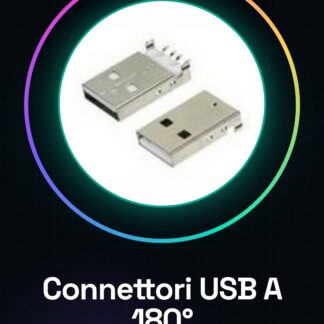
- 12 Pieces Right-Angle USB A Male Socket White
Technical FAQ
How can I verify the quality of the soldering?
Use a multimeter to test the electrical integrity of the connection between the connector and the PCB.
What is the difference between this 180-degree bent connector and the straight one?
The bent connector offers a more flexible design, allowing for space savings on the PCB.
What are the usage limitations of this connector?
The connector is not designed for frequent physical connections or applications with continuous movement.
What are the PCB configuration requirements for using this connector?
The PCB must have corresponding traces for the connector pins and a USB cable for connectivity.
Tutorial: How to use Mini USB Female Connector Bent
The Mini USB Female Connector bent at 180 degrees is an essential component for projects requiring easy integration of USB port devices. Ideal for beginner and intermediate makers, this connector allows for easy connection of devices such as Arduino or sensors.
What you need
- Arduino
- USB cable
- soldering tweezers
- solder
Steps
- Prepare the printed circuit board (PCB) where you want to integrate the connector.
- Position the connector correctly on the PCB, ensuring that the pins are straight and well-aligned with the PCB traces.
- Solder each pin of the connector to the PCB delicately using a small amount of solder to ensure good contact.
- Check the soldering on each pin, ensuring there are no solder bridges or other imperfections.
- Connect the connector to a USB cable to test the integrity of the electronic connection.
Mini project
Create a remote monitoring system with Arduino that sends data via USB.
Common mistakes
- Insufficient or non-existent soldering.
- Pins not properly aligned with the PCB traces.
- Physical USB cable connection unstable due to incorrect connector placement.
Recommended accessories
- USB cable
- Soldering kit
- Multimeter
Frequently asked questions
How can I check the quality of the soldering?
Use a multimeter to test the electrical integrity of the connection between the connector and the PCB.
What is the difference between this 180-degree bent connector and the straight one?
The bent connector offers a more flexible design, allowing for space savings on the PCB.
Reviews
There are no reviews yet.