 EN
 IT Italiano
 ES Español
 FR Français
 DE Deutsch
Description
Technical Specifications
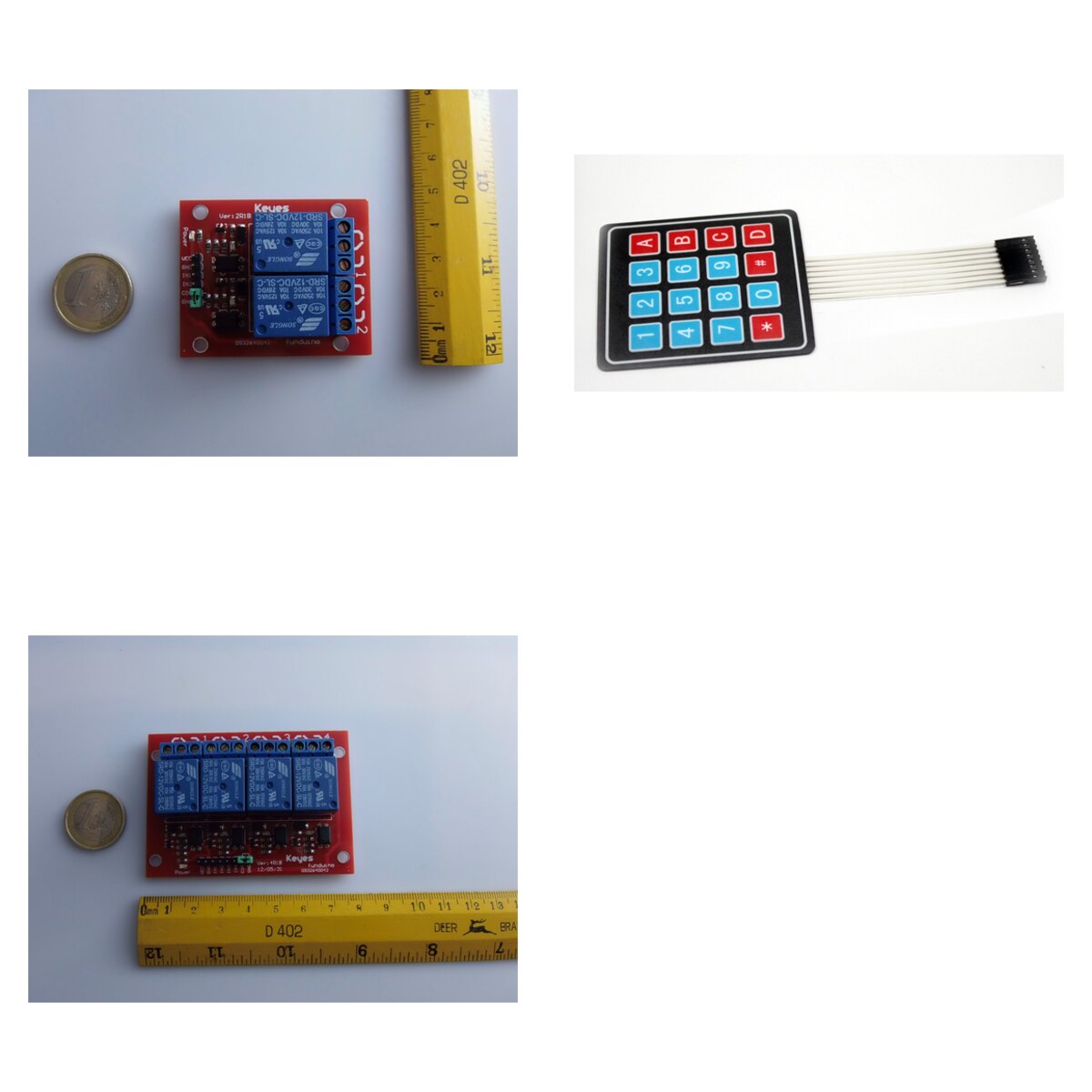
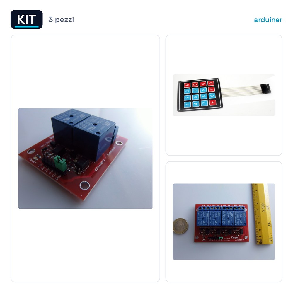
The 2 Channel 12V Relay Module for Arduino PIC ARM AVR D + 4×4 Matrix Keypad 16 Keys + 4 Channel 12V Relay Module is a set of components for electronic automation projects. It includes a 2-channel 12V relay module, a 4×4 matrix keypad with 16 keys, and a 4-channel 12V relay module. These components can be used to control electrical devices from a microcontroller like Arduino, allowing the management of electrical load activation and deactivation through digital signals.
The 2-channel and 4-channel relay modules provide an electrical isolation between the microcontroller and the loads, protecting the control circuit from unwanted or damaging loads. The 4×4 matrix keypad can be used for user input, allowing interaction with the system through physical keys.
This kit is suitable for projects that require the control of electrical devices and user interaction through buttons, such as home automation, security system prototypes, and laboratory projects.
Key Specifications
| Parameter | Value |
| Model | Kit 2 Channels 12V Relay Module for Arduino PIC ARM AVR D + 4×4 Matrix Keypad 16 Keys + 4 Channels 12V Relay Module for |
| Quantity | 1 |
| Operating Voltage | 12V |
| Interface | GPIO |
| Dimensions | N/D (see manufacturer’s datasheet) |
| Package | N/D (see manufacturer’s datasheet) |
Installation and Usage
- Connect the 2-channel and 4-channel relay modules to the GPIO pins of the Arduino microcontroller.
- Connect electrical loads to the relay module through the connectors.
- Connect the 4×4 matrix keypad to the GPIO pins of the Arduino microcontroller.
- Power the relay module and matrix keypad with a 12V power supply.
- Run a test program to verify the operation of the relays and matrix keypad.
Compatibility and Requirements
- The kit is compatible with Arduino, PIC, ARM, and DSP microcontrollers.
- A control software is required to manage GPIO signals and electrical loads.
- A 12V power adapter is needed to power the relay modules and matrix keypad.
Limitations and Important Notes
- The kit does not include the control software.
- The kit is not designed for electrical loads with voltages below 12V.
- It is important to check the compatibility of electrical loads with the relay module.
- The kit does not include specific connectors for electrical loads.
Troubleshooting
The relay does not activate.
Possible cause: Unstable connection between the microcontroller and the relay module.
Solution: Check and reinforce the connection between the microcontroller and the relay module.
The matrix keyboard does not register key presses.
Probable cause: Unstable connection between the matrix keyboard and the microcontroller.
Solution: Check and reinforce the connection between the matrix keyboard and the microcontroller.
The relay module overheats.
Probable cause: Too heavy electrical loads or overload.
Solution: Check the correct configuration of electrical loads and reduce power if necessary.
The relay module does not activate after the first key press.
Probable cause: Software issue or connection problem.
Solution: Check the software code and the connection between the microcontroller and the relay module.
Use cases
Home security system
Objective: Control the lights and locks of the house.
Needed: 2 Channel 12V Relay Module for Arduino PIC ARM AVR D + 4×4 Matrix Keypad 16 Keys + 4 Channel 12V Relay Module for
Steps: 1) Connect the lights and locks to the relays on the module. 2) Configure the microcontroller to manage GPIO signals. 3) Test the security system. 4) Verify the proper functioning of the matrix keypad for access.
Expected Result: The home security system is ready to be used.
Garage Automation
Objective: Control the opening and closing system of the garage.
Needed: 2 Channel 12V Relay Module for Arduino PIC ARM AVR D + 4×4 Matrix Keypad 16 Keys + 4 Channel 12V Relay Module for
Steps: 1) Connect the garage door opening and closing system to the relays on the module. 2) Configure the microcontroller to manage GPIO signals. 3) Test the garage automation system. 4) Verify the proper functioning of the matrix keypad for access.
Expected result: The garage automation system is ready to be used.
Temperature Control System
Objective: Regulate heating and cooling of an environment.
Required: 2 Channel 12V Relay Module for Arduino PIC ARM AVR D + 4×4 Matrix Keypad 16 Keys + 4 Channel 12V Relay Module for
Steps: 1) Connect the heating and cooling devices to the relays on the module. 2) Configure the microcontroller to manage GPIO signals. 3) Test the temperature control system. 4) Verify the proper functioning of the matrix keypad for access.
Expected result: The temperature control system is ready to be used.
External Lighting Control System
Objective: To regulate the external lighting of a building.
What’s needed: 2 Channel 12V Relay Module for Arduino PIC ARM AVR D + 4×4 Matrix Keypad 16 keys + 4 Channel 12V Relay Module for
Steps: 1) Connect the external lights to the relays on the module. 2) Configure the microcontroller to manage the GPIO signals. 3) Test the external lighting control system. 4) Verify the proper functioning of the matrix keypad for access.
Expected result: The external lighting control system is ready to be used.
Electronic Lock Control System
Objective: To regulate the electronic locks of a building.
What’s needed: 2 Channel 12V Relay Module for Arduino PIC ARM AVR D + 4×4 Matrix Keypad 16 keys + 4 Channel 12V Relay Module for
Steps: 1) Connect the electronic locks to the relays on the module. 2) Configure the microcontroller to manage GPIO signals. 3) Test the electronic lock control system. 4) Verify the proper functioning of the matrix keyboard for access.
Expected result: The electronic lock control system is ready to be used.
Fan Control System
Objective: Regulate the fans in an environment.
What’s needed: 2 Channel 12V Relay Module for Arduino PIC ARM AVR D + 4×4 Matrix Keyboard 16 Keys + 4 Channel 12V Relay Module for
Steps: 1) Connect the fans to the relays on the module. 2) Configure the microcontroller to manage GPIO signals. 3) Test the fan control system. 4) Verify the proper functioning of the matrix keyboard for access.
Expected Result: The fan control system is ready to be used.
Electronic Door Control System
Objective: To regulate the electronic doors of a building.
What’s needed: 2 Channel 12V Relay Module for Arduino PIC ARM AVR D + 4×4 Matrix Keypad 16 keys + 4 Channel 12V Relay Module for
Steps: 1) Connect the electronic doors to the relays on the module. 2) Configure the microcontroller to manage GPIO signals. 3) Test the electronic door control system. 4) Verify the proper functioning of the matrix keypad for access.
Expected Result: The electronic door control system is ready to be used.
Internal Lighting Control System
Objective: To regulate the internal lights of an environment.
What’s needed: 2 Channel 12V Relay Module for Arduino PIC ARM AVR D + 4×4 Matrix Keypad 16 keys + 4 Channel 12V Relay Module for
Steps: 1) Connect the internal lights to the relays on the module. 2) Configure the microcontroller to handle GPIO signals. 3) Test the internal light control system. 4) Verify the proper functioning of the 4×4 matrix keyboard for access.
Expected result: The internal light control system is ready to be used.
In the package
- Kit 2 Channels 12V Relay Module for Arduino PIC ARM AVR D + 4×4 Matrix Keypad 16 keys + 4 Channels 12V Relay Module for
Complete the project
- 4 Channels 5V Relay Module for Arduino PIC ARM AVR DSP: The 4-channel 5V relay module can be used as an alternative for projects with voltages below 12V.
- 3 Channels 3.3V 5V Relay Module with optocoupler for PIC AVR DSP ARM: The 3-channel 3.3V 5V relay module with optocoupler can be used as an alternative for projects with voltages below 12V.
- 4×4 Matrix Keypad 16 keys for Arduino: The 4×4 matrix keyboard with 16 keys can be used as an alternative for projects requiring a key-based user interface.
- 12V 16 Channel Relay Module with Optocoupler Isolated Optoisolation Protection and LM2576 Chip: The 12V 16 channel relay module with optocoupler can be used as an alternative for projects requiring a larger number of relay channels.
Technical FAQs
Does the kit include the control software?
No, the kit does not include the control software. It is necessary to develop or install a separate control software.
What are the power limits of the relay module?
The power limits of the relay module are not specified in the product data. It is recommended to check the manufacturer’s documentation or contact technical support.
What are the temperature limits of the relay module?
The temperature limits of the relay module are not specified in the product data. It is recommended to check the manufacturer’s documentation or contact technical support.
What are the voltage limits of the relay module?
The relay module is designed to operate at 12V. It is recommended not to use voltages lower than 12V or higher than 12V without verifying compatibility with the module.
Reviews
There are no reviews yet.